EP0935334A2 - Electronic device fitted with power generators - Google Patents
Electronic device fitted with power generators Download PDFInfo
- Publication number
- EP0935334A2 EP0935334A2 EP99300821A EP99300821A EP0935334A2 EP 0935334 A2 EP0935334 A2 EP 0935334A2 EP 99300821 A EP99300821 A EP 99300821A EP 99300821 A EP99300821 A EP 99300821A EP 0935334 A2 EP0935334 A2 EP 0935334A2
- Authority
- EP
- European Patent Office
- Prior art keywords
- generator
- electronic device
- thermoelectric generator
- storage means
- solar generator
- Prior art date
- Legal status (The legal status is an assumption and is not a legal conclusion. Google has not performed a legal analysis and makes no representation as to the accuracy of the status listed.)
- Granted
Links
- 230000005611 electricity Effects 0.000 abstract description 15
- 230000036760 body temperature Effects 0.000 description 9
- 230000007423 decrease Effects 0.000 description 6
- 238000010248 power generation Methods 0.000 description 6
- 239000003990 capacitor Substances 0.000 description 5
- 239000004065 semiconductor Substances 0.000 description 5
- 238000010586 diagram Methods 0.000 description 3
- 238000004146 energy storage Methods 0.000 description 2
- 239000011521 glass Substances 0.000 description 2
- 238000000034 method Methods 0.000 description 2
- 229920003023 plastic Polymers 0.000 description 2
- WHXSMMKQMYFTQS-UHFFFAOYSA-N Lithium Chemical compound [Li] WHXSMMKQMYFTQS-UHFFFAOYSA-N 0.000 description 1
- HBBGRARXTFLTSG-UHFFFAOYSA-N Lithium ion Chemical compound [Li+] HBBGRARXTFLTSG-UHFFFAOYSA-N 0.000 description 1
- 230000005678 Seebeck effect Effects 0.000 description 1
- 239000000956 alloy Substances 0.000 description 1
- 229910045601 alloy Inorganic materials 0.000 description 1
- 229910021417 amorphous silicon Inorganic materials 0.000 description 1
- 229910052797 bismuth Inorganic materials 0.000 description 1
- JCXGWMGPZLAOME-UHFFFAOYSA-N bismuth atom Chemical compound [Bi] JCXGWMGPZLAOME-UHFFFAOYSA-N 0.000 description 1
- 238000010276 construction Methods 0.000 description 1
- 230000003247 decreasing effect Effects 0.000 description 1
- 230000000694 effects Effects 0.000 description 1
- 239000011810 insulating material Substances 0.000 description 1
- 229910052744 lithium Inorganic materials 0.000 description 1
- 229910001416 lithium ion Inorganic materials 0.000 description 1
- 230000002093 peripheral effect Effects 0.000 description 1
- 239000004033 plastic Substances 0.000 description 1
- 239000010453 quartz Substances 0.000 description 1
- 229910052594 sapphire Inorganic materials 0.000 description 1
- 239000010980 sapphire Substances 0.000 description 1
- VYPSYNLAJGMNEJ-UHFFFAOYSA-N silicon dioxide Inorganic materials O=[Si]=O VYPSYNLAJGMNEJ-UHFFFAOYSA-N 0.000 description 1
- 229910052714 tellurium Inorganic materials 0.000 description 1
- PORWMNRCUJJQNO-UHFFFAOYSA-N tellurium atom Chemical compound [Te] PORWMNRCUJJQNO-UHFFFAOYSA-N 0.000 description 1
- 239000012780 transparent material Substances 0.000 description 1
Images


Classifications
-
- H—ELECTRICITY
- H10—SEMICONDUCTOR DEVICES; ELECTRIC SOLID-STATE DEVICES NOT OTHERWISE PROVIDED FOR
- H10N—ELECTRIC SOLID-STATE DEVICES NOT OTHERWISE PROVIDED FOR
- H10N10/00—Thermoelectric devices comprising a junction of dissimilar materials, i.e. devices exhibiting Seebeck or Peltier effects
-
- G—PHYSICS
- G04—HOROLOGY
- G04C—ELECTROMECHANICAL CLOCKS OR WATCHES
- G04C10/00—Arrangements of electric power supplies in time pieces
-
- H—ELECTRICITY
- H02—GENERATION; CONVERSION OR DISTRIBUTION OF ELECTRIC POWER
- H02S—GENERATION OF ELECTRIC POWER BY CONVERSION OF INFRARED RADIATION, VISIBLE LIGHT OR ULTRAVIOLET LIGHT, e.g. USING PHOTOVOLTAIC [PV] MODULES
- H02S10/00—PV power plants; Combinations of PV energy systems with other systems for the generation of electric power
- H02S10/10—PV power plants; Combinations of PV energy systems with other systems for the generation of electric power including a supplementary source of electric power, e.g. hybrid diesel-PV energy systems
-
- Y—GENERAL TAGGING OF NEW TECHNOLOGICAL DEVELOPMENTS; GENERAL TAGGING OF CROSS-SECTIONAL TECHNOLOGIES SPANNING OVER SEVERAL SECTIONS OF THE IPC; TECHNICAL SUBJECTS COVERED BY FORMER USPC CROSS-REFERENCE ART COLLECTIONS [XRACs] AND DIGESTS
- Y02—TECHNOLOGIES OR APPLICATIONS FOR MITIGATION OR ADAPTATION AGAINST CLIMATE CHANGE
- Y02B—CLIMATE CHANGE MITIGATION TECHNOLOGIES RELATED TO BUILDINGS, e.g. HOUSING, HOUSE APPLIANCES OR RELATED END-USER APPLICATIONS
- Y02B10/00—Integration of renewable energy sources in buildings
- Y02B10/70—Hybrid systems, e.g. uninterruptible or back-up power supplies integrating renewable energies
-
- Y—GENERAL TAGGING OF NEW TECHNOLOGICAL DEVELOPMENTS; GENERAL TAGGING OF CROSS-SECTIONAL TECHNOLOGIES SPANNING OVER SEVERAL SECTIONS OF THE IPC; TECHNICAL SUBJECTS COVERED BY FORMER USPC CROSS-REFERENCE ART COLLECTIONS [XRACs] AND DIGESTS
- Y02—TECHNOLOGIES OR APPLICATIONS FOR MITIGATION OR ADAPTATION AGAINST CLIMATE CHANGE
- Y02E—REDUCTION OF GREENHOUSE GAS [GHG] EMISSIONS, RELATED TO ENERGY GENERATION, TRANSMISSION OR DISTRIBUTION
- Y02E10/00—Energy generation through renewable energy sources
- Y02E10/50—Photovoltaic [PV] energy
Abstract
Description
- The present invention relates to various kinds of electronic devices and appliances such as electronic wristwatches, portable communications devices, and domestic electrical appliances and, more particularly, to electronic devices fitted with power generators.
- Heretofore, electronic devices fitted with power generators have been developed as electronic devices such as electronic wristwatches and the like. Various types are available as power generators. Especially, thermoelectric generators can be made compact and so they are being developed so as to be applied to various electronic devices and appliances.
- An electronic wristwatch fitted with a thermolectric generator is worn on an arm such that suction of heat by the thermoelectric generator is conducted from the arm. Heat is dissipated to the outside air. In this way, electric power is generated by making use of a temperature difference. Accordingly, when the electronic wristwatch is detached from the arm, no temperature difference is produced and so power generation may be stopped. If power generation is stopped for a long time, electric power stored in a storage device might be exhausted. Furthermore, when the outside air temperature and the body temperature on the arm become equal, power generation comes to a stop. In this case, there is the possibility that the electric power stored in the storage device is used up.
- Since a thermoelectric generator produces only a small amount of electric power, if the storage device is exhausted, it is difficult to store a sufficient amount of electric power in the storage device in a short time after attaching the watch to an arm. For example, where a thermoelectric device has a temperature difference of about 2°C, the electric power that can be generated is about 13.3 µW, provided that the generated voltage is 0.4 V, the internal resistance is about 1500 Ω, and the input impedance of a voltage step-up means for stepping up the generated voltage is 1500 Ω and that the loss of voltage step-up means is neglected. The electric power consumed by the electronic wristwatch is approximately 1 to 2 µW. Where a lithium-ion secondary battery having a diameter of 6 mm is used as a power storage device, energy of about 6.5 J can be stored. Accordingly, if the device is worn on an arm and should be fully charged, it takes a time of 135.8 hours even if consumption and loss in the load circuit are neglected.
- Accordingly, if power generation of the thermoelectric generator is stopped for a long time as encountered when the electronic wristwatch is detached from the arm, the electric power storage device is exhausted. This brings the timepiece to a stop.
- One proposed method for solving this problem is to reduce the frequency at which the second hand of a watch or clock is driven if the storage voltage drops, thus lowering the electric power consumed (see Japanese Patent Unexamined Publication No. 287080/1995). With this method, the electric power consumed can be decreased but cannot be reduced down to zero. Therefore, if power generation of the thermoelectric generator stops for a long time, there arises the problem that the storage device is exhausted.
- If a thermoelectric generator is used in various electronic devices and appliances other than electronic wristwatches such as portable communications devices and domestic electric appliances, the same problem arises if no temperature difference occurs.
- The present invention is intended to suppress decreases in the electric power stored in an electric storage device of an electronic device having a thermoelectric generator.
- An electronic device fitted with power generators in accordance with the present invention is characterized by comprising: a thermoelectric generator; a solar generator; a switching means for delivering at least one of electric power generated by said thermoelectric generator and electric power generated by said solar generator; an electric energy storage means charged by output from said switching means; and an electronic device body circuit powered by said electric energy storage means. If there is a temperature difference, the thermoelectric generator generates electricity. The solar generator receives light such as sunlight and generates electricity. At least one of the electric power generated by the thermoelectric generator and the electric power generated by the solar generator is supplied to the storage means via the switching means, thus charging the storage means. The electronic device body circuit is powered by the storage means.
- Accordingly, in regions where large temperature differences are obtained but the sunlight is weak and the hours of sunlight are short as in cold regions, the device can be chiefly charged by the thermoelectric generator. On the other hand, in areas where large temperature differences cannot be derived but the sunlight is strong and the hours of sunlight are long as in the vicinities of equatorial districts, the device can be mainly charged by the solar generator. Therefore, the drawbacks of the power generators can be compensated by using the thermoelectric generator and the solar generator in combination. The storage device can be charged without being affected greatly by regional environments. Decreases in the electric power stored in the storage means can be suppressed.
- The voltage generated by the thermoelectric generator described above is relatively low and rises mildly. On the other hand, the voltage generated by the solar generator is relatively high and rises steeply. Therefore, it is desired to use the solar generator to power the voltage step-up means that steps up the voltage generated by the thermoelectric generator.
- Since the voltage generated by the thermoelectric generator is comparatively low, if the voltage of the thermoelectric generator is insufficient to start the voltage step-up means, the solar cell generator is made of one stage of cell and used as a power supply for starting the voltage step-up means. After starting the voltage step-up means, the voltage generated by the thermoelectric generator is stepped up and used to power the voltage step-up means. In this way, the solar generator is used.
- The aforementioned electronic device body circuit can comprise an electronic timepiece circuit and a display means driven by the electronic timepiece circuit to provide a display of time.
- The solar generator is disposed on the time display face of the display means. In normal use, the solar generator can be made to produce electricity and thus the device is charged.
- The solar generator is disposed on the opposite side of the time display face of the display means so as to be capable of receiving light via a transparent rear cover. Hence, the appearance of the electronic device can be aesthetically improved.
- A preferred form of the present invention is illustrated in the accompanying drawings in which:
- Fig. 1 is a block diagram of an electronic wristwatch fitted with power generators in accordance with the present invention;
- Fig. 2 is a side elevation showing the structure of the thermoelectric generator of Fig. 1;
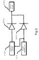
- Fig. 3 is a view showing details of a circuit forming the switching means of Fig. 1;
- Fig. 4 is a plan view showing the structure of an electronic wristwatch fitted with power generators in accordance with the invention;
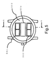
- Fig. 5 is a bottom view showing the structure of another embodiment of an electronic wristwatch fitted with power generators in accordance with the invention; and
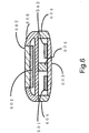
- Fig. 6 is a cross-sectional view of the electonic wristwatch fitted with power generators and shown in Fig. 5, taken on A-A.
-
- Fig. 1 is a block diagram showing an embodiment of the present invention, depicting an example of an electronic wristwatch fitted with power generators. In Fig. 1, a thermoelectric generator 101 has an output portion connected with a first input portion of a switching means 104 via a step-up means 102. A
solar generator 103 has an output portion connected with a second input portion of the switching means 104 and with the power-supply terminals of the voltage step-up means 102. The output portion of the switching means 104 is connected with an electrical storage means 105. The output portion of the storage means 105 is so connected as to act as a power supply for anelectronic timepiece circuit 106 and a display means 107. Theelectronic timepiece circuit 106 and the display means 107 form an electronic device body circuit. The power-supply terminals of the voltage step-up means 102 are connected also with the storage means 105 such that it can also be fed from the storage means 105 in a manner not shown. - The details of the construction of the thermoelectric generator 101 will be described later. Since it is difficult to directly drive the
electronic timepiece circuit 106 and the display means 107 by the voltage generated by the thermoelectric generator, the voltage generated by the thermoelectric generator 101 is stepped up by the voltage step-up means 102 to a voltage sufficient to drive theelectronic timepiece circuit 106 and the display means 107, thus electrically charging the storage means 105. One suitable example of the voltage step-up means 102 is a switched capacitor configuration consisting of a plurality of capacitors connected in parallel. These capacitors are charged in this condition. These capacitors are switched to a series connection by a switching device to produce a stepped up voltage. In this way, the operation for generating a stepped up voltage is repeated. In another suitable example, the current flowing through a coil is turned on and off by a switching device. The voltage is stepped up by making use of a self-induction current induced in the coil. This is adapted for miniaturization. The storage means 105 can be a lithium secondary battery, electric double-layer capacitors, or the like. - The
electronic timepiece circuit 106 uses a quartz oscillator circuit to generate 32,768 Hz. This is divided down to 1 second by a frequency divider circuit to drive a stepping motor every second. This rotates the second hand, the minute hand, and the hour hand forming the display means 107, thus displaying time. - The operation of the embodiment constructed in this way is described below.
- When one wears the electronic wristwatch on its arm, the thermoelectric generator 101 produces electricity utilizing a temperature difference between the body temperature on the arm and the outside temperature. The voltage generated by the thermoelectric generator 101 is stepped up by the voltage step-up means 102, and then supplied into the storage means 105 via the switching means 104 to charge the storage means 105.
- On the other hand, the
solar generator 103 receives light such as sunlight and generates electricity. The generated electric power is supplied to the storage means 105 via the switching means 103 to charge the storage means 105. - Where the thermoelectric generator 101 and the
solar generator 103 simultaneously generate electricity, the storage means 105 is charged from both generators via the switching means 104. - The
solar generator 103 produces a large amount of electric power. Furthermore, the voltage generated rises steeply. The solar generator has these characteristics. Where thesolar generator 103 consists of four stages of amorphous silicon solar cells connected in series having a size measuring 1 cm in height and 2.5 cm in width, the generator produces electric power of about 6 µW at 200 lux. Since the brightness of the outdoors on a cloudy day are about 10,000 lux, the amount of power generated is about 300 µW, which is about 22 times as high as the amount of electric power thermally generated, though this may vary depending on the area and the efficiency of the cells. - Accordingly, the voltage step-up means 102 can be driven, if the storage voltage of the storage means 105 is so lower that the voltage step-up means 102 cannot be driven, by starting the voltage step-up means 102 using the output from the
solar generator 103 as a power supply. The output from the thermoelectric generator 101 can stepped up to a required voltage and the storage means 105 can be charged. After the voltage step-up means 102 starts to operate and the storage means 105 becomes charged, the voltage step-up means 102 can be operated by the storage means 105. Therefore, if the power generation of thesolar generator 103 is stopped, the voltage step-up means 102 stably operates. - If the storage means 105 is charged, the
electronic timepiece circuit 106 and the display means 107 are powered by the storage means and time is displayed. - Fig. 2 is a side elevation showing the structure of the thermoelectric generator 101. This shows an example of thermoelement utilizing the Seebeck effect. In Fig. 2, electrodes 205-209, N-type semiconductor thermoelements 201, 203, and P-
type semiconductor thermoelements electrodes 206 and 208 are firmly mounted to an insulatingboard 210. Theelectrodes electrodes 205 and 209 are connected withoutput terminals 212. In the thermoelectric generator constructed as described above, if the insulatingboard 210 is made cooler and the insulating board 211 is made hotter, electric power is developed across theoutput terminals 212 with polarities as shown. Where this thermoelectric generator is used in an electronic wristwatch, if this wristwatch is worn on an arm, the body temperature on the arm is transmitted to the insulating board 211. The insulatingboard 210 is at the outside temperature. Electric power is generated owing to a temperature difference between the body temperature described above and the outside temperature. - In the example shown in Fig. 2, two pairs of P-type and N-type semiconductor thermoelements are used. A higher voltage can be produced by connecting tens of pairs of thermoelements, hundreds of pairs of thermoelements, or thousands of pairs of thermoelements in series. Where each semiconductor thermoelement is made of an alloy containing bismuth and tellurium, each pair of PN semiconductor thermoelements can generate a voltage of 200 µV at a temperature difference of 1°C.
- Fig. 3 is a circuit diagram showing the details of the switching means 104, which comprises
diodes diode 304 acts to prevent reverse current to the voltage step-up means 102. Thediode 305 serves to prevent reverse current to thesolar generator 103. - The step-up means 102 steps up the voltage generated by the thermoelectric generator 101 and charges the storage means 105 via the
diode 304. Thesolar generator 103 receives light, generates electricity, and charges the storage means 105 via thediode 305. - Where the thermoelectric generator 101 and the
solar generator 103 simultaneously generate electricity, the generated electricity is supplied to the storage means 105 via thediodes - Besides the switching means 104 described above, electronic switches such as MOS transistors can be used as the switching means 104. It may also be a mechanical switch operated externally.
- Fig. 4 is a plan view showing the structure of one embodiment of the present invention, depicting an example of electronic wristwatch fitted with power generators. In Fig. 4, a first
solar generator 401 and a secondsolar generator 402 are disposed on the dial 403 forming a time display face. These generators are electrically connected in series. Since each of thesolar generators - Fig. 5 is a bottom view showing the structure of another embodiment of the electronic wristwatch fitted with power generators, depicting an example of electronic wristwatch fitted with power generators. Fig. 6 is a cross section taken on A-A of Fig. 5.
- In Figs. 5 and 6, a
timepiece movement 601 including a movement, electrical storage means, an electronic timepiece circuit, a stepping motor, and hands is disposed in the center of the top of a heat-dissipating barrel 606 of an electronic wristwatch. The top is covered by a windshield glass 602. Athermoelectric generator 504 is disposed in the center of the lower portion of the electronic wristwatch. One end portion of thethermoelectric generator 504 is in contact with the heat-dissipating barrel 606, while the other end portion is in contact with a transparentrear cover 503.Solar generators solar generators thermoelectric generator 504 are covered by therear cover 503. - The peripheral portion of the lower portion of the electronic wristwatch is made of a heat-insulating member such as plastics and is formed by a heat-insulating
material 604 that blocks heat transfer on the side of therear cover 503 and on the side of the heat-dissipating barrel 606. Thus, the two opposite end portions of thethermoelectric generator 504 are thermally isolated from each other. Therear cover 503 is made of a transparent material such as sapphire, glass, or transparent plastic to permit light to hit thesolar generators - Where the electronic wristwatch constructed as described thus far is worn on an arm, the body temperature on the arm is transmitted to the other end portion of the
thermoelectric generator 504 via therear cover 503. Meanwhile, one end portion is held at the outside temperature by the heat-dissipating barrel 606. Thethermoelectric generator 504 produces electricity owing to a temperature difference between the body temperature and the outside temperature. - When the electronic wristwatch is detached from the arm and placed in such a way that the
rear cover 503 faces upward, sunlight or other light impinges on thesolar generators rear cover 503, whereby the generators produce electricity. Since the solar generators are disposed on the side of therear cover 503, the watch can be designed as an apparently normal watch. This is aesthetically advantageous. - As described thus far, in the embodiment of the invention, the thermoelectric generator 101 and the
solar generator 103 are used in conjunction. If no temperature difference is produced across the thermoelectric generator 101, electric power generated by thesolar generator 103 charges the storage means 105. Quick charging is also possible. In the dark as encountered when there exists no sunlight, it is possible to generate electricity using the thermoelectric generator 101. - Accordingly, in regions where large temperature differences are obtained between the body temperature and the outside temperature but the sunlight is weak and the hours of sunlight are short as in cold regions, the device can be chiefly charged by the thermoelectric generator 101. On the other hand, in areas where small temperature differences are produced between the body temperature and the outside temperature but the sunlight is strong and the hours of sunlight are long as in the vicinities of equatorial districts, the device can be mainly charged by the
solar generator 103. - The storage means 105 can be charged without being affected by the regional environments and so on by correcting the drawbacks of the generators, which is realized by using the thermoelectric generator 101 and the
solar generator 103 in combination. Therefore, the effect that decreases in the electric power stored in the storage means 105 can be suppressed is obtained. - Since the voltage generated by the thermoelectric generator 101 is relatively low, it is necessary to step up the voltage by the voltage step-up means 102. The voltage generated by the
solar generator 103 is relatively high and rises steeply. Thesolar generator 103 is used as a power supply for driving the step-up means 102. Therefore, if the electric power stored in the storage means 105 is fully consumed, it is possible to charge it by the electric power generated by the thermoelectric generator 101. Since the voltage generated by the thermoelectric generator 101 is relatively low, if the electric power stored in the storage means 105 is fully consumed, there is the possibility that the voltage step-up means 102 cannot be started. In this case, thesolar generator 103 is made of one stage of cell and used as a power supply for starting the voltage step-up means 102. So that the voltage step-up means 102 is operated. By starting step-up of the voltage generated by the thermoelectric generator 101, the storage means 105 is charged. Furthermore, it can act as a power supply for the voltage step-up means 102. - The thermoelectric generator and the solar generator are used as electric power generators and so decreases in size and weight can be accomplished. Electric power can be generated in normal use, i.e., when the device is worn on an arm. Consequently, the serviceability is quite high in use.
- The
solar generator 103 can generate electric power under normal use conditions by disposing thesolar generator 103 on the time display face of the timepiece. - Furthermore, the device can be aesthetically improved by placing the
solar generator 103 on the opposite side of the time display face described above so as to be capable of receiving light via the transparentrear cover 503. - In the present embodiment, electronic wristwatches have been described. The invention can also be applied to portable communications devices, domestic electrical appliances, and so on.
- In the present invention, an electrical storage means is electrically charged via a switching means by using at least one of electric power generated by a thermoelectric generator and electric power generated by a solar generator. Decreases in the electric power stored in the storage means can be suppressed.
- The aforementioned solar generator is used as a power supply for driving a step-up means. Therefore, if the electric power stored in the storage means is exhausted, the storage means can be charged by electric power generated by the thermoelectric generator.
- Since both a thermoelectric generator and a solar generator are used as electric power generators, decreases in size and weight can be realized. Where the invention is applied to an electronic wristwatch, electric power can be generated in normal use, i.e., when the watch is worn on an arm. Hence, the serviceability is quite high in use.
- Moreover, electric power can be generated in normal use by placing the solar generator on the time display face. In addition, the device can be aesthetically improved by placing the solar generator on the opposite side of the time display face.
Claims (6)
- An electronic device fitted with power generators, characterized by comprising:a thermoelectric generator;a solar generator;a switching means for delivering at least one of electric power generated by said thermoelectric generator and electric power generated by said solar generator;an electrical storage means charged by output from said switching means; andan electronic device body circuit powered by said electrical storage means.
- An electronic device fitted with power generators as set forth in claim 1, characterized in that there is further provided a voltage step-up means for stepping up voltage generated by said thermoelectric generator, and said voltage step-up means is driven by output from said solar generator.
- An electronic device fitted with power generators as set forth in claim 1 or 2, characterized in that said electronic device body circuit has an electronic timepiece circuit and a display means operated by said electronic timepiece circuit and provided a display of time.
- An electronic device fitted with power generators as set forth in claim 3, characterized in that said solar generator is disposed on a face of the time display provided in said display means.
- An electronic device fitted with power generators as set forth in claim 3, characterized in that said solar generator is disposed on the opposite side of said time display face of said display means so as to be capable of receiving light via a transparent rear cover.
- An electronic device fitted with power generators as set forth in claim 3, characterized in that said solar generator consists of one stage of photoelectric cell.
Applications Claiming Priority (3)
| Application Number | Priority Date | Filing Date | Title |
|---|---|---|---|
| JP2479998A JP3084521B2 (en) | 1998-02-05 | 1998-02-05 | Electronic equipment with generator |
| JP2479998 | 1998-02-05 | ||
| US09/237,232 US6320280B1 (en) | 1998-02-05 | 1999-01-26 | Electronic device fitted with power generators |
Publications (3)
| Publication Number | Publication Date |
|---|---|
| EP0935334A2 true EP0935334A2 (en) | 1999-08-11 |
| EP0935334A3 EP0935334A3 (en) | 2000-12-27 |
| EP0935334B1 EP0935334B1 (en) | 2004-09-01 |
Family
ID=26362377
Family Applications (1)
| Application Number | Title | Priority Date | Filing Date |
|---|---|---|---|
| EP19990300821 Expired - Lifetime EP0935334B1 (en) | 1998-02-05 | 1999-02-04 | Electronic device fitted with power generators |
Country Status (3)
| Country | Link |
|---|---|
| US (1) | US6320280B1 (en) |
| EP (1) | EP0935334B1 (en) |
| JP (1) | JP3084521B2 (en) |
Cited By (19)
| Publication number | Priority date | Publication date | Assignee | Title |
|---|---|---|---|---|
| WO2002045234A2 (en) * | 2000-11-28 | 2002-06-06 | Fujitsu Siemens Computers Gmbh | Electric power supply for a portable electronic device |
| GB2395027A (en) * | 2002-09-19 | 2004-05-12 | Charles Keith Maisels | Thermoelectric generator using body heat |
| EP1860708A2 (en) * | 2006-05-23 | 2007-11-28 | EnOcean GmbH | Thermoelectric generator |
| FR2901916A1 (en) * | 2006-05-30 | 2007-12-07 | Philibert Mazille | Hot junction and cold junction thermocouples e.g. iron-constantan thermocouple, connecting device for producing continuous electric current, has thermocouples arranged in series by capacitors, and constituted of plates and conductors |
| WO2009045660A1 (en) * | 2007-10-01 | 2009-04-09 | The Boeing Company | Energy harvesting system and method using multiple energy sources |
| EP2099079A1 (en) * | 2008-03-05 | 2009-09-09 | Stichting IMEC Nederland | Hybrid energy scavenger comprising thermopile unit and photovoltaic cells |
| WO2012061763A2 (en) * | 2010-11-05 | 2012-05-10 | Bsst Llc | Energy management systems and methods with thermoelectric generators |
| EP3021369A1 (en) * | 2014-11-14 | 2016-05-18 | J Touch Corporation | Thermoelectric power generator |
| US10141492B2 (en) | 2015-05-14 | 2018-11-27 | Nimbus Materials Inc. | Energy harvesting for wearable technology through a thin flexible thermoelectric device |
| US10290794B2 (en) | 2016-12-05 | 2019-05-14 | Sridhar Kasichainula | Pin coupling based thermoelectric device |
| WO2019116039A1 (en) * | 2017-12-13 | 2019-06-20 | Sandeep Kumar Chintala | Thermoelectric power generation |
| US10367131B2 (en) | 2013-12-06 | 2019-07-30 | Sridhar Kasichainula | Extended area of sputter deposited n-type and p-type thermoelectric legs in a flexible thin-film based thermoelectric device |
| CN110673460A (en) * | 2018-07-02 | 2020-01-10 | 斯沃奇集团研究和开发有限公司 | User testable thermoelectric watch |
| US10553773B2 (en) | 2013-12-06 | 2020-02-04 | Sridhar Kasichainula | Flexible encapsulation of a flexible thin-film based thermoelectric device with sputter deposited layer of N-type and P-type thermoelectric legs |
| US10566515B2 (en) | 2013-12-06 | 2020-02-18 | Sridhar Kasichainula | Extended area of sputter deposited N-type and P-type thermoelectric legs in a flexible thin-film based thermoelectric device |
| US20210088980A1 (en) * | 2018-07-02 | 2021-03-25 | The Swatch Group Research And Development Ltd | Thermoelectric watch testable in production or after-sales service |
| US11024789B2 (en) | 2013-12-06 | 2021-06-01 | Sridhar Kasichainula | Flexible encapsulation of a flexible thin-film based thermoelectric device with sputter deposited layer of N-type and P-type thermoelectric legs |
| US11276810B2 (en) | 2015-05-14 | 2022-03-15 | Nimbus Materials Inc. | Method of producing a flexible thermoelectric device to harvest energy for wearable applications |
| US11283000B2 (en) | 2015-05-14 | 2022-03-22 | Nimbus Materials Inc. | Method of producing a flexible thermoelectric device to harvest energy for wearable applications |
Families Citing this family (35)
| Publication number | Priority date | Publication date | Assignee | Title |
|---|---|---|---|---|
| EP1126336B1 (en) * | 1998-10-22 | 2008-12-31 | Citizen Holdings Co., Ltd. | Electronic timepiece |
| JP3747700B2 (en) | 1999-08-06 | 2006-02-22 | 日産自動車株式会社 | Intake air amount calculation device for variable valve engine |
| SG93287A1 (en) * | 1999-12-15 | 2002-12-17 | Ebauchesfabrik Eta Ag | Means for recharging a watch accumulator |
| JP2004129314A (en) * | 2000-03-17 | 2004-04-22 | Soichi Sato | Cogeneration system equipped with capacitor device |
| US7942010B2 (en) | 2001-02-09 | 2011-05-17 | Bsst, Llc | Thermoelectric power generating systems utilizing segmented thermoelectric elements |
| US7340304B2 (en) * | 2002-03-15 | 2008-03-04 | Biomed Soutions, Llc | Biothermal power source for implantable devices |
| US20110209740A1 (en) * | 2002-08-23 | 2011-09-01 | Bsst, Llc | High capacity thermoelectric temperature control systems |
| US7345458B2 (en) * | 2003-07-07 | 2008-03-18 | Nippon Telegraph And Telephone Corporation | Booster that utilizes energy output from a power supply unit |
| US7088066B2 (en) * | 2004-06-21 | 2006-08-08 | Thor Power Corp. | Automatic output power limiting electrical device |
| JP4891318B2 (en) | 2005-06-28 | 2012-03-07 | ビーエスエスティー エルエルシー | Thermoelectric generator with intermediate loop |
| US7439712B2 (en) * | 2006-02-21 | 2008-10-21 | Mccowen Clint | Energy collection |
| US7626114B2 (en) * | 2006-06-16 | 2009-12-01 | Digital Angel Corporation | Thermoelectric power supply |
| WO2008148042A2 (en) | 2007-05-25 | 2008-12-04 | Bsst Llc | System and method for distributed thermoelectric heating and colling |
| CN101588079B (en) * | 2008-05-20 | 2016-01-20 | 联想(北京)有限公司 | A kind of method of supplying power to of electronic equipment, electric supply installation and electronic equipment |
| US8640466B2 (en) | 2008-06-03 | 2014-02-04 | Bsst Llc | Thermoelectric heat pump |
| EP2349753B1 (en) | 2008-10-23 | 2016-11-23 | Gentherm Incorporated | Multi-mode hvac system with thermoelectric device |
| US8974942B2 (en) | 2009-05-18 | 2015-03-10 | Gentherm Incorporated | Battery thermal management system including thermoelectric assemblies in thermal communication with a battery |
| BR112012001520A2 (en) * | 2009-07-24 | 2019-09-24 | Bsst Llc | power generation system, catalytic converter and methods for manufacturing thermoelectric based power generation system and for generating electric power. |
| JP5709163B2 (en) * | 2011-03-07 | 2015-04-30 | セイコーインスツル株式会社 | Thermoelectric generator and electronic device including thermoelectric generator |
| WO2012153477A1 (en) * | 2011-05-12 | 2012-11-15 | シャープ株式会社 | Charge control apparatus |
| EP2719015A2 (en) | 2011-06-06 | 2014-04-16 | Gentherm Incorporated | Cartridge-based thermoelectric systems |
| US9006557B2 (en) | 2011-06-06 | 2015-04-14 | Gentherm Incorporated | Systems and methods for reducing current and increasing voltage in thermoelectric systems |
| DE112012002935T5 (en) | 2011-07-11 | 2014-05-15 | Gentherm Inc. | Thermoelectric based thermal management of electrical devices |
| JP5878053B2 (en) * | 2012-03-22 | 2016-03-08 | セイコーインスツル株式会社 | Thermoelectric generator and clock |
| JP2015524894A (en) | 2012-08-01 | 2015-08-27 | ゲンサーム インコーポレイテッド | High efficiency thermoelectric power generation |
| KR102117141B1 (en) | 2013-01-30 | 2020-05-29 | 젠썸 인코포레이티드 | Thermoelectric-based thermal management system |
| JP6358737B2 (en) * | 2013-03-22 | 2018-07-18 | 独立行政法人国立高等専門学校機構 | Hollow tube and power generator |
| DE112014004953T5 (en) | 2013-10-29 | 2016-07-14 | Gentherm Incorporated | Battery thermal management with thermoelectrics |
| JP5737462B2 (en) * | 2014-06-12 | 2015-06-17 | 富士通株式会社 | Power generation device and power generation system provided with such power generation device |
| US10263168B2 (en) * | 2015-05-28 | 2019-04-16 | Nike, Inc. | Athletic activity monitoring device with energy capture |
| WO2016191586A1 (en) * | 2015-05-28 | 2016-12-01 | Nike, Inc. | Athletic activity monitoring device with energy capture |
| US10411066B2 (en) | 2015-05-28 | 2019-09-10 | Nike, Inc. | Athletic activity monitoring device with energy capture |
| US20200035898A1 (en) | 2018-07-30 | 2020-01-30 | Gentherm Incorporated | Thermoelectric device having circuitry that facilitates manufacture |
| US11152557B2 (en) | 2019-02-20 | 2021-10-19 | Gentherm Incorporated | Thermoelectric module with integrated printed circuit board |
| KR102502136B1 (en) * | 2022-02-16 | 2023-02-23 | 주식회사 지성인터내셔널 | Wearable devices for dementia patients and infants with self-charging functions |
Citations (4)
| Publication number | Priority date | Publication date | Assignee | Title |
|---|---|---|---|---|
| US4165477A (en) * | 1976-05-21 | 1979-08-21 | Ebauches S.A. | Instrument intended to be carried at the wrist |
| GB2017359A (en) * | 1978-03-17 | 1979-10-03 | Citizen Watch Co Ltd | Electronic timepiece power supply arrangement |
| US5705770A (en) * | 1994-07-21 | 1998-01-06 | Seiko Instruments Inc. | Thermoelectric module and method of controlling a thermoelectric module |
| EP0855633A1 (en) * | 1996-08-01 | 1998-07-29 | Citizen Watch Co. Ltd. | Electronic timepiece |
Family Cites Families (2)
| Publication number | Priority date | Publication date | Assignee | Title |
|---|---|---|---|---|
| DE2918064A1 (en) * | 1978-05-08 | 1979-11-22 | Ebauches Sa | DEVICE FOR CHARGING AN ACCUMULATOR BY A SOURCE OF ELECTRICAL ENERGY, IN PARTICULAR FOR AN ELECTRONIC CLOCK |
| EP0873543B1 (en) * | 1996-10-03 | 2001-10-04 | Montres Rado S.A. | Watch frame comprising a case and a supporting device |
-
1998
- 1998-02-05 JP JP2479998A patent/JP3084521B2/en not_active Expired - Fee Related
-
1999
- 1999-01-26 US US09/237,232 patent/US6320280B1/en not_active Expired - Fee Related
- 1999-02-04 EP EP19990300821 patent/EP0935334B1/en not_active Expired - Lifetime
Patent Citations (4)
| Publication number | Priority date | Publication date | Assignee | Title |
|---|---|---|---|---|
| US4165477A (en) * | 1976-05-21 | 1979-08-21 | Ebauches S.A. | Instrument intended to be carried at the wrist |
| GB2017359A (en) * | 1978-03-17 | 1979-10-03 | Citizen Watch Co Ltd | Electronic timepiece power supply arrangement |
| US5705770A (en) * | 1994-07-21 | 1998-01-06 | Seiko Instruments Inc. | Thermoelectric module and method of controlling a thermoelectric module |
| EP0855633A1 (en) * | 1996-08-01 | 1998-07-29 | Citizen Watch Co. Ltd. | Electronic timepiece |
Cited By (29)
| Publication number | Priority date | Publication date | Assignee | Title |
|---|---|---|---|---|
| WO2002045234A2 (en) * | 2000-11-28 | 2002-06-06 | Fujitsu Siemens Computers Gmbh | Electric power supply for a portable electronic device |
| DE10059100A1 (en) * | 2000-11-28 | 2002-06-06 | Fujitsu Siemens Computers Gmbh | Portable electronic device |
| WO2002045234A3 (en) * | 2000-11-28 | 2002-09-12 | Fujitsu Siemens Computers Gmbh | Electric power supply for a portable electronic device |
| GB2395027A (en) * | 2002-09-19 | 2004-05-12 | Charles Keith Maisels | Thermoelectric generator using body heat |
| EP2315286A3 (en) * | 2006-05-23 | 2013-11-13 | EnOcean GmbH | Power conversion arrangement |
| EP1860708A2 (en) * | 2006-05-23 | 2007-11-28 | EnOcean GmbH | Thermoelectric generator |
| EP1860708A3 (en) * | 2006-05-23 | 2008-05-21 | EnOcean GmbH | Thermoelectric generator |
| US7964784B2 (en) | 2006-05-23 | 2011-06-21 | Enocean Gmbh | Thermogenerator |
| FR2901916A1 (en) * | 2006-05-30 | 2007-12-07 | Philibert Mazille | Hot junction and cold junction thermocouples e.g. iron-constantan thermocouple, connecting device for producing continuous electric current, has thermocouples arranged in series by capacitors, and constituted of plates and conductors |
| WO2009045660A1 (en) * | 2007-10-01 | 2009-04-09 | The Boeing Company | Energy harvesting system and method using multiple energy sources |
| EP2099079A1 (en) * | 2008-03-05 | 2009-09-09 | Stichting IMEC Nederland | Hybrid energy scavenger comprising thermopile unit and photovoltaic cells |
| WO2012061763A3 (en) * | 2010-11-05 | 2012-08-16 | Bsst Llc | Energy management systems and methods with thermoelectric generators |
| WO2012061763A2 (en) * | 2010-11-05 | 2012-05-10 | Bsst Llc | Energy management systems and methods with thermoelectric generators |
| US10553773B2 (en) | 2013-12-06 | 2020-02-04 | Sridhar Kasichainula | Flexible encapsulation of a flexible thin-film based thermoelectric device with sputter deposited layer of N-type and P-type thermoelectric legs |
| US11024789B2 (en) | 2013-12-06 | 2021-06-01 | Sridhar Kasichainula | Flexible encapsulation of a flexible thin-film based thermoelectric device with sputter deposited layer of N-type and P-type thermoelectric legs |
| US10566515B2 (en) | 2013-12-06 | 2020-02-18 | Sridhar Kasichainula | Extended area of sputter deposited N-type and P-type thermoelectric legs in a flexible thin-film based thermoelectric device |
| US10367131B2 (en) | 2013-12-06 | 2019-07-30 | Sridhar Kasichainula | Extended area of sputter deposited n-type and p-type thermoelectric legs in a flexible thin-film based thermoelectric device |
| EP3021369A1 (en) * | 2014-11-14 | 2016-05-18 | J Touch Corporation | Thermoelectric power generator |
| US10141492B2 (en) | 2015-05-14 | 2018-11-27 | Nimbus Materials Inc. | Energy harvesting for wearable technology through a thin flexible thermoelectric device |
| US11276810B2 (en) | 2015-05-14 | 2022-03-15 | Nimbus Materials Inc. | Method of producing a flexible thermoelectric device to harvest energy for wearable applications |
| US11283000B2 (en) | 2015-05-14 | 2022-03-22 | Nimbus Materials Inc. | Method of producing a flexible thermoelectric device to harvest energy for wearable applications |
| US10516088B2 (en) | 2016-12-05 | 2019-12-24 | Sridhar Kasichainula | Pin coupling based thermoelectric device |
| US10559738B2 (en) | 2016-12-05 | 2020-02-11 | Sridhar Kasichainula | Pin coupling based thermoelectric device |
| US10290794B2 (en) | 2016-12-05 | 2019-05-14 | Sridhar Kasichainula | Pin coupling based thermoelectric device |
| WO2019116039A1 (en) * | 2017-12-13 | 2019-06-20 | Sandeep Kumar Chintala | Thermoelectric power generation |
| CN110673460A (en) * | 2018-07-02 | 2020-01-10 | 斯沃奇集团研究和开发有限公司 | User testable thermoelectric watch |
| US20210088980A1 (en) * | 2018-07-02 | 2021-03-25 | The Swatch Group Research And Development Ltd | Thermoelectric watch testable in production or after-sales service |
| CN110673460B (en) * | 2018-07-02 | 2021-06-25 | 斯沃奇集团研究和开发有限公司 | User testable thermoelectric watch |
| US11573535B2 (en) | 2018-07-02 | 2023-02-07 | The Swatch Group Research And Development Ltd | User-testable thermoelectric watch |
Also Published As
| Publication number | Publication date |
|---|---|
| JPH11223683A (en) | 1999-08-17 |
| JP3084521B2 (en) | 2000-09-04 |
| EP0935334A3 (en) | 2000-12-27 |
| EP0935334B1 (en) | 2004-09-01 |
| US6320280B1 (en) | 2001-11-20 |
Similar Documents
| Publication | Publication Date | Title |
|---|---|---|
| EP0935334B1 (en) | Electronic device fitted with power generators | |
| US5705770A (en) | Thermoelectric module and method of controlling a thermoelectric module | |
| EP0908799B1 (en) | Electronic clock having an electric power generating element | |
| US4264962A (en) | Small-sized electronic calculator | |
| US4165477A (en) | Instrument intended to be carried at the wrist | |
| EP0935178A2 (en) | Radio-controlled watch | |
| WO1999019776A1 (en) | Watch containing flat heat conductor and provided with thermoelectric generation unit | |
| JP3626410B2 (en) | Liquid crystal display device fed by a photovoltaic device with power-off characteristics | |
| US5974002A (en) | Electronic watch using a thermoelement | |
| EP1098235B1 (en) | Electronic timepiece | |
| US4763310A (en) | Electronic clock with solar cell and rechangeable battery | |
| JPS5981583A (en) | Electronic timepiece | |
| CN104865820A (en) | Electronic wristwatch being charged by utilizing body temperature | |
| JP2000504834A (en) | Battery charging device using photovoltaic cell and timepiece having such a charging device | |
| JPH11206032A (en) | Hand-held charger | |
| EP1126336B1 (en) | Electronic timepiece | |
| JP2019113541A (en) | Recharging device for electronic or electromechanical wristwatch and assembly thereof | |
| JPH0846249A (en) | Thermoelectric element module and portable electronic apparatus using the same | |
| JPH0915353A (en) | Watch with generating element | |
| JP2004056866A (en) | Portable communication apparatus equipped with power generation function | |
| JPH06109868A (en) | Wristwatch | |
| DE69919765T2 (en) | Electronic device with generators | |
| JP2000162341A (en) | Electronic clock with solar cell | |
| CN215416291U (en) | Watch with function of charger | |
| BE1015622A5 (en) | House number displaying device, has photo-voltaic solar cells converting solar energy that is collected during day into electric energy which is stored on rechargeable batteries which supplies electrical energy to lighting display |
Legal Events
| Date | Code | Title | Description |
|---|---|---|---|
| PUAI | Public reference made under article 153(3) epc to a published international application that has entered the european phase |
Free format text: ORIGINAL CODE: 0009012 |
|
| AK | Designated contracting states |
Kind code of ref document: A2 Designated state(s): CH DE FR GB LI |
|
| AX | Request for extension of the european patent |
Free format text: AL;LT;LV;MK;RO;SI |
|
| PUAL | Search report despatched |
Free format text: ORIGINAL CODE: 0009013 |
|
| AK | Designated contracting states |
Kind code of ref document: A3 Designated state(s): AT BE CH CY DE DK ES FI FR GB GR IE IT LI LU MC NL PT SE |
|
| AX | Request for extension of the european patent |
Free format text: AL;LT;LV;MK;RO;SI |
|
| 17P | Request for examination filed |
Effective date: 20010625 |
|
| AKX | Designation fees paid |
Free format text: CH DE FR GB LI |
|
| RAP1 | Party data changed (applicant data changed or rights of an application transferred) |
Owner name: SEIKO INSTRUMENTS INC. |
|
| 17Q | First examination report despatched |
Effective date: 20030403 |
|
| GRAP | Despatch of communication of intention to grant a patent |
Free format text: ORIGINAL CODE: EPIDOSNIGR1 |
|
| GRAS | Grant fee paid |
Free format text: ORIGINAL CODE: EPIDOSNIGR3 |
|
| GRAA | (expected) grant |
Free format text: ORIGINAL CODE: 0009210 |
|
| AK | Designated contracting states |
Kind code of ref document: B1 Designated state(s): CH DE FR GB LI |
|
| REG | Reference to a national code |
Ref country code: GB Ref legal event code: FG4D |
|
| REG | Reference to a national code |
Ref country code: CH Ref legal event code: NV Representative=s name: PATENTANWAELTE SCHAAD, BALASS, MENZL & PARTNER AG Ref country code: CH Ref legal event code: EP |
|
| REF | Corresponds to: |
Ref document number: 69919765 Country of ref document: DE Date of ref document: 20041007 Kind code of ref document: P |
|
| PGFP | Annual fee paid to national office [announced via postgrant information from national office to epo] |
Ref country code: DE Payment date: 20050127 Year of fee payment: 7 |
|
| PGFP | Annual fee paid to national office [announced via postgrant information from national office to epo] |
Ref country code: GB Payment date: 20050202 Year of fee payment: 7 |
|
| PGFP | Annual fee paid to national office [announced via postgrant information from national office to epo] |
Ref country code: FR Payment date: 20050208 Year of fee payment: 7 |
|
| PGFP | Annual fee paid to national office [announced via postgrant information from national office to epo] |
Ref country code: CH Payment date: 20050216 Year of fee payment: 7 |
|
| ET | Fr: translation filed | ||
| PLBE | No opposition filed within time limit |
Free format text: ORIGINAL CODE: 0009261 |
|
| STAA | Information on the status of an ep patent application or granted ep patent |
Free format text: STATUS: NO OPPOSITION FILED WITHIN TIME LIMIT |
|
| 26N | No opposition filed |
Effective date: 20050602 |
|
| PG25 | Lapsed in a contracting state [announced via postgrant information from national office to epo] |
Ref country code: GB Free format text: LAPSE BECAUSE OF NON-PAYMENT OF DUE FEES Effective date: 20060204 |
|
| PG25 | Lapsed in a contracting state [announced via postgrant information from national office to epo] |
Ref country code: LI Free format text: LAPSE BECAUSE OF NON-PAYMENT OF DUE FEES Effective date: 20060228 Ref country code: CH Free format text: LAPSE BECAUSE OF NON-PAYMENT OF DUE FEES Effective date: 20060228 |
|
| PG25 | Lapsed in a contracting state [announced via postgrant information from national office to epo] |
Ref country code: DE Free format text: LAPSE BECAUSE OF NON-PAYMENT OF DUE FEES Effective date: 20060901 |
|
| REG | Reference to a national code |
Ref country code: CH Ref legal event code: PL |
|
| GBPC | Gb: european patent ceased through non-payment of renewal fee |
Effective date: 20060204 |
|
| REG | Reference to a national code |
Ref country code: FR Ref legal event code: ST Effective date: 20061031 |
|
| PG25 | Lapsed in a contracting state [announced via postgrant information from national office to epo] |
Ref country code: FR Free format text: LAPSE BECAUSE OF NON-PAYMENT OF DUE FEES Effective date: 20060228 |