EP0935136B1 - Verfahren zur Erfassung der Feuchtigkeit eines Schüttgutes - Google Patents
Verfahren zur Erfassung der Feuchtigkeit eines Schüttgutes Download PDFInfo
- Publication number
- EP0935136B1 EP0935136B1 EP99100142A EP99100142A EP0935136B1 EP 0935136 B1 EP0935136 B1 EP 0935136B1 EP 99100142 A EP99100142 A EP 99100142A EP 99100142 A EP99100142 A EP 99100142A EP 0935136 B1 EP0935136 B1 EP 0935136B1
- Authority
- EP
- European Patent Office
- Prior art keywords
- values
- density
- moisture content
- time delay
- attenuation
- Prior art date
- Legal status (The legal status is an assumption and is not a legal conclusion. Google has not performed a legal analysis and makes no representation as to the accuracy of the status listed.)
- Expired - Lifetime
Links
Images


Classifications
-
- G—PHYSICS
- G01—MEASURING; TESTING
- G01N—INVESTIGATING OR ANALYSING MATERIALS BY DETERMINING THEIR CHEMICAL OR PHYSICAL PROPERTIES
- G01N22/00—Investigating or analysing materials by the use of microwaves or radio waves, i.e. electromagnetic waves with a wavelength of one millimetre or more
- G01N22/04—Investigating moisture content
Definitions
- the present invention relates to the field of non-invasive characterization of the nature of materials and, more particularly, to a method for determining the moisture content of a bulk of non-homogeneous material.
- Synthetic and organic non-homogenous materials whose behavior depends upon their moisture content include cotton, paper, wool, seeds, pharmaceuticals and synthetic fibers.
- cotton is processed to separate the desired cotton from contaminating materials such as seeds, and is then spun into fibers for use in textile manufacture.
- the cotton fibers should have an even moisture content that is neither too high nor too low. For example, fibers with low moisture content are weaker, breaking more frequently.
- Cotton is typically transported and stored in the form of large bales or cases, hereinafter collectively referred to as modules.
- certain manufacturing processes entail processing of synthetic or natural materials, such as cotton, in a continuos flow of bulk material, as on a conveyer belt system.
- the optimum moisture content of the cotton fibers for the production of textiles is from 6.5 to 8% before spinning and between 6-20% once packaged as a module, depending upon the requirements of the subsequent processing steps.
- effective moisture control in the textile mill depends upon accurate measurement of the moisture content of the fibers of the modules or the continuos bulk flow.
- Non-invasive moisture measurements may be performed using microwave radiation.
- a microwave radiation source is located on one side of the cotton module, and a receiving antenna is located on the opposite side of the module.
- the radiation source beam is transmitted through a portion of the module and is received by the receiving antenna, which then produces a signal. This signal is used to determine the moisture content of that portion of the module and the mass uniformity of the module.
- the moisture on the surface of the material acts as a mirror, particularly when the moisture content is relatively high (greater than 20%).
- incident microwave radiation may be reflected of off the surfaces of the material in a predictable manner, and the difference between reflected radiation and transmitted radiation (transmitted radiation being the radiation passing through the substance under analysis) can be used to measure moisture content.
- a device for measuring moisture content in this manner has been disclosed in U.S. Patent No. 4,789,820 to Parrent Jr et al.
- Such a device is unsuitable for use with poorly reflective materials, that is, materials of relatively non-uniform internal structure, lower moisture content, and lower density, such as modules of cotton, wool, seeds, pharmaceuticals and synthetic fibers.
- microwave measurement of the moisture content of modules of non-uniform material is achieved by analyzing the characteristics of the attenuated transmitted microwave signal only, after it has passed through the module under analysis.
- a method for performing such moisture measurements is disclosed in U.S. Patent No. 5,621,330 to Greenwald et al, which patent is incorporated herein.
- Greenwald et al the phase shift of the microwaves received by the receiving antenna is analyzed so as to determine the density of the material under analysis.
- the moisture content of the material is then calculated from the density data in conjunction with data describing the attenuation of the microwaves received by the receiving antenna, that is, the transmitted microwaves.
- the current invention is a method for measuring the moisture content of a material using microwave radiation, in which density data is derived from an analysis of the time delay induced in a transmitted microwave signal, rather than from an analysis of the phase shift.
- the term “material” includes any material which can be stored in a module or processed in a continuos bulk flow.
- cotton, wool, silk and synthetic fibers, as well as paper can all be stored in modules.
- Pharmaceutical materials, such as powdered medications can also be stored in a “module”, although such a module would probably be a box of powder.
- the term “bale” refers to any structure in which material is present in pressed layers and tied with ties wrapped around the structure.
- the term “bobbin” refers to any structure which contains a hollow core around which material is present.
- module refers to any discrete unit of material, including bales, boxes, bobbins and the like, and can be contrasted with a “bulk flow” of material, by which is meant that the material is not packaged in discrete units, but is rather transported in a continuos bulk, such as occurs when a material is continuosly fed onto a moving conveyer belt.
- the present invention is of a method which can be used to measure the moisture content and the internal structure of a bulk material packaged in a module or in a continuos flow, as along a conveyer belt.
- the method according to the current invention entails measurement of the time delay of a received very high frequency microwave signal.
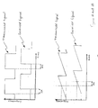
- the upper graph of Fig. 1A plots the change in frequency over time of a source microwave signal that has been transmitted through a bulk of material. As can be seen, the signal is transmitted in defined digital pulses, by which is meant that the signal commences and ends at defined points in time.
- the lower graph in Fig. 1A plots the same microwave signal as received by a receiving antenna after having been transmitted through a bulk of material.
- the velocity of signal transmission depends on the density of the material as well as the nature of the material in question.
- Fig. 1B An alternative method for measuring t is depicted in Fig. 1B.
- the signal pulse comprises continuously changing frequencies, rather than a single frequency.
- measurement of t can be achieved by comparing the timing of any particular frequency in both signals, as shown.
- a transmitted signal pulse comprising continuously changing frequencies, as illustrated in Fig. 1B, rather than a single frequency, is referred to as a "frequency modulated pulse”.
- the degree of attenuation of a received microwave signal is affected, in part, by the moisture content of the material through which the signal has been transmitted.
- Other factors influencing received signal attenuation are the nature of the material, its weight, its temperature and its density. It is therefore possible to calculate the moisture content of a material by analyzing several known parameters (i.e. the weight and temperature of the material, and empiric data describing the type of material) along with two measured parameters, namely, the t of a received microwave signal (from which can be calculated the density of the material at the point of measurement), and the attenuation of a received microwave signal.
- FIG. 2 shows an exemplary apparatus for performing the moisture measurements of the present invention.
- the apparatus includes a microwave radiation source 28, shown on one side of a module 10 of material under analysis.
- microwave radiation source 28 is a multiple-frequency transmitter for sequentially transmitting microwave radiation at a plurality of frequencies. The frequency to be transmitted is selected by a frequency controller 111.
- module 10 can be replaced with a continuous flow of bulk material without departing from the principles of the invention, however, for purposes of illustration, the apparatus will be described only with reference to module 10.
- Microwave radiation source 28 preferably includes at least one source antenna 30 for transmitting a source signal 32.
- source signal 32 is a very high frequency microwave signal in the form of a frequency modulated digital pulse.
- the preferred frequency for source signal 32 depends on the nature of the material being examined. For large modules, a frequency of 1.5-2 GHz is suitable. For average sized bales or cases of material, a frequency in the range of 3.5 GHz is suitable. For small cases of material, a frequency of 10-16 GHz is suitable. For bulk materials with low density, such as pharmaceutical powders, 16-30 GHz is suitable. For a single location in module 10 multiple pulses are transmitted by source antenna 30. Hereinafter, a group of multiple signal pulses transmitted through one location of module 10 will be said to constitute a "slice" or a "portion" of module 10, and multiple slices or portions will be said to make up an "area" of module 10.
- Source signal 32 is directed through module 10, and passes out of module 10 as an exit signal 34. As source signal 32 passes through module 10, source signal 32 is both attenuated and slowed. As mentioned above, the extent of this attenuation is determined by the density of the material of module 10 encountered by source signal 32, and by the moisture content of the material of module 10 encountered by source signal 32. The degree to which source signal 32 is slowed is determined by the density of module 10. Exit signal 34 is received by at least one receiving antenna 36 connected to a signal receiving unit 37. In a preferred embodiment, source antenna 30 and receiving antenna 36 are lens antennae. Suitable examples of lens antennae are a "horn antenna” (Malcam Ltd. Tel Aviv, Israel) and a "flat printed antenna” (MTI Ltd. Tel Aviv, Israel).
- An advantage to using a lens antenna is that the emitted microwave signal is more focused than the signal emitted by a regular antenna. A narrower, focused microwave beam enables the examination of lower density materials than can be examined using a regular antenna.
- Receiving antenna 36 is located on a substantially opposite side of module 10 relative to source antenna 30.
- signal receiving unit 37 includes a heterodyne receiver.
- Attenuation unit 40 includes an attenuation measurer 42, which compares the amplitude of antenna signal 38 to the known amplitude of source signal 32, thus measuring the attenuation of source signal 32 caused by its passing through the material of module 10.
- Time delay determiner 44 includes a reference receiver 118 which receives a reference signal 33 directly from microwave radiation source 28, via a cable. Reference signal 33 is thus identical to source signal 32 in terms of its timing and frequencies. Time delay determiner 44 compares reference signal 33 with antenna signal 38 so as to determine the time delay of antenna signal 38, that is, the degree to which source signal 32 was slowed while passing through module 10. In the preferred embodiment, the determination of the time delay of antenna signal 38 by time delay determiner 44 is achieved by utilizing a low pass filter and zero crossing. These techniques will be well known to one familiar with the art.
- the signal attenuation, as calculated by attenuation measurer 42, and the time delay, as calculated by time delay determiner 44, are then input to a processing unit 48.
- the attenuation and the time delay of antenna signal 38 are used by processing unit 48 to determine the moisture content and local density of module 10.
- the algorithms used to perform these calculations are described in Fig 4, below.
- a graphic or numeric output describing these parameters is then displayed on a display (not shown).
- Processing unit 48 sends a feedback signal 35, describing antenna signal 38, to microwave radiation source 28.
- microwave radiation source 28 changes the nature of source signal 32 so as to optimize antenna signal 38.
- Such optimization may include changing the frequency and/or the direction of the electric field density of source signal 32, and may be implemented, for example, so as to control background noise or minimize external radiofrequency interference (such as that generated by a nearby cellular phone).
- the signal attenuation is used to determine a raw moisture content (i.e. a moisture value which is uncorrected for the effect of density), while the signal time delay is used to determine the internal structure (i.e. the density) of the material under analysis. More specifically, it can be said that although the time delay of a signal alone cannot be translated into an absolute density value for a material, changes in the time delay of a signal do reflect changes in the density of that material. Thus if a standard density of a material and its associated time delay are known, any change in that density, relative to its standard density, can be calculated from a measured change in the signal time delay for that material.
- the signal attenuation is translated into a value for raw moisture content in accordance with empirical information derived from a database.
- An example of such a correlation is shown in Fig. 3.
- Empirically derived correlations of this nature must be generated for essentially all materials suitable for analysis by the current invention.
- Such correlations are empirically determined on a test material at a specific temperature and of a specific density.
- the actual temperature of the material at the time of analysis may differ from that of the test material used to derive the empiric correlation for that type of material. So too, the actual density of a material under analysis may differ from the density of the test material used to derive the appropriate empiric correlation.
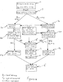
- Figure 4 shows a flow chart of the calculations for determining the moisture content and the internal structure (that is, the local density and variations in density) of the material in module 10 .
- the first step in the flow chart is the generation of an array of attenuation values (A) and an array of time delay values (t), as shown in step 1, by scanning an area of the material, that is, by generating multiple slices each consisting of a plurality of microwave pulses, as described above in Fig. 2. Several slices are grouped together as an "area", the moisture content and density of which it is desired to calculate.
- step 2 the data points in each array are filtered to remove any "edge” effects, the importance of which is illustrated below in Fig. 5. This results in filtered arrays A 2 and t 2 .
- the determination of whether a particular set of data points represents an edge effect can be made in a number of ways.
- the location of module 10 relative to source signal 32 can be determined, such that when an edge of module 10 is about to pass through source signal 32, a signal is sent to processing unit 48.
- the measurement of the attenuation can be plotted, and the data points corresponding to any artefactually high peaks or low troughs of attenuation can be eliminated, for example by removing any values which are more than two or three standard deviations from the average attenuation.
- the flow chart then branches into two parts.
- the right branch shows the steps used in calculating the raw moisture content of the material
- the left branch shows the steps used for the determination of the internal structure of the material.
- steps in the right (moisture content) branch will have the letter “a” appended; e.g., "3a”, "4a”, etc.
- steps in the left (internal structure) branch will have the letter "b” appended; e.g., "3b", "4b”, etc.
- step 3a the attenuation array for each slice is corrected for the effect of the shape of the module, the type of material being analyzed, and optionally for the density of the material.
- This correction is based upon empirically determined factors stored in a database, and produces an array A 3 of density, shape and type corrected attenuation values.
- optional density correction is achieved by comparing the measured gross weight of the module to a standard gross weight for a module of that size and type of material. Density correction is thus calculated by dividing the measured weight of the material into the standard weight value.
- the material under analysis is in the format of a continuous flow of bulk material, however, rather than individual modules, measurement of the gross weight of the area under analysis is not feasible. In this circumstance, or when it is decided not to correct for density of a module, the density of the material is assumed to be the same as the standard density stored in the database, and density correction is not performed.
- step 4a array A 3 is corrected for the current measured temperature of the material, to produce a temperature-corrected attenuation array A 4 for each slice.
- the function for this correction is proportional to 1 - Ts / Tt , where Ts is the standard temperature (stored in a database), and Tt is the measured temperature.
- Ts is the standard temperature (stored in a database)
- Tt is the measured temperature.
- the temperature-corrected attenuation array A 4 is thus compensated for the effect of measurements acquired at temperatures which differ from the temperature at which the empiric correlation, for that material type, was derived..
- step 4b determines whether the algorithm continues to step 5a or step 6".
- the algorithm continues to step 5a.
- the complete set of all attenuation values i.e. array A 4
- the algorithm continues to step 5a.
- the complete set of all attenuation values i.e. array A 4
- This calculation is performed according to a function which can be a linear integration of all the attenuation values for all the acquired slices, or else a polynomial, depending upon such empirical factors as the type of material being measured, the shape of the module and the structure of the module.
- This raw moisture value will be used in the determination of the true moisture value or content (by which is meant the raw moisture value corrected for the effect of material density) for the area of material under analysis.
- the true moisture value cannot be determined without knowing the actual density of material, which is calculated as shown in the left branch of the flow chart.
- the algorithm continues to step 6", which will be explained below.
- step 3b the density of each slice is calculated from the measured, filtered time delay array t 2 for each slice, in accordance with empirical information derived from a database.
- the empirical information includes the type of material, shape of the module (if relevant), a standard density for the material, and an empirical correlation between time delay and density.
- the empirical correlation between time delay and density is obtained by collecting time delay data from an analysis of a test material having known density, and then comparing the calculated density values with the true, known density values for the test material. From this analysis of the test material, the proper correlation between measured time delay values and calculated density values can be determined. Since this correlation depends upon the density and geometry of the test shape, and upon the nature of the material or materials from which the test shape is constructed, such an analysis must be performed for substantially every desired shape and material in order to obtain these essentially empirical correlations.
- step 4b the difference between the density of the current slice and that of previous slices is determined. Such deviations are important because they reveal irregularities in the internal structure of the material and/or the presence of foreign bodies located within the material. Based on the uniformity, or lack thereof, of density values for the slices constituting an area under analysis, the area is categorized as being of either uniform or non-uniform (by which is meant irregular) density.
- the density of the area of material is calculated by one of two different methods, depending upon whether the density of the area is categorized as being uniform or as being non-uniform. In the event that the deviation in the calculated densities for a plurality of slices is relatively small, the density is categorized as being uniform. A single mean density value is then calculated, and used to represent the density of the area. In step 6', the average density value and the average raw moisture value, which was calculated in step 5a, are combined to determine the true moisture value.
- the true moisture value is a function of the average density, the average raw moisture value, and an empirically determined correlation factor stored in a database. This correlation factor depends upon the type and structure of material, and is empirically determined through experimentation, as described above for the empiric correlation between time delay and density.
- the density is categorized as being non-uniform or irregular.
- the density value for each individual slice or portion is combined with the raw moisture value for each individual slice or portion (as calculated in step 4a) to determine an array of true moisture values for the individual slices constituting the area under analysis. This calculation is performed in a manner analogous to that described above for uniform density calculations, except that a plurality of density values, and preferably all density values, are used for the calculations.
- a density value for an individual slice or portion is hereinafter referred to as a "portion density value”
- a raw moisture value for an individual slice or portion is hereinafter referred to as a “portion raw moisture content value”.
- an average true moisture value for the area under analysis is then calculated as the mean of the array of true moisture values for the individual slices constituting the area under analysis.
- the true moisture value or values, and/or average true moisture value, calculated in steps 6', 6", and 7, are then output, for example by displaying on a display unit which could include a video screen, or by other apparatus for displaying the information.
- a warning to this effect is displayed on the display output (step 8). The reason for this warning is to alert the operator to the fact that the displayed moisture value has not been calculated from data derived from multiple slices (which is thus more accurate and less influenced by random error) but rather, it has been calculated from data derived from a single slice only (and is thus less accurate and more sensitive to error).
- a second system 26 may be deployed in an orientation which is orthogonal to that of a first system 26, so as to calculate moisture and density data for slices through module 10, such that such slices are orthogonal to and coordinated with the slices scanned by the first system 26.
- the resultant density and moisture data from the plurality of intersecting slices can be correlated with each other by processing unit 48 so as to generate 2 or 3 dimensional maps of density and moisture within the material being analyzed.
- a potential source of inaccuracy in the calculation of signal attenuation may arise due to microwave signals which have undergone multiple reflections within and around module 10, including reflections off of source antenna 30, being received by signal receiving unit 37. Such microwaves will hereinafter be referred to as "scattered" microwaves.
- the attenuation of scattered microwaves does not provide an accurate depiction of the moisture content within module 10.
- Scattered microwaves originating from a given pulse of microwave radiation may be identified by the fact that they are received by receiving unit 37 later than non-scattered microwaves originating from the same microwave pulse.
- a reference time delay value which predicts when non-scattered microwaves will be received by signal receiving unit 37, can be empirically determined for essentially any material type and shape, and stored in a database. Microwave signals received at a point in time NOT predicted by the reference time delay value can therefore be assumed to be scattered microwaves.
- Attenuation measurer 40 accesses a database of reference time delay values and a scatter determiner module (not shown) in attenuation measurer 40, and compares the actual time delay of the received signal to a reference time delay value, so as to determine whether the received microwave signals are scattered or not. Only non-scattered microwaves are then processed by attenuation measurer 40. In this way, the number of distorted microwave signals analyzed by attenuation measurer 40 when determining the attenuation of received microwaves can be minimized.
- Equation describing the relationship between time delay and material density are as follows. Note that F is the frequency of the microwave radiation; l is the length of the beam path as it passes through the material of the module; ⁇ ' (or ⁇ ) is the dielectric constant of the bulk of material; ⁇ " (or ⁇ ") is the attenuation constant of a bulk material under analysis; ⁇ 0 (or ⁇ 0 ) is the vacuum dielectric constant; ⁇ t is the time delay of a microwave signal after passing through a material under analysis; C is the speed of microwaves through a material under analysis; C o is the speed of reference signal 35 as reference receiver 118 ( ⁇ speed of light); d is the density of a material under analysis; m is the moisture of a material under analysis; ⁇ is the wavelength of the microwave radiation; and f represents the phrase "is a function of York.
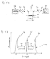
- FIG. 5 is an illustration of edge effects and foreign body effects on attenuation data derived from multiple microwave slices through module 10. Similar effects are encountered for time delay data as well.
- Fig. 5A shows module 10 moving in direction V between microwave radiation source 28, which emits source signal 32, and receiving antenna 36, which receives exit signal 34.
- a foreign body 91 is within module 10.
- the length of module 10 is from point A to point C.
- Fig. 5B shows a graph 99 of the measured attenuation obtained substantially for all slices along the length of module 10.
- a first peak 94 occurs as module 10 first enters source signal 32, corresponding to a slice between points A and A', and is artefactually high due to a leading edge effect. So too a peak 96 is caused by the trailing edge of module 10, at slice C-C', as module 10 leaves source signal 32.
- a slice B-B' passing through foreign body 91 causes an artefact 95.
- peaks 94 and 96 are artefactual, they cannot be used for determining the corrected attenuation, and hence the raw moisture value, as described in Fig. 4 above, and are thus filtered out as described in step 2 of Fig. 4.
- the data points which are used for determining the attenuation are taken from between peaks 94, 95, and 96, as shown by box 98 and box 100.
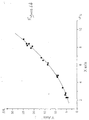
- Figures 6A and 6B demonstrate the importance of selecting a particular portion of the measured attenuation for calculating the moisture of the material.
- the curve shows the relationship between true moisture values (plotted along the X-axis) and the measured attenuation obtained from one of the artefactually high peaks described in Figure 5 (plotted on the Y-axis).
- Figure 6B shows the relationship between true moisture values (on the X-axis) and the measured attenuation (on the Y-axis) obtained from an area between the peaks, as for example box 100.
- the measured attenuation is an accurate reflection of the true moisture content of a material only when artefactual measurements, such as those caused by leading or trailing edge effects or foreign bodies, are filtered out.
Landscapes
- Physics & Mathematics (AREA)
- Electromagnetism (AREA)
- Health & Medical Sciences (AREA)
- Life Sciences & Earth Sciences (AREA)
- Chemical & Material Sciences (AREA)
- Analytical Chemistry (AREA)
- Biochemistry (AREA)
- General Health & Medical Sciences (AREA)
- General Physics & Mathematics (AREA)
- Immunology (AREA)
- Pathology (AREA)
- Investigating Or Analysing Materials By Optical Means (AREA)
- Investigating Or Analyzing Materials By The Use Of Electric Means (AREA)
Claims (11)
- Ein Verfahren zur Bestimmung eines Feuchtigkeitsgehalts eines Materials, wobei das Verfahren folgende Schritte umfasst:(a) Übertragen von Mikrowellen, deren Frequenz sich mit der Zeit verändert, durch einen Abschnitt des Materials;(b) Empfangen der übertragenen Mikrowellen, nachdem die übertragenen Mikrowellen aus dem Abschnitt des Materials ausgetreten sind;(c) Bestimmen eines erreichten Dämpfungswerts und eines erreichten Zeitverzögerungswerts der empfangenen Mikrowellen im Verhältnis zu den übertragenen Mikrowellen;(d) Wiederholen der Schritte (a) bis (c) für eine Vielzahl von Abschnitten des Materials, sodass eine Vielzahl erreichter Dämpfungswerte und eine Vielzahl erreichter Zeitverzögerungswerte erhalten werden;(e) Berechnen eines Roh-Feuchtigskeitsgehaltswerts aus einem Dämpfungswert für jeden der Vielzahl von Abschnitten des Materials, sodass eine Vielzahl von Abschnitts-Roh-Feuchtigkeitsgehaltswerten erhalten wird;(f) Berechnen eines Dichtewerts aus einem Zeitverzögerungswert für jeden der Vielzahl von Abschnitten des Materials, sodass eine Vielzahl von Abschnitts-Dichtewerten erhalten wird;(g) Vergleichen jedes der Abschnitts-Dichtewerte mit jedem anderen der Abschnitts-Dichtewerte, um eine Regelmäßigkeit einer Struktur des Materials zu bestimmen, wobei die Struktur als unregelmäßig eingestuft wird, wenn einer der Abschnitts-Dichtewerte sich wesentlich von einem anderen der Abschnitts-Dichtewerte unterscheidet;(h) Berechnen eines durchschnittlichen wahren Feuchtigkeitsgehalts des Materials aus der Vielzahl von Abschnitts-Roh-Feuchtigkeitsgehaltswerten und aus der Vielzahl von Abschnitts-Dichtewerten des Materials.
- Das Verfahren von Anspruch 1, das weiter folgende Schritte umfasst:(i) Korrektur der Vielzahl erreichter Dämpfungswerte nach der Dichte des Materials, Temperatur des Materials, Art des Materials und Struktur des Materials durch Verwendung mindestens eines empirischen Faktors, sodass eine Vielzahl korrigierter Dämpfungswerte erhalten wird;(j) Korrektur der Vielzahl erreichter Zeitverzögerungswerte nach Art des Materials und einer Standard-Dichte des Materials durch Verwendung mindestens eines empirischen Faktors, sodass eine Vielzahl korrigierter Zeitverzögerungswerte erhalten wird;(k) Berechnen eines korrigierten Roh-Feuchtigkeitsgehalts des Materials aus der Vielzahl korrigierter Dämpfungswerte;(l) Berechnen einer korrigierten Dichte des Materials aus der Vielzahl korrigierter Zeitverzögerungswerte; und(m) Berechnen eines korrigierten wahren Feuchtigkeitsgehalts des Materials aus dem korrigierten Roh-Feuchtigkeitsgehalt und aus der korrigierten Dichte des Materials.
- Das Verfahren von Anspruch 1, worin der Abschnitt des Materials Teil eines Moduls des Materials ist.
- Das Verfahren von Anspruch 3, das weiter den Schritt des Filterns der Vielzahl erreichter Zeitverzögerungswerte und der Vielzahl erreichter Dämpfungswerte zum Entfernen von Artefakt-Werten umfasst, die durch die Vielzahl von Mikrowellen erzeugt wurden, welche durch einen Rand des Moduls hindurchgedrungen sind.
- Das Verfahren von Anspruch 1, worin der Abschnitt des Materials Teil eines Massendurchflusses des Materials ist.
- Das Verfahren von Anspruch 1, worin, wenn ermittelt wird, dass die Struktur unregelmäßig ist, ein wahrer Feuchtigkeitsgehalt aus der Vielzahl von Abschnitts-Dichtewerten und aus der Vielzahl von Abschnitts-Roh-Feuchtigkeitsgehaltswerten für jeden der Vielzahl von Abschnitten des Materials berechnet wird.
- Das Verfahren von Anspruch 1, worin die übertragenen Mikrowellen als digitaler Impuls von Mikrowellen mit Meterwellen-Hochfrequenz übertragenen werden.
- Das Verfahren von Anspruch 7, worin die Frequenz des digitalen Impulses sich kontinuierlich ändert.
- Das Verfahren von Anspruch 1, worin der Roh-Feuchtigkeitsgehalt des Materials aus der Vielzahl erreichter Dämpfungswerte unter Verwendung einer empirisch abgeleiteten Korrelation zwischen der Signaldämpfung und dem Feuchtigkeitsgehalt des Materials berechnet wird.
- Das Verfahren von Anspruch 1, worin das Material gewählt ist aus der Gruppe bestehend aus Baumwollfaser, Seidenfaser, Wollfaser, pharmazeutischem Material, Samen, Papier, Tabak und synthetischer Faser.
- Das Verfahren von Anspruch 1, das weiter folgenden Schritt umfasst:(k) Bereitstellen eines Referenz-Zeitverzögerungswerts; und(l) Identifikation gestreuter Mikrowellen innerhalb der empfangenen Mikrowellen durch Vergleichen der erhaltenen Zeitverzögerung mit dem Referenz-Zeitverzögerungswert.
Applications Claiming Priority (2)
| Application Number | Priority Date | Filing Date | Title |
|---|---|---|---|
| US4780 | 1998-01-09 | ||
| US09/004,780 US6111415A (en) | 1998-01-09 | 1998-01-09 | Device and method for determining the moisture content of a bulk material |
Publications (3)
| Publication Number | Publication Date |
|---|---|
| EP0935136A2 EP0935136A2 (de) | 1999-08-11 |
| EP0935136A3 EP0935136A3 (de) | 2003-03-05 |
| EP0935136B1 true EP0935136B1 (de) | 2006-07-05 |
Family
ID=21712496
Family Applications (1)
| Application Number | Title | Priority Date | Filing Date |
|---|---|---|---|
| EP99100142A Expired - Lifetime EP0935136B1 (de) | 1998-01-09 | 1999-01-08 | Verfahren zur Erfassung der Feuchtigkeit eines Schüttgutes |
Country Status (4)
| Country | Link |
|---|---|
| US (1) | US6111415A (de) |
| EP (1) | EP0935136B1 (de) |
| AT (1) | ATE332500T1 (de) |
| DE (1) | DE69932194T2 (de) |
Cited By (1)
| Publication number | Priority date | Publication date | Assignee | Title |
|---|---|---|---|---|
| CN111929332A (zh) * | 2020-09-29 | 2020-11-13 | 潍坊力创电子科技有限公司 | 基于微波在线水分检测仪的自动加水装置及其控制系统 |
Families Citing this family (31)
| Publication number | Priority date | Publication date | Assignee | Title |
|---|---|---|---|---|
| US6107809A (en) * | 1995-07-18 | 2000-08-22 | Malcam Ltd. | Device and method for determining the moisture content of tobacco |
| US6987393B2 (en) * | 2001-08-24 | 2006-01-17 | Rhino Analytics, L.P. | Ultra-wide band pulse dispersion spectrometry method and apparatus providing multi-component composition analysis |
| FR2833080B1 (fr) * | 2001-12-05 | 2004-10-29 | France Etat Ponts Chaussees | Procede de determination de la teneur en eau d'un materiau et dispositif de mesure |
| ITBO20020432A1 (it) * | 2002-07-04 | 2004-01-05 | Ima Spa | Metodo per il rilevamento ed il controllo di caratteristiche di articoli farmaceutici |
| US7330034B1 (en) | 2003-12-31 | 2008-02-12 | The United States Of America As Represented By The Secretary Of Agriculture | Moisture measurement system for seed cotton or lint |
| US7078913B1 (en) | 2003-12-31 | 2006-07-18 | The United States Of America As Represented By The Secretary Of Agriculture | Multipath resistant microwave moisture sensor |
| US7075309B2 (en) * | 2004-03-08 | 2006-07-11 | Livewire Test Labs, Inc. | System and method to locate an anomaly of a conductor |
| EP1751561A2 (de) * | 2004-04-26 | 2007-02-14 | Malcam Ltd. | Bidirektionales dreidimensionales mikrowellen-scannen und volumetrische abbildung einer ganzen rolle oder palette papier |
| US7278186B2 (en) * | 2005-01-05 | 2007-10-09 | Uster Technologies Ag | Ultra low frequency moisture sensor |
| FI119526B (fi) * | 2005-05-17 | 2008-12-15 | Senfit Oy | Menetelmä ja mittalaite mitata vesipitoisuutta |
| CN100395541C (zh) * | 2005-06-10 | 2008-06-18 | 东华大学 | 一种浆纱回潮率检测系统 |
| US9572511B2 (en) | 2007-09-05 | 2017-02-21 | Sensible Medical Innovations Ltd. | Methods and systems for monitoring intrabody tissues |
| JP2010537766A (ja) | 2007-09-05 | 2010-12-09 | センシブル メディカル イノヴェイションズ リミテッド | ユーザの組織を監視するために電磁放射を使用するための方法、システム、および装置 |
| DE102007057092B4 (de) | 2007-11-20 | 2009-08-06 | Tews Elektronik Dipl.-Ing. Manfred Tews | Verfahren und Vorrichtung zur Feuchte- und/oder Dichtemessung |
| US10667715B2 (en) | 2008-08-20 | 2020-06-02 | Sensible Medical Innovations Ltd. | Methods and devices of cardiac tissue monitoring and analysis |
| CN101776617B (zh) * | 2009-01-12 | 2012-03-21 | 中国农业机械化科学研究院 | 一种微波在线式粮食水分检测装置及其方法 |
| CN101907578B (zh) * | 2009-06-05 | 2014-05-21 | 西安阿尔特水分检测技术有限公司 | 一种微波法棉花回潮率在线测量系统的实现方法 |
| CN101907579B (zh) * | 2009-06-05 | 2014-07-02 | 西安阿尔特水分检测技术有限公司 | 一种微波法棉花回潮率在线测量系统 |
| US8907682B2 (en) * | 2009-07-30 | 2014-12-09 | Sensible Medical Innovations Ltd. | System and method for calibration of measurements of interacted EM signals in real time |
| ES2385942B1 (es) * | 2010-06-09 | 2013-06-13 | Centro De Investigación Y Tecnología Agroalimentaria De Aragón (Cita) | Dispositivo de medida del contenido en agua de elementos laminares. |
| CN102590232B (zh) * | 2011-01-18 | 2014-06-04 | 丹东东方测控技术股份有限公司 | 在线微波水分仪水分检测的非线性性自动校正方法 |
| US9128494B2 (en) | 2011-11-17 | 2015-09-08 | Microsemi Corporation | Apparatus and method for assessing volumetric moisture content and controlling an irrigator |
| WO2014052715A1 (en) * | 2012-09-27 | 2014-04-03 | Magnetrol International, Incorporated | Time domain reflectometry based method for emulsion detection and profiling |
| AT14962U1 (de) * | 2014-11-13 | 2016-09-15 | Dunakontroll Irányitástechnikai Kft | Hochfrequenzmesssystem zum Messen des Feuchtigkeitsgehalts von Papier und verschiedenen faserhaltigen Materialien |
| FR3033644B1 (fr) * | 2015-03-11 | 2017-04-21 | Bostik Sa | Mesure non-destructive du taux d'humidite d'un materiau |
| US10422742B2 (en) * | 2017-10-18 | 2019-09-24 | The Boeing Company | Moisture detection system |
| US10656081B2 (en) | 2017-10-18 | 2020-05-19 | The Boeing Company | Synchronized phased array and infrared detector system for moisture detection |
| EP3674703A1 (de) * | 2018-12-31 | 2020-07-01 | INESC TEC - Instituto de Engenharia de Sistemas e Computadores, Tecnologia e Ciência | Verfahren und vorrichtung zur messung von in vegetation vorhandenem wasser |
| US12000788B1 (en) | 2020-01-10 | 2024-06-04 | Gold Bond Building Products, Llc | Inline detection of gypsum panel calcination |
| CN115460907A (zh) * | 2020-04-27 | 2022-12-09 | 昕诺飞控股有限公司 | 园艺系统和方法 |
| WO2023132288A1 (ja) * | 2022-01-05 | 2023-07-13 | ソニーグループ株式会社 | 情報処理装置、情報処理方法及び情報処理プログラム |
Family Cites Families (27)
| Publication number | Priority date | Publication date | Assignee | Title |
|---|---|---|---|---|
| US2659860A (en) * | 1949-08-27 | 1953-11-17 | Inst Textile Tech | Method and apparatus for measuring moisture content |
| US3360721A (en) * | 1963-10-30 | 1967-12-26 | Liggett & Myers Tobacco Co | Determination of moisture in tobacco |
| US3644826A (en) * | 1967-04-03 | 1972-02-22 | Industrial Nucleonics Corp | Moisture-measuring system using microwave and nucleonic measurements |
| GB1431762A (en) * | 1972-04-05 | 1976-04-14 | Bosisio R G | Method and apparatus |
| US3815019A (en) * | 1972-12-19 | 1974-06-04 | Electronic Ass Of Ca Ltd | Microwave low moisture measuring apparatus |
| US3810005A (en) * | 1973-03-26 | 1974-05-07 | Ind Dev Design | Flaw detection system using microwaves |
| US4123702A (en) * | 1976-02-13 | 1978-10-31 | Ilmari Kinanen | Method for classifying and measuring of timbers |
| DE2808739C2 (de) * | 1978-03-01 | 1983-11-10 | Bergwerksverband Gmbh, 4300 Essen | Schnellmeßverfahren zur Konzentrationsbestimmung der polaren Komponente von ansonsten nichtpolaren Stoffen |
| FI57490C (fi) * | 1978-06-01 | 1980-08-11 | Innotec Oy | Foerfarande foer bestaemning av snedfibrigheten i virke i synnerhet i saogat virke |
| DE2928487A1 (de) * | 1979-07-14 | 1981-02-05 | Philips Patentverwaltung | Verfahren zur messung der relativen feuchte eines messgutes mit hilfe von mikrowellen im ghz-bereich |
| US4352059A (en) * | 1980-06-13 | 1982-09-28 | Massachusetts Institute Of Technology | Determination of moisture level in materials |
| DE3150202A1 (de) * | 1981-12-18 | 1983-06-23 | Philips Patentverwaltung Gmbh, 2000 Hamburg | Anordnung zur messung der feuchte |
| SU1149150A1 (ru) * | 1982-12-10 | 1985-04-07 | Ташкентское Научно-Производственное Объединение "Сигнал" | Устройство дл измерени влажности диэлектрических материалов |
| JPS59197843A (ja) * | 1983-04-26 | 1984-11-09 | Yokogawa Hokushin Electric Corp | マイクロ波水分計 |
| SE449139B (sv) * | 1984-06-27 | 1987-04-06 | Stiftelsen Inst Mikrovags | Sett att meta fuktkvot i organiska material jemte anordning derfor |
| US4578998A (en) * | 1985-03-08 | 1986-04-01 | Armstrong World Industries, Inc. | Microwave moisture measurement |
| US4789820A (en) * | 1986-01-08 | 1988-12-06 | Hercules Incorporated | Apparatus and method for sensing multiple parameters of sheet material |
| US4727311A (en) * | 1986-03-06 | 1988-02-23 | Walker Charles W E | Microwave moisture measurement using two microwave signals of different frequency and phase shift determination |
| US4962384A (en) * | 1986-03-06 | 1990-10-09 | Walker Charles W E | Microwave antenna apparatus |
| US4991915A (en) * | 1988-08-04 | 1991-02-12 | Imperial Chemical Industries PLC Manchester Polytechnic | Microwave moisture sensing arrangement |
| US5315258A (en) * | 1989-01-13 | 1994-05-24 | Kajaani Elektroniikka Oy | Method and apparatus for determining the moisture content of a material |
| US5619143A (en) * | 1989-02-14 | 1997-04-08 | Commonwealth Scientific And Industrial Research Organisation | Microwave scanning apparatus |
| CA2063717C (en) * | 1989-08-15 | 2002-10-08 | Nicholas George Cutmore | Moisture content by microwave phase shift and mass/area |
| JP3160474B2 (ja) * | 1994-09-12 | 2001-04-25 | 株式会社東芝 | マイクロ波濃度計 |
| DK171153B1 (da) * | 1995-02-10 | 1996-07-01 | Slagteriernes Forskningsinst | Fremgangsmåde og anlæg ved blanding af et uensartet, strømningsdygtigt fødevare-, foder- eller farmaceutisk materiale samt indretning til udtagelse afprøver |
| US5845529A (en) * | 1995-07-18 | 1998-12-08 | Malcam Ltd. | Device and method for determining the moisture content of material |
| US5621330A (en) * | 1995-07-18 | 1997-04-15 | Malcam Ltd. | Device and method for determining the moisture content of a bale of material with multiple layers |
-
1998
- 1998-01-09 US US09/004,780 patent/US6111415A/en not_active Expired - Lifetime
-
1999
- 1999-01-08 EP EP99100142A patent/EP0935136B1/de not_active Expired - Lifetime
- 1999-01-08 AT AT99100142T patent/ATE332500T1/de not_active IP Right Cessation
- 1999-01-08 DE DE69932194T patent/DE69932194T2/de not_active Expired - Lifetime
Cited By (1)
| Publication number | Priority date | Publication date | Assignee | Title |
|---|---|---|---|---|
| CN111929332A (zh) * | 2020-09-29 | 2020-11-13 | 潍坊力创电子科技有限公司 | 基于微波在线水分检测仪的自动加水装置及其控制系统 |
Also Published As
| Publication number | Publication date |
|---|---|
| DE69932194D1 (de) | 2006-08-17 |
| DE69932194T2 (de) | 2007-06-14 |
| US6111415A (en) | 2000-08-29 |
| ATE332500T1 (de) | 2006-07-15 |
| EP0935136A2 (de) | 1999-08-11 |
| EP0935136A3 (de) | 2003-03-05 |
Similar Documents
| Publication | Publication Date | Title |
|---|---|---|
| EP0935136B1 (de) | Verfahren zur Erfassung der Feuchtigkeit eines Schüttgutes | |
| AU734830B2 (en) | Determining moisture content by using microwaves phase and attentuation | |
| JP3624160B2 (ja) | ばらおよびパッケージ化されたタバコの湿分ならびに密度の非侵入性測定ならびに決定のための装置および方法 | |
| EP0950177B1 (de) | Gerät zur Bestimmung des Feuchtigkeitsgehalts eines Materials | |
| US5397993A (en) | Method for measuring the material moisture content of a material under test using microwaves | |
| EP1114299A1 (de) | Mikrowellenresonator zur kontinuierlichen ausweitung von faserigen stoffen | |
| JPS60135752A (ja) | マイクロ波水分計 | |
| EP0390623A2 (de) | Optische Anordnung zur Ermittlung von Eigenschaften bei sich bewegendem folienartigem Material | |
| DE102017207648A1 (de) | Verfahren und Vorrichtung zur Messung einer Schichtdicke eines Objekts | |
| US7679375B2 (en) | System and method for detecting foreign objects in a product | |
| US4942363A (en) | Apparatus and method for measuring two properties of an object using scattered electromagnetic radiation | |
| WO2000014552A1 (en) | Moisture measurement device using microwaves | |
| CA1124326A (en) | Microwave moisture-profile gauge | |
| EP0967479A2 (de) | Verfahren und Vorrichtung zur Dichtemessung einer Substanz mit Kompensierung des freien Wassers | |
| US20010052986A1 (en) | Systems and methods for non-destructive mass sensing | |
| CN110446919B (zh) | 非破坏性检测方法和非破坏性检测装置 | |
| AU770854B2 (en) | Apparatus and method for detection of foreign bodies in products | |
| JPH06300689A (ja) | 透過法による青果物の内部品質測定法 | |
| CN113970522A (zh) | 一种在线分析用于生产吸收性卫生用品的机器中的复合产品的方法 | |
| JPH11344441A (ja) | 青果物内部品質測定装置及び測定方法 |
Legal Events
| Date | Code | Title | Description |
|---|---|---|---|
| PUAI | Public reference made under article 153(3) epc to a published international application that has entered the european phase |
Free format text: ORIGINAL CODE: 0009012 |
|
| AK | Designated contracting states |
Kind code of ref document: A2 Designated state(s): AT BE CH CY DE DK ES FI FR GB GR IE IT LI LU MC NL PT SE |
|
| AX | Request for extension of the european patent |
Free format text: AL;LT;LV;MK;RO;SI |
|
| RIC1 | Information provided on ipc code assigned before grant |
Free format text: 7G 01N 22/04 A, 7G 01N 22/00 B |
|
| PUAL | Search report despatched |
Free format text: ORIGINAL CODE: 0009013 |
|
| AK | Designated contracting states |
Kind code of ref document: A3 Designated state(s): AT BE CH CY DE DK ES FI FR GB GR IE IT LI LU MC NL PT SE |
|
| AX | Request for extension of the european patent |
Extension state: AL LT LV MK RO SI |
|
| RAP1 | Party data changed (applicant data changed or rights of an application transferred) |
Owner name: MALCAM LTD. |
|
| 17P | Request for examination filed |
Effective date: 20030701 |
|
| AKX | Designation fees paid |
Designated state(s): AT BE CH DE ES FI FR GB IT LI NL SE |
|
| 17Q | First examination report despatched |
Effective date: 20050630 |
|
| GRAP | Despatch of communication of intention to grant a patent |
Free format text: ORIGINAL CODE: EPIDOSNIGR1 |
|
| RTI1 | Title (correction) |
Free format text: METHOD FOR DETERMINING THE MOISTURE CONTENT OF A BULK MATERIAL |
|
| GRAS | Grant fee paid |
Free format text: ORIGINAL CODE: EPIDOSNIGR3 |
|
| GRAA | (expected) grant |
Free format text: ORIGINAL CODE: 0009210 |
|
| AK | Designated contracting states |
Kind code of ref document: B1 Designated state(s): AT BE CH DE ES FI FR GB IT LI NL SE |
|
| PG25 | Lapsed in a contracting state [announced via postgrant information from national office to epo] |
Ref country code: NL Free format text: LAPSE BECAUSE OF FAILURE TO SUBMIT A TRANSLATION OF THE DESCRIPTION OR TO PAY THE FEE WITHIN THE PRESCRIBED TIME-LIMIT Effective date: 20060705 Ref country code: IT Free format text: LAPSE BECAUSE OF FAILURE TO SUBMIT A TRANSLATION OF THE DESCRIPTION OR TO PAY THE FEE WITHIN THE PRESCRIBED TIME-LIMIT;WARNING: LAPSES OF ITALIAN PATENTS WITH EFFECTIVE DATE BEFORE 2007 MAY HAVE OCCURRED AT ANY TIME BEFORE 2007. THE CORRECT EFFECTIVE DATE MAY BE DIFFERENT FROM THE ONE RECORDED. Effective date: 20060705 Ref country code: FI Free format text: LAPSE BECAUSE OF FAILURE TO SUBMIT A TRANSLATION OF THE DESCRIPTION OR TO PAY THE FEE WITHIN THE PRESCRIBED TIME-LIMIT Effective date: 20060705 Ref country code: BE Free format text: LAPSE BECAUSE OF FAILURE TO SUBMIT A TRANSLATION OF THE DESCRIPTION OR TO PAY THE FEE WITHIN THE PRESCRIBED TIME-LIMIT Effective date: 20060705 Ref country code: AT Free format text: LAPSE BECAUSE OF FAILURE TO SUBMIT A TRANSLATION OF THE DESCRIPTION OR TO PAY THE FEE WITHIN THE PRESCRIBED TIME-LIMIT Effective date: 20060705 |
|
| REG | Reference to a national code |
Ref country code: GB Ref legal event code: FG4D |
|
| REG | Reference to a national code |
Ref country code: CH Ref legal event code: EP |
|
| REF | Corresponds to: |
Ref document number: 69932194 Country of ref document: DE Date of ref document: 20060817 Kind code of ref document: P |
|
| PG25 | Lapsed in a contracting state [announced via postgrant information from national office to epo] |
Ref country code: SE Free format text: LAPSE BECAUSE OF FAILURE TO SUBMIT A TRANSLATION OF THE DESCRIPTION OR TO PAY THE FEE WITHIN THE PRESCRIBED TIME-LIMIT Effective date: 20061005 |
|
| PG25 | Lapsed in a contracting state [announced via postgrant information from national office to epo] |
Ref country code: ES Free format text: LAPSE BECAUSE OF FAILURE TO SUBMIT A TRANSLATION OF THE DESCRIPTION OR TO PAY THE FEE WITHIN THE PRESCRIBED TIME-LIMIT Effective date: 20061016 |
|
| REG | Reference to a national code |
Ref country code: CH Ref legal event code: NV Representative=s name: MARK-PAT MODIANO S.A. |
|
| NLV1 | Nl: lapsed or annulled due to failure to fulfill the requirements of art. 29p and 29m of the patents act | ||
| ET | Fr: translation filed | ||
| PLBE | No opposition filed within time limit |
Free format text: ORIGINAL CODE: 0009261 |
|
| STAA | Information on the status of an ep patent application or granted ep patent |
Free format text: STATUS: NO OPPOSITION FILED WITHIN TIME LIMIT |
|
| 26N | No opposition filed |
Effective date: 20070410 |
|
| PGFP | Annual fee paid to national office [announced via postgrant information from national office to epo] |
Ref country code: CH Payment date: 20140130 Year of fee payment: 16 Ref country code: DE Payment date: 20140131 Year of fee payment: 16 |
|
| PGFP | Annual fee paid to national office [announced via postgrant information from national office to epo] |
Ref country code: FR Payment date: 20140130 Year of fee payment: 16 |
|
| PGFP | Annual fee paid to national office [announced via postgrant information from national office to epo] |
Ref country code: GB Payment date: 20140130 Year of fee payment: 16 |
|
| REG | Reference to a national code |
Ref country code: DE Ref legal event code: R119 Ref document number: 69932194 Country of ref document: DE |
|
| REG | Reference to a national code |
Ref country code: CH Ref legal event code: PL |
|
| GBPC | Gb: european patent ceased through non-payment of renewal fee |
Effective date: 20150108 |
|
| PG25 | Lapsed in a contracting state [announced via postgrant information from national office to epo] |
Ref country code: DE Free format text: LAPSE BECAUSE OF NON-PAYMENT OF DUE FEES Effective date: 20150801 Ref country code: CH Free format text: LAPSE BECAUSE OF NON-PAYMENT OF DUE FEES Effective date: 20150131 Ref country code: LI Free format text: LAPSE BECAUSE OF NON-PAYMENT OF DUE FEES Effective date: 20150131 Ref country code: GB Free format text: LAPSE BECAUSE OF NON-PAYMENT OF DUE FEES Effective date: 20150108 |
|
| REG | Reference to a national code |
Ref country code: FR Ref legal event code: ST Effective date: 20150930 |
|
| PG25 | Lapsed in a contracting state [announced via postgrant information from national office to epo] |
Ref country code: FR Free format text: LAPSE BECAUSE OF NON-PAYMENT OF DUE FEES Effective date: 20150202 |