EP0935023B1 - Bodenverdichtungsvorrichtung und Verfahren zur Steuerung ihres Lenkantriebes - Google Patents
Bodenverdichtungsvorrichtung und Verfahren zur Steuerung ihres Lenkantriebes Download PDFInfo
- Publication number
- EP0935023B1 EP0935023B1 EP99102125A EP99102125A EP0935023B1 EP 0935023 B1 EP0935023 B1 EP 0935023B1 EP 99102125 A EP99102125 A EP 99102125A EP 99102125 A EP99102125 A EP 99102125A EP 0935023 B1 EP0935023 B1 EP 0935023B1
- Authority
- EP
- European Patent Office
- Prior art keywords
- steering
- wheel
- travel
- control device
- wheels
- Prior art date
- Legal status (The legal status is an assumption and is not a legal conclusion. Google has not performed a legal analysis and makes no representation as to the accuracy of the status listed.)
- Expired - Lifetime
Links
- 238000000034 method Methods 0.000 title claims description 15
- 239000002689 soil Substances 0.000 title claims description 13
- 238000005056 compaction Methods 0.000 claims description 8
- 238000006073 displacement reaction Methods 0.000 claims 1
- 230000009977 dual effect Effects 0.000 claims 1
- 238000010586 diagram Methods 0.000 description 1
- 230000003993 interaction Effects 0.000 description 1
- 208000013409 limited attention Diseases 0.000 description 1
- 230000007935 neutral effect Effects 0.000 description 1
- 238000005096 rolling process Methods 0.000 description 1
Images


Classifications
-
- B—PERFORMING OPERATIONS; TRANSPORTING
- B62—LAND VEHICLES FOR TRAVELLING OTHERWISE THAN ON RAILS
- B62D—MOTOR VEHICLES; TRAILERS
- B62D33/00—Superstructures for load-carrying vehicles
- B62D33/06—Drivers' cabs
- B62D33/063—Drivers' cabs movable from one position into at least one other position, e.g. tiltable, pivotable about a vertical axis, displaceable from one side of the vehicle to the other
- B62D33/073—Drivers' cabs movable from one position into at least one other position, e.g. tiltable, pivotable about a vertical axis, displaceable from one side of the vehicle to the other characterised by special adaptations of vehicle control devices
-
- E—FIXED CONSTRUCTIONS
- E01—CONSTRUCTION OF ROADS, RAILWAYS, OR BRIDGES
- E01C—CONSTRUCTION OF, OR SURFACES FOR, ROADS, SPORTS GROUNDS, OR THE LIKE; MACHINES OR AUXILIARY TOOLS FOR CONSTRUCTION OR REPAIR
- E01C19/00—Machines, tools or auxiliary devices for preparing or distributing paving materials, for working the placed materials, or for forming, consolidating, or finishing the paving
- E01C19/22—Machines, tools or auxiliary devices for preparing or distributing paving materials, for working the placed materials, or for forming, consolidating, or finishing the paving for consolidating or finishing laid-down unset materials
- E01C19/23—Rollers therefor; Such rollers usable also for compacting soil
- E01C19/26—Rollers therefor; Such rollers usable also for compacting soil self-propelled or fitted to road vehicles
Definitions
- the invention relates to a Wegbandagige soil compacting device with double steering, in particular a road roller with double-disc steering, and a method for controlling its steering and Travel drive, the steering drive both separately controllable Roller bandages of a control device in dependence of from the roller guide selected steering specifications and / or the steering mode controlled as described in US-A-4 043 422.
- the object of the present invention is to Working with the road rollers of the aforementioned. To further simplify Art, thereby increasing productivity to achieve.
- control device controls the steering drive of both bandages during or after a change of direction such that by the steering drive in the direction of travel rear bandage as passive bandage in the respective zero position is transferred.
- the inventive method of automatic switching leads but not only to improve the ease of use for the roller guide is, but that in particular the reliability of the Road roller is increased by the roller guide now fully on the Steering can always focus on the same steering mode and yourself not every time you change your driving, on the one hand to a different steering mode set and on the other in addition to switching the The direction of travel must also manually switch the steering mode.
- the control device switches on and / or after entering a direction change, the driving of the steering gears the bandages, with the switching either carried out immediately can be such that the direction of change before the front, active bandage now as a rear, passive bandage is controlled and transferred to the zero position, while the before the Change rear, passive in zero position bandage afterwards as active, front bandage according to the respective steering specification is controlled.
- the control device does that Switching the bandages successively in such a way that after the Change of direction rear bandage as long as active bandage is driven until it reaches a preset value, whereupon then the switched control the rear drum as passive and the front bandage drives as active bandage, with up to Switching the front bandage is passive and in its neutral position remains.
- this preset, switching the bandages triggering Value is concerned, this may be, for example, the steering position or the steering angle in the direction of travel after restarting rear bandages act so that only when they reach their Zeroing is switched.
- this preset value the travel speed of this Bandage to use after restarting, so that only on reaching a predetermined driving speed the rear drum transferred to zero position and then switched the control of the bandages becomes.
- the selected mode "front steering" is different Steering mode settings overlay, so that a preset track offset can be considered in the switch so that the Offset angle of the two bandages with respect to the roll longitudinal axis leads to a zero position shift, so that the zero position then is reached when the steering angle of the bandage corresponds to the offset angle.
- this consists in that the respective steering angle the roll bandages as actual values to the control device be transmitted, that the control device driving the Performs bandages by the by the steering instructions from the roller guide entered setpoint values are compared with the actual values, and that the steering drives in the sense of a setpoint-actual value adjustment become.
- the setpoint corresponding to the zero position the respective passive bandage of the control device specified.
- the present invention also extends to the soil compaction device itself, especially on a road roller with Doppelschemellenkung, wherein the soil compacting device two separated by a control device in dependence the selected by the roller guide steering specifications and / or the Steering mode via a respective steering drive controllable roller drums having, the control device is controllable; that they are in a selectable steering mode (hereinafter referred to as "front steering") the steering drives of the two Drums depending on the drive specifications, so that the steering drive of each front in the direction of travel bandage Execution of the steering specifications is used.
- front steering selectable steering mode
- the soil compaction device in that on the roll bandages actual value pick-up are provided for detecting the steering angle of the bandages, and that the control device is connected to the actual value pickup is, so that the control device is controllable during or after a change of direction so that the steering drive of the rear in the direction of travel this bandage transferred as passive bandage in its zero position.
- the control device via a control unit performing a setpoint-actual value adjustment provide for the advantageous control of the steering and traction drive.
- control device is still a direction sensor connected to the information about the roller guide selected direction of travel - ie forward or backward direction - determines and forwards, so that the control device based on This information can perform the appropriate control.
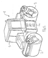
- FIG. 1 shows a road roller 1 in a perspective side view shown, which has a Doppelschemellenkung and this two individually steerable drum bandages 2, 3 comprises.
- the roller bandages are interconnected via a chassis 4, on which a driver's cab 5 is arranged for the roller guide.
- section V the road roller changes its drive direction in such a way that it now continues in reverse, including in section V the front roller drum 2, which after the change of direction the passive, in the direction of travel rear bandage, pivoted in zero position becomes, whereby shifted to the simplified representation arises above the representation of section V arranged section VI.
- roller bandage 3 is the active, so controlled bandage, causing the steering movements in Sections VII, VIII, VIIII and X.
- a control device 11 is provided, on the one hand, a steering input 12 in the form of a Lenkjoysticks or steering wheel and a steering mode input 13 and the other one Travel input 14 in the form of a switching joystick for entering the Direction of travel (forward / backward) and the driving gear connected are.
- control device 11 with two actual value pickups 15, 16 for detecting the steering angle of the bandages 2, 3, with associated Steering drives 17, 18 for the bandages and with a direction sensor 30 connected to detect the selected direction.
- the control device now works such that when in steering mode "Front steering" located steering mode input 12 pressing the Traveling joysticks 14 from the forward to the reverse direction or vice versa leads to that a corresponding signal to the Control device 11 is given, the change of direction first once two travel drives 19, 20, soften the two bandages 2, 3 control, feeds.
- the two steering drives 17, 18th controlled such that the steering drive after the change of direction in the direction of travel front roller drum active accordingly the steering requirements is controlled while the steering drive of the jewells Passive back bandage is driven only in such a way that the rear drum is transferred to its zero position.
- the present invention offers the advantage that the roller guide a facilitated, the ease of use increasing operation his road roller is provided, which automatically after the direction of travel has changed the steering mode to the new one
- the direction of travel adapts, in turn, the front in the direction of travel Roller drum for steering is controlled.
Landscapes
- Engineering & Computer Science (AREA)
- Architecture (AREA)
- Civil Engineering (AREA)
- Structural Engineering (AREA)
- Chemical & Material Sciences (AREA)
- Combustion & Propulsion (AREA)
- Transportation (AREA)
- Mechanical Engineering (AREA)
- Road Paving Machines (AREA)
Description
- Figur 1
- eine Straßenwalze in perspektivischer Seitenansicht;
- Figur 2
- eine schematische Darstellung der Arbeitsweise einer erfindungsgemäßen Straßenwalze; und
- Figur 3
- ein schematisches Schaltbild einer erfindungsgemäßen Straßenwalze.
Claims (14)
- Verfahren zur Steuerung des Lenk- und Fahrantriebes einer zweibandagigen Bodenverdichtungsvorrichtung mit Doppellenkung (1) insbesondere einer Straßenwalze mit Doppelschemellenkung, wobei der Lenkantrieb beider getrennt ansteuerbaren Walzenbandagen (2,3) von einer Steuerungsvorrichtung (11) in Abhängigkeit der vom Walzenführer ausgewählten Lenkvorgaben und/oder dem Lenkmodus gesteuert wird, wobei die Steuerungsvorrichtung den Lenkantrieb (17,18) beider Bandagen in einem auswählbaren Lenkmodus derart steuert, dass die jeweils in Fahrtrichtung vordere Bandage als aktive Bandage durch die Lenkvorgaben angesteuert wird,
dadurch gekennzeichnet, dass die Steuerungsvorrichtung bei oder nach einem Fahrtrichtungswechsel den Lenkantrieb beider Bandagen derart steuert, dass durch den Lenkantrieb die in Fahrtrichtung hintere Bandage als passive Bandage in ihre Nullstellung überführt wird. - Verfahren nach zumindest einem der vorstehenden Ansprüche,
dadurch gekennzeichnet, dass bei und/oder nach Eingabe des Fahrtrichtungswechsels die Steuerungsvorrichtung das Ansteuern der Lenkantriebe der Bandagen umschaltet. - Verfahren nach zumindest einem der vorstehenden Ansprüche,
dadurch gekennzeichnet, dass die Steuerungsvorrichtung das Umschalten der Bandagen sofort durchführt derart, dass beim Fahrtrichtungswechsel die vor dem Wechsel vordere, aktive Bandage nun als hintere, passive Bandage angesteuert und in die Nullstellung überführt wird, während die vor dem Wechsel hintere, passive in der Nullstellung befindliche Bandage danach als aktive, vordere Bandage entsprechend der jeweiligen Lenkvorgabe angesteuert wird. - Verfahren nach zumindest einem der vorstehenden Ansprüche,
dadurch gekennzeichnet, dass die Steuerungsvorrichtung das Umschalten der Bandagen derart sukzessive durchführt, dass die nach dem Fahrtrichtungswechsel hintere Bandage so lange als aktive Bandage angesteuert wird, bis sie einen voreingestellten Wert erreicht, woraufhin dann die Ansteuerung umgeschaltet wird und die hintere Bandage als passive und die vordere Bandage als aktive Bandage angesteuert wird und dass nach dem Fahrtrichtungswechsel bis zum Umschalten die vordere Bandage passiv ist und in ihrer Nullstellung verbleibt. - Verfahren nach Anspruch 4,
dadurch gekennzeichnet, dass der voreingestellte, das Umschalten der Bandagen auslösende Wert die Lenkstellung der in Fahrtrichtung nach dem Wiederanfahren hinteren Bandage ist, so dass bei Erreichen der Nullstellung die Ansteuerung umgeschaltet wird. - Verfahren nach Anspruch 4,
dadurch gekennzeichnet, dass der voreingestellte, das Umschalten der Bandagen auslösende Wert die Fahrtgeschwindigkeit der hinteren Bandage ist, so dass erst bei Erreichen einer vorgegebenen Geschwindigkeit die hintere Bandage in die Nullstellung überführt und die Ansteuerung der Bandagen umgeschaltet wird. - Verfahren nach zumindest einem der vorstehenden Ansprüche,
dadurch gekennzeichnet, dass die Überführung der nach dem Fahrtrichtungswechsel hinteren Bandage in die Nullstellung mit einer von deren Fahrtgeschwindigkeit abhängenden Geschwindigkeit erfolgt. - Verfahren nach zumindest einem der vorstehenden Ansprüche,
dadurch gekennzeichnet, dass ein voreingestellter Spurversatz bei der Umschaltung berücksichtigt wird derart, dass der Versatzwinkel der beiden Bandagen gegenüber der Walzenlängsachse zu einer Nullstellungsverschiebung führt, so dass die Nullstellung dann erreicht ist, wenn der Lenkwinkel der Bandage dem Versatzwinkel entspricht. - Verfahren nach zumindest einem der vorstehenden Ansprüche,
dadurch gekennzeichnet, dass der Steuerungsvorrichtung die jeweiligen Lenkwinkel der Walzenbandagen als Istwerte übermittelt werden, dass die Steuerungsvorrichtung das Ansteuern der Bandagen derart durchführt, dass die durch Lenkvorgaben vom Walzenführer eingegebenen Sollwerte den Istwerten gegenübergestellt werden, und dass die Lenkantriebe im Sinne eines Soll-Istwert-Abgleichs angesteuert werden. - Verfahren nach Anspruch 9,
dadurch gekennzeichnet, dass der der Nullstellung entsprechende Sollwert der passiven Bandage von der Steuerungsvorrichtung vorgegeben wird. - Zweibandagige Bodenverdichtungsvorrichtung mit Doppellenkung (1) insbesondere Straßenwalze mit Doppelschemellenkung, wobei die Bodenverdichtungsvorrichtung zwei getrennt durch eine Steuerungsvorrichtung in Abhängigkeit der vom Walzenführer ausgewählten Lenkvorgaben und/oder dem Lenkmodus über jeweils einen Lenkantrieb ansteuerbare Walzenbandagen aufweist, wobei die Steuerungsvorrichtung (11) derart steuerbar ist, dass sie in einem auswählbaren Lenkmodus die Lenkantriebe (17, 18) der beiden Bandagen (2, 3) in Abhängigkeit der Fahrtrichtung ansteuert, so dass der Lenkantrieb der jeweils in Fahrtrichtung vorderen Bandage zur Ausführung der Lenkvorgaben dient,
dadurch gekennzeichnet, dass an den Walzenbandagen (2, 3) Istwert-Aufnehmer (15, 16) zur Erfassung des Lenkwinkels der Bandagen vorgesehen sind, und dass die Steuerungsvorrichtung (11) an die Istwert-Aufnehmer angeschlossen ist, so dass die Steuerungsvorrichtung (11) bei oder nach einem Fahrtrichtungswechsel derart steuerbar ist, dass der Lenkantrieb (17, 18) der in Fahrtrichtung hinteren Bandage (2, 3) diese als passive Bandage in ihre Nullstellung überführt. - Bodenverdichtungsvorrichtung nach Anspruch 11,
dadurch gekennzeichnet, dass zur Eingabe der Lenkvorgaben als Sollwerte für die Steuerungsvorrichtung (11) zumindest eine Lenkeingabe (12) vorgesehen ist, und dass die Lenkeingabe an die Steuerungsvorrichtung angeschlossen ist. - Bodenverdichtungsvorrichtung nach zumindest den Ansprüchen 11 und 12,
dadurch gekennzeichnet, dass die Steuerungsvorrichtung (11) eine Steuereinheit für einen Soll-Istwert-Abgleich aufweist. - Bodenverdichtungsvorrichtung nach zumindest einem der Ansprüche 11 bis 12,
dadurch gekennzeichnet, dass die Steuerungsvorrichtung (11) mit einem Fahrtrichtungssensor (30) zur Erfassung der vom Walzenführer auswählbaren Fahrtrichtung verbunden ist.
Applications Claiming Priority (2)
| Application Number | Priority Date | Filing Date | Title |
|---|---|---|---|
| DE1998105038 DE19805038A1 (de) | 1998-02-09 | 1998-02-09 | Bodenverdichtungsvorrichtung und Verfahren zur Steuerung ihres Lenkantriebes |
| DE19805038 | 1998-02-09 |
Publications (4)
| Publication Number | Publication Date |
|---|---|
| EP0935023A2 EP0935023A2 (de) | 1999-08-11 |
| EP0935023A3 EP0935023A3 (de) | 2000-10-04 |
| EP0935023B1 true EP0935023B1 (de) | 2005-10-12 |
| EP0935023B2 EP0935023B2 (de) | 2017-05-10 |
Family
ID=7857045
Family Applications (1)
| Application Number | Title | Priority Date | Filing Date |
|---|---|---|---|
| EP99102125.4A Expired - Lifetime EP0935023B2 (de) | 1998-02-09 | 1999-02-03 | Bodenverdichtungsvorrichtung und Verfahren zur Steuerung ihres Lenkantriebes |
Country Status (2)
| Country | Link |
|---|---|
| EP (1) | EP0935023B2 (de) |
| DE (2) | DE19805038A1 (de) |
Families Citing this family (1)
| Publication number | Priority date | Publication date | Assignee | Title |
|---|---|---|---|---|
| DE10260902A1 (de) * | 2002-12-20 | 2004-07-15 | Hamm Ag | Selbstfahrendes Fahrzeug, insbesondere Straßenbaumaschine, sowie Verfahren zum Fahren und Lenken eines Fahrzeuges mit einem drehbaren Fahrersitz |
Family Cites Families (13)
| Publication number | Priority date | Publication date | Assignee | Title |
|---|---|---|---|---|
| US3279813A (en) † | 1964-11-16 | 1966-10-18 | C & M Ind Associates Inc | Selective four-wheel steering mechanism |
| CH552101A (it) * | 1972-12-19 | 1974-07-31 | Domenighetti Domenico | Macchina operatrice addensatrice multipla formata da tre o piu gruppi snodati fra loro per la compattazione del terreno. |
| US3868194A (en) † | 1974-02-06 | 1975-02-25 | Iowa Mfg Co | Expandable articulated tandem roller |
| US4043422A (en) * | 1976-11-19 | 1977-08-23 | Raygo, Inc. | Steering system for articulated vehicles |
| FR2434072A1 (fr) * | 1978-08-25 | 1980-03-21 | Albaret Sa | Dispositif pour la commande de direction et de vitesse d'un engin automobile |
| JPS585826B2 (ja) † | 1978-12-29 | 1983-02-01 | 本田技研工業株式会社 | 車輌の動力操舵装置 |
| US4412594A (en) † | 1980-08-27 | 1983-11-01 | Honda Giken Kogyo Kabushiki Kaisha | Steering system for motor vehicles |
| CA1287147C (en) * | 1985-10-24 | 1991-07-30 | Hiromu Fujimoto | Tractor equipped with working implements |
| JP2847303B2 (ja) † | 1989-10-17 | 1999-01-20 | 酒井重工業株式会社 | 転圧機械の操向装置 |
| DE4334742C2 (de) † | 1993-10-12 | 1997-04-30 | Francke Renate | Deaktivierbare Achslenkung |
| DE19536987A1 (de) * | 1995-03-31 | 1996-10-02 | Ammann Verdichtung Ag | Verfahren zur Lenkung einer zweibandagigen Bodenverdichtungsvorrichtung sowie Bodenverdichtungsvorrichtung |
| DE19607429B4 (de) † | 1996-02-28 | 2004-02-19 | Daimlerchrysler Ag | Fehlertolerante Steuerungseinrichtung für ein physikalisches System, insbesondere Fahrdynamikregeleinrichtung für ein Kraftfahrzeug |
| DE29620847U1 (de) * | 1996-11-30 | 1997-01-23 | Bomag GmbH, 56154 Boppard | Motorbetriebenes Bodenverdichtungsgerät |
-
1998
- 1998-02-09 DE DE1998105038 patent/DE19805038A1/de not_active Withdrawn
-
1999
- 1999-02-03 DE DE59912632T patent/DE59912632D1/de not_active Expired - Lifetime
- 1999-02-03 EP EP99102125.4A patent/EP0935023B2/de not_active Expired - Lifetime
Also Published As
| Publication number | Publication date |
|---|---|
| DE59912632D1 (de) | 2006-02-23 |
| EP0935023B2 (de) | 2017-05-10 |
| EP0935023A2 (de) | 1999-08-11 |
| EP0935023A3 (de) | 2000-10-04 |
| DE19805038A1 (de) | 1999-08-12 |
Similar Documents
| Publication | Publication Date | Title |
|---|---|---|
| DE10030449B4 (de) | Automatisches Lenkungssystem für ein Fahrzeug | |
| DE69730570T2 (de) | Automatisches Lenksystem für ein Fahrzeug | |
| DE3831932C2 (de) | Kraftfahrzeug | |
| EP2899318B1 (de) | Selbstfahrende Straßenbaumaschine, insbesondere Straßenwalze, sowie Verfahren zum Fahren einer Straßenbaumaschine | |
| DE19922284B4 (de) | Automatische Lenkvorrichtung für ein Fahrzeug | |
| DE102019002442A1 (de) | Verfahren zur teilautonomen Steuerung einer Baumaschine, insbesondere einer Bodenverdichtungsmaschine und Baumaschine, insbesondere Bodenverdichtungsmaschine | |
| DE102005023286A1 (de) | Verfahren und Vorrichtung zur Lenkungseinstellung und Lenkung von Rädern eines Fahrzeuges mit Achsschenkellenkung | |
| DE3538802C2 (de) | Automatisches Differential-Sperrsystem für Arbeitsfahrzeuge sowie mit einem automatischen Differential-Sperrsystem ausgestattetes Arbeitsfahrzeug | |
| DE3635120A1 (de) | Zugmaschine mit arbeitsgeraeten | |
| CH619897A5 (de) | ||
| DE102009000452B4 (de) | Arbeitsfahrzeug | |
| EP0988477B1 (de) | Verfahren und einrichtung zur lastschaltbaren umschaltung eines hydrostatischen fahrantriebes einer mobilen baumaschine | |
| EP2878858B1 (de) | Bedienkonzept zum Fahren eines Selbstfahrers | |
| EP3487804B1 (de) | Flurförderzeug | |
| DE3928670A1 (de) | Geschwindigkeitsregeleinrichtung fuer fahrzeuge | |
| EP2935087A1 (de) | Lenkverfahren und flurförderzeug | |
| EP0545054B1 (de) | Nicht spurgebundenes Fahrzeug mit willkürlich lenkbaren Vorderrädern und selbsttätig arbeitender Hinterradzusatzlenkung | |
| EP0935023B2 (de) | Bodenverdichtungsvorrichtung und Verfahren zur Steuerung ihres Lenkantriebes | |
| DE102016009646A1 (de) | Bodenfräse und Verfahren zum Betrieb einer Bodenfräse | |
| DE102006035080A1 (de) | Eigenantriebs-Schneeräummaschine | |
| EP0935024B1 (de) | Bodenverdichtungsvorrichtung und Verfahren zu deren Steuerung | |
| EP0935025B2 (de) | Bodenverdichtungsvorrichtung und Verfahren zur Steuerung des Fahrantriebes einer Bodenverdichtungsvorrichtung | |
| EP1879768B1 (de) | Verfahren zum aktivieren eines rangiermodus eines kraftfahrzeuges | |
| DE19838773C1 (de) | Bremseinrichtung für eine Arbeitsmaschine | |
| EP2537403B1 (de) | Handgeführte selbstfahrende Antriebsmaschine |
Legal Events
| Date | Code | Title | Description |
|---|---|---|---|
| PUAI | Public reference made under article 153(3) epc to a published international application that has entered the european phase |
Free format text: ORIGINAL CODE: 0009012 |
|
| AK | Designated contracting states |
Kind code of ref document: A2 Designated state(s): BE CH DE DK FR LI NL SE |
|
| AX | Request for extension of the european patent |
Free format text: AL;LT;LV;MK;RO;SI |
|
| PUAL | Search report despatched |
Free format text: ORIGINAL CODE: 0009013 |
|
| AK | Designated contracting states |
Kind code of ref document: A3 Designated state(s): AT BE CH CY DE DK ES FI FR GB GR IE IT LI LU MC NL PT SE |
|
| AX | Request for extension of the european patent |
Free format text: AL;LT;LV;MK;RO;SI |
|
| 17P | Request for examination filed |
Effective date: 20001213 |
|
| AKX | Designation fees paid |
Free format text: BE CH DE DK FR LI NL SE |
|
| 17Q | First examination report despatched |
Effective date: 20030319 |
|
| RAP1 | Party data changed (applicant data changed or rights of an application transferred) |
Owner name: BOMAG GMBH |
|
| GRAP | Despatch of communication of intention to grant a patent |
Free format text: ORIGINAL CODE: EPIDOSNIGR1 |
|
| GRAS | Grant fee paid |
Free format text: ORIGINAL CODE: EPIDOSNIGR3 |
|
| GRAA | (expected) grant |
Free format text: ORIGINAL CODE: 0009210 |
|
| AK | Designated contracting states |
Kind code of ref document: B1 Designated state(s): BE CH DE DK FR LI NL SE |
|
| PG25 | Lapsed in a contracting state [announced via postgrant information from national office to epo] |
Ref country code: NL Free format text: LAPSE BECAUSE OF FAILURE TO SUBMIT A TRANSLATION OF THE DESCRIPTION OR TO PAY THE FEE WITHIN THE PRESCRIBED TIME-LIMIT Effective date: 20051012 |
|
| REG | Reference to a national code |
Ref country code: CH Ref legal event code: NV Representative=s name: ROTTMANN, ZIMMERMANN + PARTNER AG Ref country code: CH Ref legal event code: EP |
|
| REG | Reference to a national code |
Ref country code: SE Ref legal event code: TRGR |
|
| PG25 | Lapsed in a contracting state [announced via postgrant information from national office to epo] |
Ref country code: DK Free format text: LAPSE BECAUSE OF FAILURE TO SUBMIT A TRANSLATION OF THE DESCRIPTION OR TO PAY THE FEE WITHIN THE PRESCRIBED TIME-LIMIT Effective date: 20060112 |
|
| REF | Corresponds to: |
Ref document number: 59912632 Country of ref document: DE Date of ref document: 20060223 Kind code of ref document: P |
|
| PG25 | Lapsed in a contracting state [announced via postgrant information from national office to epo] |
Ref country code: BE Free format text: LAPSE BECAUSE OF NON-PAYMENT OF DUE FEES Effective date: 20060228 |
|
| NLV1 | Nl: lapsed or annulled due to failure to fulfill the requirements of art. 29p and 29m of the patents act | ||
| ET | Fr: translation filed | ||
| PLBI | Opposition filed |
Free format text: ORIGINAL CODE: 0009260 |
|
| PLAX | Notice of opposition and request to file observation + time limit sent |
Free format text: ORIGINAL CODE: EPIDOSNOBS2 |
|
| 26 | Opposition filed |
Opponent name: ABG ALLGEMEINE BAUMASCHINEN-GESELLSCHAFT MBH Effective date: 20060712 |
|
| PLAF | Information modified related to communication of a notice of opposition and request to file observations + time limit |
Free format text: ORIGINAL CODE: EPIDOSCOBS2 |
|
| PLBB | Reply of patent proprietor to notice(s) of opposition received |
Free format text: ORIGINAL CODE: EPIDOSNOBS3 |
|
| BERE | Be: lapsed |
Owner name: BOMAG G.M.B.H. Effective date: 20060228 |
|
| REG | Reference to a national code |
Ref country code: CH Ref legal event code: PFA Owner name: BOMAG GMBH Free format text: BOMAG GMBH#HELLERWALD#56154 BOPPARD (DE) -TRANSFER TO- BOMAG GMBH#HELLERWALD#56154 BOPPARD (DE) |
|
| PGFP | Annual fee paid to national office [announced via postgrant information from national office to epo] |
Ref country code: SE Payment date: 20120228 Year of fee payment: 14 |
|
| PGFP | Annual fee paid to national office [announced via postgrant information from national office to epo] |
Ref country code: CH Payment date: 20130308 Year of fee payment: 15 |
|
| REG | Reference to a national code |
Ref country code: SE Ref legal event code: EUG |
|
| PG25 | Lapsed in a contracting state [announced via postgrant information from national office to epo] |
Ref country code: SE Free format text: LAPSE BECAUSE OF NON-PAYMENT OF DUE FEES Effective date: 20130204 |
|
| APBM | Appeal reference recorded |
Free format text: ORIGINAL CODE: EPIDOSNREFNO |
|
| APBP | Date of receipt of notice of appeal recorded |
Free format text: ORIGINAL CODE: EPIDOSNNOA2O |
|
| APAH | Appeal reference modified |
Free format text: ORIGINAL CODE: EPIDOSCREFNO |
|
| REG | Reference to a national code |
Ref country code: CH Ref legal event code: PL |
|
| PG25 | Lapsed in a contracting state [announced via postgrant information from national office to epo] |
Ref country code: LI Free format text: LAPSE BECAUSE OF NON-PAYMENT OF DUE FEES Effective date: 20140228 Ref country code: CH Free format text: LAPSE BECAUSE OF NON-PAYMENT OF DUE FEES Effective date: 20140228 |
|
| REG | Reference to a national code |
Ref country code: FR Ref legal event code: PLFP Year of fee payment: 17 |
|
| PGFP | Annual fee paid to national office [announced via postgrant information from national office to epo] |
Ref country code: FR Payment date: 20150217 Year of fee payment: 17 |
|
| APBU | Appeal procedure closed |
Free format text: ORIGINAL CODE: EPIDOSNNOA9O |
|
| REG | Reference to a national code |
Ref country code: FR Ref legal event code: ST Effective date: 20161028 |
|
| PG25 | Lapsed in a contracting state [announced via postgrant information from national office to epo] |
Ref country code: FR Free format text: LAPSE BECAUSE OF NON-PAYMENT OF DUE FEES Effective date: 20160229 |
|
| PUAH | Patent maintained in amended form |
Free format text: ORIGINAL CODE: 0009272 |
|
| STAA | Information on the status of an ep patent application or granted ep patent |
Free format text: STATUS: PATENT MAINTAINED AS AMENDED |
|
| 27A | Patent maintained in amended form |
Effective date: 20170510 |
|
| AK | Designated contracting states |
Kind code of ref document: B2 Designated state(s): BE CH DE DK FR LI NL SE |
|
| REG | Reference to a national code |
Ref country code: DE Ref legal event code: R102 Ref document number: 59912632 Country of ref document: DE |
|
| PGFP | Annual fee paid to national office [announced via postgrant information from national office to epo] |
Ref country code: DE Payment date: 20180216 Year of fee payment: 20 |
|
| REG | Reference to a national code |
Ref country code: DE Ref legal event code: R071 Ref document number: 59912632 Country of ref document: DE |