EP0933562A2 - System zur Eingriffssteuerung, vorwärts und rückwärts, eines automatischen Mehrganggetriebes - Google Patents
System zur Eingriffssteuerung, vorwärts und rückwärts, eines automatischen Mehrganggetriebes Download PDFInfo
- Publication number
- EP0933562A2 EP0933562A2 EP99300601A EP99300601A EP0933562A2 EP 0933562 A2 EP0933562 A2 EP 0933562A2 EP 99300601 A EP99300601 A EP 99300601A EP 99300601 A EP99300601 A EP 99300601A EP 0933562 A2 EP0933562 A2 EP 0933562A2
- Authority
- EP
- European Patent Office
- Prior art keywords
- pressure
- clutch
- valve means
- engagement
- solenoid
- Prior art date
- Legal status (The legal status is an assumption and is not a legal conclusion. Google has not performed a legal analysis and makes no representation as to the accuracy of the status listed.)
- Granted
Links
- 230000002441 reversible effect Effects 0.000 title claims abstract description 140
- 230000005540 biological transmission Effects 0.000 title claims abstract description 34
- 230000003068 static effect Effects 0.000 title description 5
- 230000007935 neutral effect Effects 0.000 claims abstract description 22
- 239000012530 fluid Substances 0.000 claims description 9
- 230000000694 effects Effects 0.000 claims description 5
- 230000001970 hydrokinetic effect Effects 0.000 claims description 4
- 230000001105 regulatory effect Effects 0.000 claims 4
- 230000001276 controlling effect Effects 0.000 claims 2
- 238000006243 chemical reaction Methods 0.000 abstract description 9
- 230000006870 function Effects 0.000 description 20
- 230000008878 coupling Effects 0.000 description 10
- 238000010168 coupling process Methods 0.000 description 10
- 238000005859 coupling reaction Methods 0.000 description 10
- 238000011217 control strategy Methods 0.000 description 5
- 230000001965 increasing effect Effects 0.000 description 5
- 239000000446 fuel Substances 0.000 description 4
- 230000001360 synchronised effect Effects 0.000 description 3
- 238000010586 diagram Methods 0.000 description 2
- 230000001133 acceleration Effects 0.000 description 1
- 230000009471 action Effects 0.000 description 1
- 230000003321 amplification Effects 0.000 description 1
- 238000004873 anchoring Methods 0.000 description 1
- 230000008859 change Effects 0.000 description 1
- 238000002485 combustion reaction Methods 0.000 description 1
- 238000010276 construction Methods 0.000 description 1
- 238000012217 deletion Methods 0.000 description 1
- 230000037430 deletion Effects 0.000 description 1
- 230000009977 dual effect Effects 0.000 description 1
- 230000002708 enhancing effect Effects 0.000 description 1
- 238000003199 nucleic acid amplification method Methods 0.000 description 1
- 230000004044 response Effects 0.000 description 1
- 230000007704 transition Effects 0.000 description 1
Images




Classifications
-
- F—MECHANICAL ENGINEERING; LIGHTING; HEATING; WEAPONS; BLASTING
- F16—ENGINEERING ELEMENTS AND UNITS; GENERAL MEASURES FOR PRODUCING AND MAINTAINING EFFECTIVE FUNCTIONING OF MACHINES OR INSTALLATIONS; THERMAL INSULATION IN GENERAL
- F16H—GEARING
- F16H61/00—Control functions within control units of change-speed- or reversing-gearings for conveying rotary motion ; Control of exclusively fluid gearing, friction gearing, gearings with endless flexible members or other particular types of gearing
- F16H61/02—Control functions within control units of change-speed- or reversing-gearings for conveying rotary motion ; Control of exclusively fluid gearing, friction gearing, gearings with endless flexible members or other particular types of gearing characterised by the signals used
- F16H61/0202—Control functions within control units of change-speed- or reversing-gearings for conveying rotary motion ; Control of exclusively fluid gearing, friction gearing, gearings with endless flexible members or other particular types of gearing characterised by the signals used the signals being electric
- F16H61/0204—Control functions within control units of change-speed- or reversing-gearings for conveying rotary motion ; Control of exclusively fluid gearing, friction gearing, gearings with endless flexible members or other particular types of gearing characterised by the signals used the signals being electric for gearshift control, e.g. control functions for performing shifting or generation of shift signal
- F16H61/0246—Control functions within control units of change-speed- or reversing-gearings for conveying rotary motion ; Control of exclusively fluid gearing, friction gearing, gearings with endless flexible members or other particular types of gearing characterised by the signals used the signals being electric for gearshift control, e.g. control functions for performing shifting or generation of shift signal characterised by initiating reverse gearshift
-
- F—MECHANICAL ENGINEERING; LIGHTING; HEATING; WEAPONS; BLASTING
- F16—ENGINEERING ELEMENTS AND UNITS; GENERAL MEASURES FOR PRODUCING AND MAINTAINING EFFECTIVE FUNCTIONING OF MACHINES OR INSTALLATIONS; THERMAL INSULATION IN GENERAL
- F16H—GEARING
- F16H61/00—Control functions within control units of change-speed- or reversing-gearings for conveying rotary motion ; Control of exclusively fluid gearing, friction gearing, gearings with endless flexible members or other particular types of gearing
- F16H61/04—Smoothing ratio shift
- F16H2061/0485—Smoothing ratio shift during range shift from neutral (N) to reverse (R)
-
- F—MECHANICAL ENGINEERING; LIGHTING; HEATING; WEAPONS; BLASTING
- F16—ENGINEERING ELEMENTS AND UNITS; GENERAL MEASURES FOR PRODUCING AND MAINTAINING EFFECTIVE FUNCTIONING OF MACHINES OR INSTALLATIONS; THERMAL INSULATION IN GENERAL
- F16H—GEARING
- F16H61/00—Control functions within control units of change-speed- or reversing-gearings for conveying rotary motion ; Control of exclusively fluid gearing, friction gearing, gearings with endless flexible members or other particular types of gearing
- F16H61/04—Smoothing ratio shift
- F16H2061/0488—Smoothing ratio shift during range shift from neutral (N) to drive (D)
-
- F—MECHANICAL ENGINEERING; LIGHTING; HEATING; WEAPONS; BLASTING
- F16—ENGINEERING ELEMENTS AND UNITS; GENERAL MEASURES FOR PRODUCING AND MAINTAINING EFFECTIVE FUNCTIONING OF MACHINES OR INSTALLATIONS; THERMAL INSULATION IN GENERAL
- F16H—GEARING
- F16H61/00—Control functions within control units of change-speed- or reversing-gearings for conveying rotary motion ; Control of exclusively fluid gearing, friction gearing, gearings with endless flexible members or other particular types of gearing
- F16H61/20—Preventing gear creeping ; Transmission control during standstill, e.g. hill hold control
- F16H2061/207—Preventing gear creeping ; Transmission control during standstill, e.g. hill hold control by neutral control
-
- F—MECHANICAL ENGINEERING; LIGHTING; HEATING; WEAPONS; BLASTING
- F16—ENGINEERING ELEMENTS AND UNITS; GENERAL MEASURES FOR PRODUCING AND MAINTAINING EFFECTIVE FUNCTIONING OF MACHINES OR INSTALLATIONS; THERMAL INSULATION IN GENERAL
- F16H—GEARING
- F16H2312/00—Driving activities
- F16H2312/02—Driving off
-
- F—MECHANICAL ENGINEERING; LIGHTING; HEATING; WEAPONS; BLASTING
- F16—ENGINEERING ELEMENTS AND UNITS; GENERAL MEASURES FOR PRODUCING AND MAINTAINING EFFECTIVE FUNCTIONING OF MACHINES OR INSTALLATIONS; THERMAL INSULATION IN GENERAL
- F16H—GEARING
- F16H61/00—Control functions within control units of change-speed- or reversing-gearings for conveying rotary motion ; Control of exclusively fluid gearing, friction gearing, gearings with endless flexible members or other particular types of gearing
- F16H61/02—Control functions within control units of change-speed- or reversing-gearings for conveying rotary motion ; Control of exclusively fluid gearing, friction gearing, gearings with endless flexible members or other particular types of gearing characterised by the signals used
- F16H61/0202—Control functions within control units of change-speed- or reversing-gearings for conveying rotary motion ; Control of exclusively fluid gearing, friction gearing, gearings with endless flexible members or other particular types of gearing characterised by the signals used the signals being electric
- F16H61/0204—Control functions within control units of change-speed- or reversing-gearings for conveying rotary motion ; Control of exclusively fluid gearing, friction gearing, gearings with endless flexible members or other particular types of gearing characterised by the signals used the signals being electric for gearshift control, e.g. control functions for performing shifting or generation of shift signal
- F16H61/0206—Layout of electro-hydraulic control circuits, e.g. arrangement of valves
-
- F—MECHANICAL ENGINEERING; LIGHTING; HEATING; WEAPONS; BLASTING
- F16—ENGINEERING ELEMENTS AND UNITS; GENERAL MEASURES FOR PRODUCING AND MAINTAINING EFFECTIVE FUNCTIONING OF MACHINES OR INSTALLATIONS; THERMAL INSULATION IN GENERAL
- F16H—GEARING
- F16H61/00—Control functions within control units of change-speed- or reversing-gearings for conveying rotary motion ; Control of exclusively fluid gearing, friction gearing, gearings with endless flexible members or other particular types of gearing
- F16H61/04—Smoothing ratio shift
- F16H61/06—Smoothing ratio shift by controlling rate of change of fluid pressure
- F16H61/061—Smoothing ratio shift by controlling rate of change of fluid pressure using electric control means
-
- F—MECHANICAL ENGINEERING; LIGHTING; HEATING; WEAPONS; BLASTING
- F16—ENGINEERING ELEMENTS AND UNITS; GENERAL MEASURES FOR PRODUCING AND MAINTAINING EFFECTIVE FUNCTIONING OF MACHINES OR INSTALLATIONS; THERMAL INSULATION IN GENERAL
- F16H—GEARING
- F16H61/00—Control functions within control units of change-speed- or reversing-gearings for conveying rotary motion ; Control of exclusively fluid gearing, friction gearing, gearings with endless flexible members or other particular types of gearing
- F16H61/20—Preventing gear creeping ; Transmission control during standstill, e.g. hill hold control
-
- F—MECHANICAL ENGINEERING; LIGHTING; HEATING; WEAPONS; BLASTING
- F16—ENGINEERING ELEMENTS AND UNITS; GENERAL MEASURES FOR PRODUCING AND MAINTAINING EFFECTIVE FUNCTIONING OF MACHINES OR INSTALLATIONS; THERMAL INSULATION IN GENERAL
- F16H—GEARING
- F16H61/00—Control functions within control units of change-speed- or reversing-gearings for conveying rotary motion ; Control of exclusively fluid gearing, friction gearing, gearings with endless flexible members or other particular types of gearing
- F16H61/68—Control functions within control units of change-speed- or reversing-gearings for conveying rotary motion ; Control of exclusively fluid gearing, friction gearing, gearings with endless flexible members or other particular types of gearing specially adapted for stepped gearings
- F16H61/684—Control functions within control units of change-speed- or reversing-gearings for conveying rotary motion ; Control of exclusively fluid gearing, friction gearing, gearings with endless flexible members or other particular types of gearing specially adapted for stepped gearings without interruption of drive
- F16H61/686—Control functions within control units of change-speed- or reversing-gearings for conveying rotary motion ; Control of exclusively fluid gearing, friction gearing, gearings with endless flexible members or other particular types of gearing specially adapted for stepped gearings without interruption of drive with orbital gears
Definitions
- the invention relates to an automatic transmission having pressure-operated clutches and brake servos for establishing and disestablishing torque flow paths for forward drive torque delivery and for reverse drive torque delivery.
- the engagement control system of the present invention has features that are common to the engagement control system of the automatic transmission shown in U.S. Patent No. 5,612,874, which is assigned to the assignee of the present invention.
- the transmission of the ⁇ 874 patent discloses a planetary transmission having a so-called three-speed Simpson gear set and a simple planetary gear set arranged in series. The two gear sets together establish four forward driving ratios and a single reverse ratio. Pressure-operated clutches and brakes establish each of the forward driving ratios and the reverse ratio as they are applied and released under the control of an electronic processor and hydraulic control valve circuit control system.
- a hydrokinetic torque converter is disposed between the crankshaft of an internal combustion engine and torque input elements of the transmission.
- a neutral state is achieved by disengaging a forward drive clutch, thus interrupting the torque flow path between the planetary gearing and the turbine of the torque converter.
- the engagement control system disclosed in the ⁇ 874 patent uses one variable force solenoid and one on/off solenoid for controlling both forward and reverse engagements.
- the variable force solenoid communicates with a modulator valve for forward engagements and with a separate modulator valve for reverse engagements. Both of these modulator valves modulate line pressure developed by a main regulator valve in the control valve circuit for producing a clutch pressure that starts from zero pressure to a maximum value, thereby allowing a cushioned engagement of the forward and reverse engagements.
- the forward clutch of the design of the ⁇ 874 patent which establishes a driving connection between the turbine and the input element of the gearing, is controlled.
- a separate high speed ratio clutch is controlled simultaneously with the engagement of a separate reverse brake.
- Separate engagement control valves are used to distribute either line pressure or clutch pressure to the high clutch or to the forward clutch. This is required in order to satisfy the stall torque capacity that is required during forward and reverse accelerations of the vehicle from a standing start.
- the reverse engagement control valve of the design of the ⁇ 874 patent distributes either reverse line pressure or a reverse modulator pressure to the high clutch during reverse engagement depending upon the output pressure of the on/off solenoid and the variable force solenoid pressure. Thus, there is one pressure threshold for changing between the reverse modulator pressure and the line pressure in reverse drive.
- the forward engagement control valve distributes forward clutch pressure or full line pressure, depending upon the mode of operation of the variable force solenoid for controlling forward clutch pressure.
- An engagement control valve switches the forward clutch pressure to full line pressure after completion of the forward engagement. This is required since the forward modulator valve must be used, following forward engagement, for controlling upshifts and downshifts between gear ratios. Re-application of forward modulator pressure can be achieved only by moving the manual valve under the control of the operator to a neutral position and then re-engaging the forward clutch.
- the improved engagement control system of the present invention includes three variable force solenoids rather than one. Two of them are used for the purpose of amplifying line pressure. One variable force solenoid is dedicated for controlling reverse engagements and a separate variable force solenoid is dedicated for forward engagement control.
- the variable force solenoids communicate with pressure modulator valves, which have a multiplexing function to establish variable thresholds for engagement control for reverse drive and engagement control for forward drive by establishing maximum stall capacity and modified engagement control pressures.
- multiplexing is used to describe the establishment of two functionally independent control pressures for the clutches and brakes distributed by a single pressure control valve, which in this case are the outputs of the pressure modulator valves to the clutches and brakes for reverse engagement and for forward engagement.
- Alternate versions for reverse engagement control and for forward engagement control are provided depending upon whether the gearing is characterised by an overrunning coupling for establishing a torque reaction point for the Simpson gear set or whether the reaction point for the Simpson gear set is established by a pressure-operated friction brake.
- the electronically controlled clutch engagement feature of the present invention is capable of achieving smooth static engagements with high engine torques and high engine speeds even though the line pressure is high. An uncomfortable and harsh engagement is avoided because of the use of three variable force solenoids rather than only one variable force solenoid and one on/off solenoid for controlling all engagements in reverse drive and forward drive.
- the neutral idle feature of the invention reduces load on the engine under some operating modes regardless of whether the vehicle is standing still or is moving.
- the engine throttle in either event, is closed and the engine operates at idle speed.
- the reduced engine load during the neutral idle state requires partial engagement of the forward clutch.
- a minimal slip across the forward clutch is controlled based on the vehicle operating mode.
- the idle speed control system for the engine then can set the air/fuel ratio at a leaner setting, which results in improved engine fuel economy.
- the neutral idle feature should be available in each gear ratio, which requires the neutral idle strategy to be independent of the states of the stages of the solenoids in the shift control valve system.
- the control valve system of the invention is able to provide small, incremental clutch pressure adjustments to effect neutral idle, but it is capable also of responding to sudden throttle position changes.
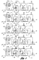
- FIG. 1 several operating modes for a first embodiment of a transmission gearing arrangement is illustrated schematically.
- the transmission includes a so-called Simpson gear set, shown generally at 10, and a simple planetary gear set, shown generally at 12.
- a torque input ring gear 14 for the Simpson gear set receives torque from a forward drive clutch C3, which is engaged during each of five forward driving ratios.
- Overrunning coupling 16 between the carrier and ring gear of gear set 12 is engaged during operation in the first, third and fourth ratios when sun gear brake B1 is released.
- the sun gear 18 for the Simpson gear set is adapted to be braked during third speed ratio operation by brake band B2.
- Clutch C3 delivers torque to ring gear 14 through overrunning coupling 16 during operation in the first, third and fourth forward driving ratios.
- a carrier of the first gear unit of the Simpson gear set delivers torque to the torque output shaft 20.
- the torque on the sun gear 18 is multiplied by the second gear unit of the Simpson gear set as a second torque flow path is established extending to the torque output shaft 20.
- Turbine shaft 22 acts as a torque input shaft for the gear unit 10.
- the engine crankshaft 24 is connected drivably to impeller 26 of the hydrokinetic torque converter.
- the turbine 28 of the hydrokinetic torque converter is connected to the turbine shaft 22.
- brake band B1 anchors the sun gear of the simple planetary gear set 12.
- Turbine torque in shaft 22 then drives the ring gear of the simple planetary gear set 12 with an overdrive ratio as the sun gear of the simple planetary gear set acts as a reaction point.
- the output torque of the simple planetary gear set then is distributed through engaged clutch C3 to the Simpson planetary gear set.
- Third speed ratio is achieved by engaging brake B2, which anchors the sun gear of the Simpson planetary gear set.
- the overrunning coupling of the simple planetary gear set then drives the input ring gear 14 of the Simpson gear set at turbine shaft speed.
- the second gear unit of the Simpson gear set does not deliver torque as it does in the case of operation in the first and second ratios, where overrunning coupling OWC2 anchors the carrier of the second gear unit of the Simpson gear set.
- the fourth ratio is a direct drive ratio. It is achieved by engaging simultaneously clutch C2 and clutch C3. All of the brakes are released.
- the ratio change from the third ratio to the fourth ratio, from the fourth ratio to the third ratio, and from the fifth ratio to the third ratio involves a synchronous shift that is accomplished by engaging clutch C2 and releasing brake B2, or by releasing brake B1 and clutch C3 while applying brake B2 in the case of fifth ratio operation.
- Reverse ratio is achieved by applying clutch C2 and anchoring the carrier of the second gear unit of the Simpson gear set by applying brake B3.
- Clutch C2 is applied, so turbine shaft torque is distributed through gear set 12 to the sun gear 18. With the rear carrier anchored, the output shaft 20 and the ring gear for the second gear unit of the Simpson gear set are driven in a reverse direction.
- Figure 2 shows schematically a transmission similar to the transmission illustrated in Figure 1 except that the 4-3/3-4 and 5-3 shifts are non-synchronous. That is, the sun gear of the Simpson planetary gear set is anchored by an overrunning coupling shown at C4. The outer race of the overrunning coupling is braked against the transmission case by a pressure-operated friction coupling C4.
- the elements of the transmission illustrated in Figure 2 that have corresponding elements in the transmission of Figure 1 have been designated by similar reference numerals, although prime notations are added to the elements of Figure 2.
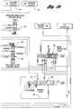
- the overall reverse and forward engagement control valve system is shown in Figures 3a and 3b.
- This control system includes three variable force solenoid valves shown at 30, 32 and 34 in Figure 3a.
- the so-called multiplexing functions of these variable force solenoid valves for static reverse engagement and for static forward engagement now will be described.
- a line pressure pump 36 supplies fluid pressure to main regulator valve 38 through line pressure passage 40.
- the main regulator valve is shown in Figure 3b and the pump is shown in Figure 3a.
- Reverse drive for the transmission shown in Figure 1, as well as in the transmission shown in Figure 2, is achieved by applying brake B3 which anchors the carrier of the second gear unit of the Simpson gear set. Clutch C3 is released and clutch C2 is applied, as mentioned previously. Thus, turbine torque is delivered through clutch C2 directly to the sun gear 18 of the Simpson gear set. With the carrier being anchored by the brake band B3, the ring gear of the second gear unit of the Simpson gear set and the output shaft 20 are driven in a reverse direction.
- the clutch C2 is controlled rather than the brake B3, because the brake B3 has a higher capacity gain compared to the capacity gain of the clutch C2. In contrast, during forward engagements, the forward clutch C3 is controlled.
- the rear brake band B3 is applied with line pressure first. That engagement is followed by engagement of the high clutch C2.
- the high clutch capacity then is controlled independently following rear brake engagement.
- Figure 3a shows a single on/off solenoid at 41, which is part of the shift solenoid valve system.
- a high clutch control valve 42 communicates with the high clutch apply pressure chamber for the clutch C2, as shown at 44 in Figure 3b.
- the engagement control valve for reverse is shown at 46 in Figure 3a. It establishes an input pressure for the high clutch control valve 42.
- An engagement control valve for forward is shown at 48. It provides a feed pressure in passage 50 for the forward clutch C3, as shown at 52.
- the input pressures for the engagement control valve for forward, seen at 48, is supplied by a variable force solenoid modulator control valve 54 and a variable force solenoid modulator valve 56.
- the circuit of Figures 3a and 3b includes also a variable force solenoid CR/R shuttle valve at 58, which distributes either variable force solenoid pressure from solenoid valve 34 to the high clutch apply circuit or modulated CR pressure from pressure modulator reverse valve 60 (or reverse line pressure) to the high clutch apply circuit.
- variable force solenoid valves and the on/off solenoids of the shift valve system are controlled by a microprocessor with sensor input portions that receive engine and transmission operating variables and a memory portion that stores control strategy and control algorithms.
- the three variable force solenoids 30, 32 and 34 are proportional control devices that convert current with an average of 0 to 1 amp into a pressure of 8 to 0 bar.
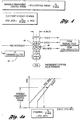
- the transfer function for this conversion which is stored in the ROM memory of the electronic processor, is shown in Figure 9, where line pressure and modulator pressure are plotted against the output of the variable force solenoids VFS1, VFS2 or VFS3.
- the maximum pressure output of these valves is 8 bar, as shown in Figure 9, as the amperage at the solenoids of the solenoid valves is varied.
- the output pressure for the variable force solenoid 34 and the output pressure for variable force solenoid 32 (VFS2/MOD), which will be described with reference to Figure 10, also are illustrated in Figure 9 as variables plotted against the output pressures of the variable force solenoids.
- the transfer function shown in Figure 9 is an electronic-hydraulic transfer function used to adjust the capacity of the clutches involved in either a forward engagement or a reverse engagement.
- the solenoids 30 and 32 communicate with a main regulator valve assembly 38.
- the main regulator valve assembly output pressure is amplified as the variable force solenoid pressures are applied to the boost valve portion of the main regulator valve assembly 38.
- the feed pressure for each of the variable force solenoid valves 30 and 32 is line pressure.
- variable force solenoid 30 communicates with the variable force solenoid modulator control valve 56 and the variable force solenoid modulator valve 54.
- the pressure developed by the variable force solenoid 30 is a pressure called VFS1/MOD in Figure 3b, which is useful in developing a smooth engagement of the forward clutch 52.
- Variable force solenoid 34 is connected to the reverse pressure modulator valve 60. This is required in order to provide adequate control for the high clutch during a reverse engagement. In this instance, the characteristic of the clutch pressure modulator valve for reverse drive produces a smooth reverse engagement just as the valve 56 provides smooth forward clutch engagement.
- Variable force solenoid pressure VFS3 is used also, together with pressure VFS2, to control the pressure thresholds where CR pressure satisfies capacity for smooth engagement control and R pressure satisfies the stall capacity.
- the pressure VFS2 is used to vary the engagement control range for the reverse and forward engagements, depending upon the operating range of the vehicle. This is referred to as the pressure threshold where the engagement pressure is multiplexed with stall pressure for forward engagements or reverse engagements.
- Figures 6a and 6b show a modified control valve system for forward engagement and for reverse engagement. It is applicable only to the transmission illustrated schematically in Figure 1.
- the control valve system of Figures 6a and 6b has elements that are common to the control valve system of Figures 3a and 3b. Corresponding numerals are used to designate the various elements of the control valve system of Figures 6a and 6b, although prime notations are added.
- variable force solenoids VFS1 and VFS3 shown at 30' and 34' in Figure 6a for forward and reverse engagements are the same as the corresponding valves for the control valve system of Figures 3a and 3b except that the forward engagement control system of the circuit of Figures 6a and 6b contains the additional capability of a "neutral idle" function.
- This feature is shown in greater detail in the enlarged view of the engagement control valve for forward drive seen in Figure 8. This allows multiplexing of the VFS1/MOD pressure and the line pressure for the forward clutch under all operating modes depending upon the amount of pressure applied by VFS2 and VFS3.
- a forward engagement control system is shown in Figures 3a and 3b.
- the forward engagement control system consists of the VFS1/MOD valve shown at 56 in Figure 3b and the forward engagement control valve shown at 48 in Figure 3a.
- the forward engagement control valve is shown in enlarged form in Figure 4.
- VFS1/MOD valve 56 When the driver moves the manual lever to adjust the manual valve 66, from the neutral position or the reverse position to the drive position, or to the M3, M2 or M1 positions, a forward engagement is initiated. At this point, line pressure is distributed by the manual valve 66 through the passage 68. This acts as an input pressure for the VFS1/MOD valve 56.
- the characteristic of the VFS1/MOD valve is shown in Figure 10.
- the VFS1/MOD valve 56 is controlled by the VFS1 pressure signal developed by the variable force solenoid 30.
- the VFS1 pressure signal is in equilibrium with the VFS1/MOD pressure and the spring force derived from the line pressure input in line 68.
- the characteristic of the VFS1/MOD valve allows a pressure capacity control of the forward clutch 52 from zero pressure capacity to any desired pressure capacity. Any pressure characteristic during the shift interval is possible in accordance with the control strategy that is stored in the memory portion of an electronic microprocessor that controls the variable force solenoids and the on/off shift solenoids. This makes it possible to achieve smooth application of the forward clutch, which results in smooth forward engagements.
- the VFS1/MOD pressure is then distributed over the VFS1 modulator control valve 56 to the forward engagement control valve 48.
- the input pressures for the forward engagement control valve are line pressure (D/3/2/1) and VFS1/MOD pressure.
- the engagement control valve 48 has two ports that connect either of the two applied pressures to the back side of the valve occupied by the valve spring.
- the top of the valve, seen at Figure 4 is subjected to VFS2 pressure.
- VFS2 pressure When the driver moves the manual lever from a neutral position or a reverse position to one of the drive positions, the VFS2 pressure is set high. This moves the engagement control valve into an upshift position. This then connects the VFS1/MOD pressure to the forward clutch, thereby effecting a forward engagement.
- the forward clutch pressure is ramped to line pressure (D/3/2/1 pressure) by increasing the VFS1/MOD pressure, which acts together with a spring load on the back side of the engagement control valve against the force of VFS2 pressure.
- This so-called clip point is set according to the formula: VFS2 ⁇ VFS1/ MOD + FS Avalve
- VFS2 pressure threshold is exceeded by a VFS1/MOD pressure
- the forward engagement control valve moves into its downshift position since, at the changeover point for the valve, the higher line pressure (D/3/2/1 pressure) is applied on the back side of the engagement control valve.
- VFS1 and VFS2 are input pressures for the main regulator valve, both of these variable force solenoids then amplify the line pressure, which in this case is D/3/2/1 pressure. This means that once the forward engagement control valve is clipped to the D/3/2/1 pressure, the forward clutch stays at the line pressure (D/3/2/1 pressure) unless the driver moves the manual lever to the neutral position, thereby exhausting the D/3/2/1 circuit.
- variable clip point is achieved.
- This variable engagement control range allows an optimised matching between the input torque and input speeds and the clutch capacity or VFS1/MOD pressure, thereby accomplishing smooth forward engagements.
- the reverse and forward engagement control valve system of Figures 6a and 6b now will be described together with the neutral idle function.
- the forward engagement control valve system consists of the VFS1/MOD valve 56' and the forward engagement control valve 48'.
- the forward engagement control valve 48' is shown in detail in Figure 8.
- the VFS1/MOD valve 56' is controlled by the VFS1 pressure signal developed by variable force solenoid 30'.
- the VFS1 pressure signal is in equilibrium with the spring force and VFS1/MOD pressure that is developed from the line pressure input (D/3/2/1 pressure).
- the characteristic of the VFS1/MOD valve allows a pressure capacity control for the forward clutch from 0 pressure capacity to a desired level of pressure capacity. Any pressure characteristic during this shift interval is possible depending on the control strategy that is stored in the memory portion of the microprocessor. This allows smooth application of the forward clutch, thereby resulting in smooth forward engagements.
- the VFS1/MOD pressure and the line pressure D/3/2/1 communicate with the forward engagement control valve 48'.
- the forward engagement control valve is shown in detail in Figure 8.
- the input pressures to the forward engagement control valve 48' are the line pressure (D/3/2/1 pressure) and the VFS1/MOD pressure.
- the head of the valve communicates with VFS2 pressure and the back side of the valve communicates with VFS3 pressure.
- the VFS2 pressure is set to a high level, which moves the engagement control valve into the upshift position. This connects the VFS1/MOD pressure to the forward clutch, thereby executing a forward engagement.
- variable force solenoids 30' and 32' amplify the line pressure. This generates enough input pressure for the variable force solenoid 34' and the pressure modulator valve for forward shown at 56.' With the VFS2 pressure applied on the head of the engagement control valve for forward shown at 48' and with VFS3 pressure applied on the back side of the forward engagement control valve 48', a variable threshold point is achieved. This allows a variable engagement control range where the forward clutch is controlled by VFS1/MOD pressure instead of line pressure. This is shown in Figure 8a. This variable engagement control range allows for optimised matching of the input torque and speed with clutch capacity or VFS1/MOD pressure, thereby accomplishing smooth forward engagements.
- VFS1/MOD pressure which is controlled by variable force solenoids 32' and 34', as previously explained.
- Variable force solenoid 30' produces a pressure called VFS1/MOD in conjunction with the VFS1/MOD pressure modulator valve 56'.
- Variable force solenoid 30' determines the pressure level that the VFS1/MOD pressure schedule uses in the control of forward clutch capacity.
- Variable force solenoids 30' and 32' are automatically capable of supplying pressure to provide enough input pressure for the variable force solenoid 34'.
- Variable force solenoid 34' can now be set to a low level in the application of VFS1/MOD pressure to the forward clutch.
- the reverse engagement control system consists of the reverse modulator valve 60, the reverse engagement control valve 46, and the VFS3-CR/R shuttle valve 58 shown in Figure 3a.
- Valve 60 is shown in Figure 3b.
- An enlarged detail view of the engagement control valve for reverse is seen in Figure 5, as well as the shuttle valve 58.
- Reverse engagement is initiated when the driver moves the manual valve 66 to the reverse position. At this point, line pressure is distributed by the manual valve 66 through passage 70. This is identified in Figures 3a and 3b as reverse line pressure R. This is an input pressure for the reverse pressure modulator valve 60.
- the valve 60 is controlled by a VFS3 pressure signal from the variable force solenoid 34. That pressure signal is in equilibrium with a spring load and a pressure called CR pressure in Figures 3a and 3b, which is derived from R input pressure.
- the characteristic of the reverse pressure modulator valve establishes capacity control of the high clutch 44, which ranges from zero pressure capacity to any desired level of pressure capacity. Any pressure characteristic during a shift interval is possible depending upon the control strategy that is stored in the memory of the microprocessor. Thus, smooth application of the high clutch C2 will result in smooth reverse engagements.
- the total resistance of the reverse servo during the stroke phase which includes the spring force and frictional resistance, must be lower than the total resistance of the high clutch in the disengaged mode, which also includes the spring load and frictional resistance of the high clutch.
- reverse line pressure R which is the pressure applied to the reverse servo, is the input pressure to the pressure modulator valve for reverse shown at 60.
- Modulated CR pressure cannot be higher than the high clutch stroke pressure since the total resistance of the high clutch is higher than the total resistance of the reverse servo, as previously explained.
- CR pressure is distributed to the reverse engagement control valve 46.
- the input pressures to the reverse engagement control valve are line pressure for reverse R and CR pressure.
- the head of the valve communicates with VFS2 pressure through passage 74, seen in Figure 3a, and the back side of the valve is subjected to VFS3 pressure from solenoid valve 34.
- VFS2 pressure in passage 74 is set at a high level which moves the engagement control valve 46 to the upshift position.
- VFS1 pressure and VFS2 pressure are control pressures for the main regulator valve system that amplify the line pressure maintained by regulator valve 38, as explained previously, a high enough input pressure thus is provided for the reverse pressure modulator valve 60 and for the variable force solenoid 34.
- VFS2 pressure threshold is exceeded by the VFS3 pressure setting, the reverse engagement control valve moves into the downshift position.
- VFS2 pressure applied on the head of the reverse engagement control valve 46
- a variable threshold between CR pressure and R pressure is applied on the high clutch 44 (C2).
- C2 the high clutch 44
- This variable engagement control range allows an optimised matching of input torque and speeds with clutch capacity, thereby accomplishing smooth reverse engagements.
- the reverse engagement control system of Figures 6a and 6b comprises the pressure modulator valve for reverse, shown at 60', and the reverse engagement control valve shown at 46'.
- the reverse engagement control valve is shown in detail in Figure 7.
- the characteristic of the reverse pressure modulator valve 60' allows pressure capacity control of the high clutch ranging from zero pressure capacity to any desired level of pressure capacity with the VFS3 pressure level as a maximum. Any pressure characteristic during the shift interval is controlled by the control strategy in the microprocessor memory. This allows smooth application of the high clutch C2, which results in smooth reverse engagements.
- the rear brake band B3 and the high clutch C2 must be engaged, as previously explained with respect to Figure 11.
- the engagements must occur in sequence. That is, the rear brake band B3 must be applied first. That is followed by the engagement of the clutch C2.
- the total resistance of the reverse servo during the stroke phase which includes the spring force and the frictional resistance, must be lower than the total resistance of the high clutch in the disengaged mode, which also includes a spring load and frictional resistance.
- the VFS3-MOD pressure is directed to the reverse engagement control valve 46', as seen in Figure 7.
- the input pressures for the reverse engagement control valve are R pressure and VFS3-MOD pressure.
- the head of the valve communicates with VFS2 pressure and the back side of the valve is connected to VFS3/D/3/2/1 pressure.
- a ball check valve arrangement shown at 78 in Figure 7 accomplishes this dual pressure distribution to the lower end of the valve 46'.
- Line pressure or D/3/2/1 pressure is available during operation in all the forward gear ratios. It keeps the reverse engagement control system in the downshift state regardless of the state of variable force solenoid 32'. This is required in order to ensure that the reverse line pressure R, as seen in Figure 7, will function as an exhaust flow path for the direct clutch during upshifts and downshifts.
- VFS2 pressure When the driver has moved the manual lever to the reverse position, the VFS2 pressure is set at a high level, which moves the engagement control valve to the upshift position. Since VFS1 and VFS2 pressures are control pressures for the main regulator valve system, the line pressure provided by the regulator valve 38' is amplified. A sufficiently high input pressure then is provided to the reverse pressure modulator valve 60' and to the variable force solenoid 34'. VFS3-MOD pressure then is applied to the high clutch C2 as reverse engagement is executed.
- VFS3/MOD pressure VFS3/MOD pressure
- variable control range VFS2 Control Range-FS/Avalve
- VFS1 solenoid in conjunction with the pressure modulator valve for forward drive and the forward engagement control valve controls the forward clutch capacity during forward engagement.
- VFS3 pressure in conjunction with a pressure modulator valve for reverse and a reverse engagement control valve, controls the high clutch capacity during reverse engagement.
- VFS2 pressure defines the engagement control range for the reverse and forward engagements.
- VFS1 and VFS2 amplify the line pressure, thereby providing enough input pressure to the modulator valves for reverse and forward as well as to the VFS3 solenoid.
- variable force solenoids By multiplexing the engagement control functions for the variable force solenoids, an optimised reverse and forward engagement control is achieved.
- the control system allows a fast response time, which is achieved by the individual variable force solenoid pressure settings for the high clutch and the forward clutch during forward and reverse engagements.
- High quality high speed and high torque forward and reverse engagements can be achieved by the variable pressure threshold functions for the clutch pressures and the line pressure. This is accomplished by the VFS2 solenoid.
- a neutral idle function is obtained by applying the forward clutch with minimum capacity to reduce load on the engine. This enables an increase in fuel economy.
- the neutral idle function is accomplished also by VFS1/MOD capacity control for the forward clutch and by distributing VFS1/MOD pressure to the forward clutch by the control of variable force solenoid VFS2 and variable force solenoid VFS3 pressure settings.
Landscapes
- Engineering & Computer Science (AREA)
- General Engineering & Computer Science (AREA)
- Mechanical Engineering (AREA)
- Control Of Transmission Device (AREA)
Applications Claiming Priority (2)
| Application Number | Priority Date | Filing Date | Title |
|---|---|---|---|
| US09/017,969 US6007445A (en) | 1998-02-03 | 1998-02-03 | Static forward and reverse engagement control system for a multiple ratio automatic transmission |
| US17969 | 1998-02-03 |
Publications (3)
| Publication Number | Publication Date |
|---|---|
| EP0933562A2 true EP0933562A2 (de) | 1999-08-04 |
| EP0933562A3 EP0933562A3 (de) | 1999-12-01 |
| EP0933562B1 EP0933562B1 (de) | 2003-12-17 |
Family
ID=21785555
Family Applications (1)
| Application Number | Title | Priority Date | Filing Date |
|---|---|---|---|
| EP99300601A Expired - Lifetime EP0933562B1 (de) | 1998-02-03 | 1999-01-27 | System zur Eingriffssteuerung, vorwärts und rückwärts, eines automatischen Mehrganggetriebes |
Country Status (3)
| Country | Link |
|---|---|
| US (1) | US6007445A (de) |
| EP (1) | EP0933562B1 (de) |
| DE (1) | DE69913581T2 (de) |
Cited By (1)
| Publication number | Priority date | Publication date | Assignee | Title |
|---|---|---|---|---|
| US7946943B2 (en) | 2007-09-26 | 2011-05-24 | Ford Global Technologies, Llc | Method and device for controlling an automatic transmission |
Families Citing this family (7)
| Publication number | Priority date | Publication date | Assignee | Title |
|---|---|---|---|---|
| US6292731B1 (en) * | 1998-07-27 | 2001-09-18 | Ford Global Technologies, Inc. | Automatic shift control system for an automatic transmission including a select-shift manual control |
| US6254510B1 (en) | 2000-03-22 | 2001-07-03 | Ford Global Technologies, Inc. | Coasting downshift control strategy for a multiple-ratio automatic transmission |
| US6283891B1 (en) | 2000-04-07 | 2001-09-04 | Ford Global Technologies, Inc. | Automatic transmission for an automotive vehicle with a shift control for launch assist and manual upshifts |
| US6301538B1 (en) | 2000-06-07 | 2001-10-09 | Ford Global Technologies, Inc. | Swap shift multiple-ratio automatic transmission |
| US6488610B2 (en) * | 2000-12-14 | 2002-12-03 | General Motors Corporation | Hydraulic control for a 5-speed automatic transmission |
| JP4008683B2 (ja) * | 2001-09-26 | 2007-11-14 | ジヤトコ株式会社 | 自動変速機の制御装置 |
| US7048104B2 (en) * | 2003-09-12 | 2006-05-23 | Ford Global Technologies, Llc | Selective bypass of solenoid-controlled supply to friction elements of an automatic transmission |
Citations (1)
| Publication number | Priority date | Publication date | Assignee | Title |
|---|---|---|---|---|
| US5612874A (en) | 1994-10-14 | 1997-03-18 | Ford Motor Company | Multiple ratio automatic transmission with solenoid operated valves for effecting pressure buildup |
Family Cites Families (14)
| Publication number | Priority date | Publication date | Assignee | Title |
|---|---|---|---|---|
| JP2815864B2 (ja) * | 1988-05-27 | 1998-10-27 | アイシン・エイ・ダブリュ株式会社 | 自動変速機用油圧制御装置 |
| JP2850615B2 (ja) * | 1992-01-07 | 1999-01-27 | 日産自動車株式会社 | 自動変速機の変速制御装置 |
| KR970008501B1 (ko) * | 1992-02-24 | 1997-05-24 | 현대자동차 주식회사 | 자동 변속기 유압제어장치의 n-d-r 제어밸브 |
| US5478288A (en) * | 1993-02-16 | 1995-12-26 | Nissan Motor Co., Ltd. | Automatic power transmission of automotive vehicle |
| US5646842A (en) * | 1994-10-14 | 1997-07-08 | Ford Motor Company | Shift control system for a multiple ratio automatic transmission |
| US5553694A (en) * | 1994-10-14 | 1996-09-10 | Ford Motor Company | Multiple ratio automatic transmission and torque converter |
| US5586029A (en) * | 1994-10-14 | 1996-12-17 | Ford Motor Company | Shift control system for a multiple ratio automatic transmission with manual ratio ranges |
| JP3633085B2 (ja) * | 1995-03-31 | 2005-03-30 | マツダ株式会社 | 自動変速機の制御装置 |
| EP0736707B1 (de) * | 1995-04-03 | 2001-10-24 | Honda Giken Kogyo Kabushiki Kaisha | Schaltsteuereinrichtung für Automatikgetriebe |
| JP2828613B2 (ja) * | 1995-05-12 | 1998-11-25 | アイシン・エィ・ダブリュ株式会社 | 自動変速機の制御装置 |
| US5738602A (en) * | 1995-10-24 | 1998-04-14 | Honda Giken Kogyo Kabushiki Kaisha | Oil pressure control system for automatic vehicle transmission |
| US5642283A (en) * | 1995-10-27 | 1997-06-24 | Ford Motor Company | Multiple ratio transmission with swap-shift controls |
| JPH09133204A (ja) * | 1995-11-06 | 1997-05-20 | Aisin Seiki Co Ltd | 自動変速機の油圧制御回路 |
| US5768953A (en) * | 1996-08-28 | 1998-06-23 | Younger; Gilbert W. | Methods and systems for improving the operation of transmissions for motor vehicles |
-
1998
- 1998-02-03 US US09/017,969 patent/US6007445A/en not_active Expired - Lifetime
-
1999
- 1999-01-27 DE DE69913581T patent/DE69913581T2/de not_active Expired - Lifetime
- 1999-01-27 EP EP99300601A patent/EP0933562B1/de not_active Expired - Lifetime
Patent Citations (1)
| Publication number | Priority date | Publication date | Assignee | Title |
|---|---|---|---|---|
| US5612874A (en) | 1994-10-14 | 1997-03-18 | Ford Motor Company | Multiple ratio automatic transmission with solenoid operated valves for effecting pressure buildup |
Cited By (1)
| Publication number | Priority date | Publication date | Assignee | Title |
|---|---|---|---|---|
| US7946943B2 (en) | 2007-09-26 | 2011-05-24 | Ford Global Technologies, Llc | Method and device for controlling an automatic transmission |
Also Published As
| Publication number | Publication date |
|---|---|
| DE69913581T2 (de) | 2004-11-25 |
| DE69913581D1 (de) | 2004-01-29 |
| EP0933562B1 (de) | 2003-12-17 |
| EP0933562A3 (de) | 1999-12-01 |
| US6007445A (en) | 1999-12-28 |
Similar Documents
| Publication | Publication Date | Title |
|---|---|---|
| US6292731B1 (en) | Automatic shift control system for an automatic transmission including a select-shift manual control | |
| US4637281A (en) | Control valve system for a four-speed automatic power transmission transaxle | |
| US6217479B1 (en) | Converterless multiple-ratio automatic transmission | |
| EP0814285B1 (de) | Automatisches Mehrganggetriebe und Drehmomentwandler mit Überbrückungskupplung | |
| US5389046A (en) | Automatic transmission control system | |
| US5642283A (en) | Multiple ratio transmission with swap-shift controls | |
| US6122583A (en) | Upshift and downshift control valve system for multiple ratio automatic transmission | |
| US4665770A (en) | Control system for a multiple ratio transmission having a lockup clutch torque converter | |
| EP0210485A2 (de) | Steuerventilsystem für ein automatisches Vierganggetriebe mit einem Zweibereich-Regulierventil zum unabhängigen Steuern zweier Hinauf-Schaltvorgänge | |
| US5643123A (en) | Electronic and hydraulic control system of a 4-speed automatic transmission for automotive vehicle and method for controlling hydraulic pressure | |
| US6301538B1 (en) | Swap shift multiple-ratio automatic transmission | |
| EP0933562B1 (de) | System zur Eingriffssteuerung, vorwärts und rückwärts, eines automatischen Mehrganggetriebes | |
| US5586029A (en) | Shift control system for a multiple ratio automatic transmission with manual ratio ranges | |
| US5315901A (en) | Automatic transmission with a modulated pressure converter bypass clutch priority valve circuit | |
| US5674153A (en) | Hydraulic pressure control system of an automatic transmission for vehicle | |
| EP1298356B1 (de) | Automatikgetriebesteuerung | |
| US4966050A (en) | Control valve for reducing harshness of engagement of an automatic transmission clutch | |
| EP0678690B1 (de) | Hydraulische Steuerung für ein automatisches Viergang-Kraftfahrzeuggetriebe | |
| EP0195295A1 (de) | Steuersystem für ein mehrgängiges Getriebe mit sperrbarem Drehmomentwandler | |
| US5908371A (en) | Hydraulic control system of an automatic transmission with high-low control valve controlled by three pressures | |
| US5667453A (en) | Hydraulic control system of an automatic transmission used in a vehicle | |
| JP3478439B2 (ja) | 自動変速機の油圧制御装置 | |
| JP2715588B2 (ja) | 車両の走行制御装置 | |
| JP2925481B2 (ja) | 自動変速機のライン圧制御装置 | |
| JPH0512510Y2 (de) |
Legal Events
| Date | Code | Title | Description |
|---|---|---|---|
| PUAI | Public reference made under article 153(3) epc to a published international application that has entered the european phase |
Free format text: ORIGINAL CODE: 0009012 |
|
| AK | Designated contracting states |
Kind code of ref document: A2 Designated state(s): DE FR GB |
|
| AX | Request for extension of the european patent |
Free format text: AL;LT;LV;MK;RO;SI |
|
| PUAL | Search report despatched |
Free format text: ORIGINAL CODE: 0009013 |
|
| AK | Designated contracting states |
Kind code of ref document: A3 Designated state(s): AT BE CH CY DE DK ES FI FR GB GR IE IT LI LU MC NL PT SE |
|
| AX | Request for extension of the european patent |
Free format text: AL;LT;LV;MK;RO;SI |
|
| RIN1 | Information on inventor provided before grant (corrected) |
Inventor name: WICKLER, WOLFGANG Inventor name: WAGNER, THOMAS Inventor name: REICHERT, ERIC Inventor name: MARTIN, THOMAS Inventor name: CROONEN, WERNER Inventor name: KIRCHHOFER, JOHANN |
|
| 17P | Request for examination filed |
Effective date: 20000506 |
|
| AKX | Designation fees paid |
Free format text: DE FR GB |
|
| 17Q | First examination report despatched |
Effective date: 20020919 |
|
| GRAH | Despatch of communication of intention to grant a patent |
Free format text: ORIGINAL CODE: EPIDOS IGRA |
|
| GRAS | Grant fee paid |
Free format text: ORIGINAL CODE: EPIDOSNIGR3 |
|
| GRAA | (expected) grant |
Free format text: ORIGINAL CODE: 0009210 |
|
| RAP1 | Party data changed (applicant data changed or rights of an application transferred) |
Owner name: FORD GLOBAL TECHNOLOGIES, LLC |
|
| AK | Designated contracting states |
Kind code of ref document: B1 Designated state(s): DE FR GB |
|
| REG | Reference to a national code |
Ref country code: GB Ref legal event code: FG4D |
|
| REF | Corresponds to: |
Ref document number: 69913581 Country of ref document: DE Date of ref document: 20040129 Kind code of ref document: P |
|
| ET | Fr: translation filed | ||
| PLBE | No opposition filed within time limit |
Free format text: ORIGINAL CODE: 0009261 |
|
| STAA | Information on the status of an ep patent application or granted ep patent |
Free format text: STATUS: NO OPPOSITION FILED WITHIN TIME LIMIT |
|
| 26N | No opposition filed |
Effective date: 20040920 |
|
| PGFP | Annual fee paid to national office [announced via postgrant information from national office to epo] |
Ref country code: GB Payment date: 20091211 Year of fee payment: 12 |
|
| GBPC | Gb: european patent ceased through non-payment of renewal fee |
Effective date: 20110127 |
|
| PG25 | Lapsed in a contracting state [announced via postgrant information from national office to epo] |
Ref country code: GB Free format text: LAPSE BECAUSE OF NON-PAYMENT OF DUE FEES Effective date: 20110127 |
|
| REG | Reference to a national code |
Ref country code: DE Ref legal event code: R082 Ref document number: 69913581 Country of ref document: DE Representative=s name: DOERFLER, THOMAS, DR.-ING., DE |
|
| REG | Reference to a national code |
Ref country code: FR Ref legal event code: PLFP Year of fee payment: 18 |
|
| REG | Reference to a national code |
Ref country code: FR Ref legal event code: PLFP Year of fee payment: 19 |
|
| PGFP | Annual fee paid to national office [announced via postgrant information from national office to epo] |
Ref country code: FR Payment date: 20170103 Year of fee payment: 19 Ref country code: DE Payment date: 20170131 Year of fee payment: 19 |
|
| REG | Reference to a national code |
Ref country code: DE Ref legal event code: R119 Ref document number: 69913581 Country of ref document: DE |
|
| PG25 | Lapsed in a contracting state [announced via postgrant information from national office to epo] |
Ref country code: FR Free format text: LAPSE BECAUSE OF NON-PAYMENT OF DUE FEES Effective date: 20180131 Ref country code: DE Free format text: LAPSE BECAUSE OF NON-PAYMENT OF DUE FEES Effective date: 20180801 |
|
| REG | Reference to a national code |
Ref country code: FR Ref legal event code: ST Effective date: 20180928 |