EP0933262B2 - Cabriolet équipé d'un appui-tête et d'un arceau de sécurité sur au moins un siège - Google Patents
Cabriolet équipé d'un appui-tête et d'un arceau de sécurité sur au moins un siège Download PDFInfo
- Publication number
- EP0933262B2 EP0933262B2 EP98122592A EP98122592A EP0933262B2 EP 0933262 B2 EP0933262 B2 EP 0933262B2 EP 98122592 A EP98122592 A EP 98122592A EP 98122592 A EP98122592 A EP 98122592A EP 0933262 B2 EP0933262 B2 EP 0933262B2
- Authority
- EP
- European Patent Office
- Prior art keywords
- headrest
- rollbar
- seat
- convertible
- convertible according
- Prior art date
- Legal status (The legal status is an assumption and is not a legal conclusion. Google has not performed a legal analysis and makes no representation as to the accuracy of the status listed.)
- Expired - Lifetime
Links
- 239000000463 material Substances 0.000 description 4
- 230000006835 compression Effects 0.000 description 3
- 238000007906 compression Methods 0.000 description 3
- 239000002245 particle Substances 0.000 description 3
- 230000035515 penetration Effects 0.000 description 3
- 238000000926 separation method Methods 0.000 description 3
- 238000010276 construction Methods 0.000 description 2
- 239000000428 dust Substances 0.000 description 2
- 230000007246 mechanism Effects 0.000 description 2
- 241000238631 Hexapoda Species 0.000 description 1
- 230000003213 activating effect Effects 0.000 description 1
- 230000004913 activation Effects 0.000 description 1
- 238000011109 contamination Methods 0.000 description 1
- 230000001771 impaired effect Effects 0.000 description 1
- 238000007689 inspection Methods 0.000 description 1
- 238000009434 installation Methods 0.000 description 1
- 230000010354 integration Effects 0.000 description 1
- 230000000007 visual effect Effects 0.000 description 1
Images

Classifications
-
- B—PERFORMING OPERATIONS; TRANSPORTING
- B60—VEHICLES IN GENERAL
- B60R—VEHICLES, VEHICLE FITTINGS, OR VEHICLE PARTS, NOT OTHERWISE PROVIDED FOR
- B60R21/00—Arrangements or fittings on vehicles for protecting or preventing injuries to occupants or pedestrians in case of accidents or other traffic risks
- B60R21/02—Occupant safety arrangements or fittings, e.g. crash pads
- B60R21/13—Roll-over protection
-
- B—PERFORMING OPERATIONS; TRANSPORTING
- B60—VEHICLES IN GENERAL
- B60N—SEATS SPECIALLY ADAPTED FOR VEHICLES; VEHICLE PASSENGER ACCOMMODATION NOT OTHERWISE PROVIDED FOR
- B60N2/00—Seats specially adapted for vehicles; Arrangement or mounting of seats in vehicles
- B60N2/80—Head-rests
- B60N2/806—Head-rests movable or adjustable
- B60N2/809—Head-rests movable or adjustable vertically slidable
-
- B—PERFORMING OPERATIONS; TRANSPORTING
- B60—VEHICLES IN GENERAL
- B60R—VEHICLES, VEHICLE FITTINGS, OR VEHICLE PARTS, NOT OTHERWISE PROVIDED FOR
- B60R21/00—Arrangements or fittings on vehicles for protecting or preventing injuries to occupants or pedestrians in case of accidents or other traffic risks
- B60R21/02—Occupant safety arrangements or fittings, e.g. crash pads
- B60R21/13—Roll-over protection
- B60R2021/132—Roll bars for convertible vehicles
- B60R2021/134—Roll bars for convertible vehicles movable from a retracted to a protection position
- B60R2021/135—Roll bars for convertible vehicles movable from a retracted to a protection position automatically during an accident
Definitions
- the invention relates to a convertible with at least one seat and a rollover protection arranged behind it, the upper end of which is arranged in a starting position immediately behind a height-adjustable headrest of the seat, wherein the headrest and the upper end of the rollover protection with respect to each other are displaceable in order to activate the rollover protection or a height adjustment of the headrest from the initial position to allow a relative movement between the upper end of the rollover protection and the headrest.
- a convertible of the type mentioned is known in which the rollover protection is arranged by a behind the vehicle seat and supported on the vehicle floor U-shaped roll bar, whose legs serve as a guide for the height-adjustable headrest of the seat.
- the combined with the roll bar headrest has in its rearwardly offset lower part two vertical sleeve pieces through which extend the two legs of the roll bar upwards.
- the upper end of the roll bar is formed by a yoke located above the base of the headrest a short distance behind its forwardly displaced top, so that when the roll bar is activated it moves upwardly to its most extended position relative to the headrest can be.
- a roll bar for motor vehicles is already known, which is arranged behind the rear seat backs and carries a separate headrest, which is not visible at lowered roll bar and connects with extended roll bar without clearance to the rear seat back.
- This construction has the disadvantage that the head is supported only after the roll bar is raised, but not in a frontal impact or the like.
- DE 39 03 459 A1 and DE 39 30 171 C2 already disclose a convertible car with a rollover protection or a rollover protection arranged in a vehicle seat, in which the upper end of the rollover protection is housed within a headrest of the seat and from this out is displaced upward. The headrest and the upper end of the rollover protection thereby act in the lowered starting position of the latter optically as a component.
- seats with integrated rollover protection must be made very stable and reinforced, for example, in the region of the pivot joint between the backrest and the seat part in order to absorb forces acting on the rollover protection in the event of a rollover of the vehicle.
- the mechanisms for activating and extending the rollover protection must be accommodated within the seat, which, in connection with the reinforced construction, in particular with regard to an installation and removal of the seat can lead to space and weight problems.
- the present invention seeks to form the lowered headrest and the upper end of the non-extended rollover protection as a compact structure in a cabriolet of the type mentioned without an integration of the headrest in the rollover protection in the initial position, so that a visually appealing design possible is and preferably the penetration of dust or dirt particles between the headrest and the upper end of the rollover protection is prevented.
- a convertible with the features mentioned in claim 1.
- the headrest is connected to the seat, and that a continuous lateral and vertical direction of parting line between the headrest and the upper end of the rollover protection has a three-dimensional profile, so that no view between the headrest and the adjacent upper end of the rollover protection is possible.
- the contact line between the headrest and the upper end of the rollover protection extends along a projection projecting rearwardly over the headrest, which partially overlaps the rollover protection at its lateral and upper limits and preferably tapers rearward, with its rear end against the rollover protection is applied.
- the projection is preferably made of a soft-deformable material and expediently from the headrest cover covered padding material of the headrest, so that that part of the projection which overlaps the rollover protection on the top, from the upper end of the rollover protection can be easily pushed aside, if this at an accident is activated and extended.
- the invention is based on the idea that with the help of the three-dimensional, that is not lying in a plane, continuous parting line, the headrest and the upper end of the rollover protection despite functional separation of the two components can be arranged so that an optically compact acting for a viewer Unit is formed without affecting the relative mobility between the two components. Due to the inventive design of the parting line this can have a certain joint thickness without a visible separation between the headrest and the upper end of the rollover protection and regardless of mounting tolerances, which ensures an unobstructed relative movement of the two components despite an optically compact structure.
- the parting line has adjacent to visible limitations of the headrest and the rollover protection expediently a smaller joint thickness than in a lower middle area arranged therebetween in order to possibly create space for a support of the headrest there.
- a further preferred embodiment of the invention further provides that the headrest and the rollover protection abut against each other at their visible boundaries along the parting line, wherein they preferably substantially only touch along a line To avoid friction between the headrest and the upper end of the rollover protection and thus over time wear marks on the softer component.
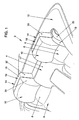
- the four-seat Cabriolet 2 partially shown in Figures 1 and 2 of the drawing has a rear seat 4 with two seats 6, the backrests 8 are each provided with an integrated retractable headrest 10.
- the headrests 10 are in their lower starting position (Fig. 1 and Fig. 2 right) partially on a rear seats 6 surrounding cover 12, below which a lowered top of the convertible 2 hides.
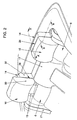
- the associated headrest 10 When loading the seat portion of a seat 6 with a weight of about 25 kg, the associated headrest 10 together with its consisting of two support brackets 13 holder of a arranged in or behind the backrest 8 drive (not shown) vertically into an upper driving position (Fig. 2 left), wherein their height is adjustable in the driving position to adapt to the size of the respective vehicle occupant.
- the headrests 10 are normally in the retracted starting position and are only extended when the associated rear seat 6 is occupied, the wind noise during driving can be reduced in unoccupied rear seats 6 and also a greater contamination of the headrests 10 by insects or dirt particles largely be prevented.
- the lower ends of the head restraints 10 are sunk below the cover 12 in a recess 15 which is bounded in the lateral direction by a middle backrest 17 and a side wall 19, in which a seat belt 21 for the respective rear seat 6 is arranged is.
- each backrest 8 there is arranged in each case a vehicle-resistant rollover protection 14 whose upper end 18 provided with an outer casing 16 is in the initial position of the rollover protection 14 (FIGS. 1 and 2), i. in non-activated state, immediately behind the adjacent headrest 10 is arranged.
- the rollover protection 14 of both seats 6 is activated by a Ausl Harbormechänismus, not shown.
- a roll bar 20 (FIG.
- each rollover protection 14 is pressed in the form of an elongated inverted U of two pretensioned helical compression springs 24 surrounding the hollow legs 22 of the bow 20 upwards into an extended roll over position (not shown), in FIG the top of the panel 16 overhangs the top of the headrest 10.
- the opposite ends of the helical compression springs 24 are supported in each case at the lower end of the legs 22 against a vehicle-fixed abutment and at its upper end against an annular shoulder 27 of the respective leg 22, which is guided vertically displaceably on a guide tube arranged in its interior (not shown) ,
- the arranged on the upper end 18 of the rollover protection 14 panel 16 is in the starting position as far as the headrest 10 on the surrounding cover 12, so that the flattened horizontal tops of the headrest 10 and the panel 16 are substantially aligned in this position.
- the panel 16 and the headrest 10 opposite lateral boundaries 30, 32 which are each arranged in the same, parallel to the direction of travel vertical plane, so that despite the functional separation of the headrest 10 and the clad upper end 18 of the adjacent rollover protection 14 for a viewer of the impression of a related unit arises, which can be supported for example by a matched or matching color or surface finish of the material of a cover of the headrest 10 and the panel 16 yet.
- the parting line 26 between the back of the headrest 10 and the front of the panel 16 has a three-dimensional course, so that in the lateral and vertical direction no view between the headrest 10 and the upper end 18 of the rollover protection 14 is possible.
- a cushion 33 of the headrest 10 has a rearwardly projecting, in cross-section triangular projection 34 which overlaps an adjacent chamfered Ekke 36 of the panel 16, so that the parting line 26 of a transversely to the direction of travel extending lower central part 38, and one on both sides and top around the middle part 38 encircling, obliquely rearwardly oriented edge portion 40 composed.
- the projection 34 is in the vicinity of its tip 42 along a narrow, substantially linear contact 44 against the panel 16, wherein the contact 44 extends at a small distance from the vertical lateral or horizontal upper boundaries of the headrest 10 and the panel 16 over its entire height or width, so that the parting line 26 is almost invisible.
- the edge portion 40 of the parting line 26 gradually widens inwardly toward its middle portion 38, where the distance between the back of the headrest 10 and the front of the panel 16 and thus the joint thickness is greatest.
- the preloaded helical compression springs 24 are released from the trigger mechanism so that they press the roll bar at high speed on the guide tubes in the legs 22 upwards into the roll position in which its upper clad end 18 projects beyond the headrest 10.
- the projection 34 is deformed at the top of the headrest 10 and pushed to the side without the movement of the rollover protection 14 is impaired because of the slight deformability of the cushioning material 33.
Landscapes
- Engineering & Computer Science (AREA)
- Mechanical Engineering (AREA)
- Aviation & Aerospace Engineering (AREA)
- Transportation (AREA)
- Seats For Vehicles (AREA)
Claims (12)
- Cabriolet muni d'au moins un siège (6), d'un arceau de sécurité (14) disposé derrière lui, et d'un appui-tête (10) réglable en hauteur indépendamment de l'arceau de sécurité (14), une extrémité supérieure (18) de l'arceau de sécurité (14) étant disposée derrière un appui-tête (10) du siège dans une position de départ et l'appui-tête (10) et l'extrémité supérieure (18) de l'arceau de sécurité (14) pouvant être déplacés l'un par rapport à l'autre afin de permettre un mouvement relatif entre l'extrémité supérieure (18) de l'arceau de sécurité (14) et l'appui-tête (10) dans le cas de l'activation de l'arceau de sécurité (14) ou d'un réglage en hauteur de l'appui-tête (10) depuis la position de départ, caractérisé en ce que l'appui-tête (10) est connecté au siège et en ce qu'une ligne de joint (26) s'étendant dans la direction latérale et verticale entre l'appui-tête (10) et l'extrémité supérieure (18) de l'arceau de sécurité (14) présente une allure tridimensionnelle telle qu'aucune visibilité n'est possible entre l'appui-tête (10) et l'extrémité supérieure adjacente (18) de l'arceau de sécurité (14), l'appui-tête (10) présentant au moins le long d'une partie de sa délimitation supérieure extérieure (30) une saillie (34) se projetant vers l'arrière, qui chevauche sensiblement horizontalement une partie de l'extrémité supérieure (18) de l'arceau de sécurité (14).
- Cabriolet selon la revendication 1, caractérisé en ce que la ligne de joint (26) présente, à côté de délimitations extérieures visibles (30, 32) de l'appui-tête (10) et de l'extrémité supérieure (18) de l'arceau de sécurité (14) une plus faible épaisseur de joint que dans une région interne (38) disposée entre elles.
- Cabriolet selon la revendication 1 ou 2, caractérisé en ce que l'appui-tête (10) et l'extrémité supérieure (18) de l'arceau de sécurité (14) s'appliquent l'un contre l'autre au niveau de leurs délimitations visibles (30, 32) le long de la ligne de joint (26).
- Cabriolet selon l'une quelconque des revendications 1 à 3, caractérisé en ce que l'appui-tête (10) et l'extrémité supérieure (18) de l'arceau de sécurité (14) présentent la même largeur sensiblement sur toute la hauteur.
- Cabriolet selon l'une quelconque des revendications 1 à 4, caractérisé en ce que l'appui-tête (10) présente au moins le long d'une partie de ses délimitations latérales extérieures (30) une saillie (34) se projetant vers l'arrière, qui chevauche sensiblement verticalement une partie de l'extrémité supérieure (18) de l'arceau de sécurité (14).
- Cabriolet selon l'une quelconque des revendications 1 à 5, caractérisé en ce que la saillie (34) est déformable au moins le long du côté supérieur de l'appui-tête (10) et en ce que l'extrémité supérieure (18) de l'arceau de sécurité (14) se déplace vers le haut lors de son activation par déformation de la saillie (34), jusqu'à ce qu'elle dépasse l'appui-tête (10).
- Cabriolet selon l'une quelconque des revendications 1 à 6, caractérisé en ce que la saillie (34) se rétrécit vers l'arrière.
- Cabriolet selon l'une quelconque des revendications 1 à 7, caractérisé en ce que la saillie (34) s'applique au niveau de ou à proximité de son extrémité arrière contre l'extrémité supérieure (18) de l'arceau de sécurité (14).
- Cabriolet selon l'une quelconque des revendications 1 à 8, caractérisé en ce que l'extrémité supérieure (18) de l'arceau de sécurité (14) est pourvue d'un habillage (16).
- Cabriolet selon l'une quelconque des revendications 1 à 9, caractérisé en ce que l'appui-tête (10) est sorti dans le cas du dépassement d'une force de poids prédéfinie sur une partie de siège du siège (6).
- Cabriolet selon l'une quelconque des revendications 1 à 10, caractérisé en ce que l'arceau de sécurité (14) est ancré derrière le siège (6) et de manière séparée de celui-ci.
- Cabriolet selon l'une quelconque des revendications 1 à 11, caractérisé en ce que l'appui-tête (10) est intégré dans le dossier (8) du siège (6).
Applications Claiming Priority (2)
| Application Number | Priority Date | Filing Date | Title |
|---|---|---|---|
| DE19803398A DE19803398A1 (de) | 1998-01-29 | 1998-01-29 | Cabriolet mit Kopfstütze und Überrollschutz an mindestens einem Sitz |
| DE19803398 | 1998-01-29 |
Publications (3)
| Publication Number | Publication Date |
|---|---|
| EP0933262A1 EP0933262A1 (fr) | 1999-08-04 |
| EP0933262B1 EP0933262B1 (fr) | 2003-03-19 |
| EP0933262B2 true EP0933262B2 (fr) | 2006-10-04 |
Family
ID=7856006
Family Applications (1)
| Application Number | Title | Priority Date | Filing Date |
|---|---|---|---|
| EP98122592A Expired - Lifetime EP0933262B2 (fr) | 1998-01-29 | 1998-12-04 | Cabriolet équipé d'un appui-tête et d'un arceau de sécurité sur au moins un siège |
Country Status (2)
| Country | Link |
|---|---|
| EP (1) | EP0933262B2 (fr) |
| DE (2) | DE19803398A1 (fr) |
Families Citing this family (2)
| Publication number | Priority date | Publication date | Assignee | Title |
|---|---|---|---|---|
| DE19962950C1 (de) * | 1999-12-24 | 2001-03-01 | Daimler Chrysler Ag | Überrollschutzsystem für Kraftfahrzeuge |
| FR2845047B1 (fr) * | 2002-09-30 | 2005-09-09 | Faurecia Sieges Automobile | Appui-tete de vehicule automobile pourvu d'un arceau de securite deployable |
Family Cites Families (11)
| Publication number | Priority date | Publication date | Assignee | Title |
|---|---|---|---|---|
| DE2513022A1 (de) * | 1975-03-25 | 1976-10-07 | Daimler Benz Ag | Kopfstuetze fuer rueckenlehnen, insbesondere von kraftwagensitzen |
| DE3822461A1 (de) * | 1988-07-02 | 1990-01-04 | Daimler Benz Ag | Kopfstuetze fuer fahrzeugsitze |
| DE3903459A1 (de) * | 1989-02-06 | 1990-08-23 | Audi Ag | Kraftwagen in cabrio-bauweise mit einem ueberrollbuegel |
| DE3922509A1 (de) | 1989-07-08 | 1991-01-17 | Daimler Benz Ag | Kopfstuetze fuer ruecksitze |
| DE3927265C3 (de) | 1989-08-18 | 2003-03-27 | Ise Gmbh | Insassenschutzeinrichtung für Kraftfahrzeuge mit einem Überrollbügel |
| DE3930171C2 (de) * | 1989-09-09 | 1996-02-01 | Keiper Recaro Gmbh Co | Überrollschutz |
| DE4017778A1 (de) * | 1990-06-01 | 1991-12-05 | Bayerische Motoren Werke Ag | Antrieb fuer einen ueberrollbuegel eines kraftfahrzeuges |
| DE4237348A1 (en) | 1991-11-08 | 1993-05-13 | Dieter Peschel | Seat construction for motor vehicle - provision of integral or separate overroll protection element |
| DE9200457U1 (de) * | 1992-01-16 | 1993-05-19 | Visual Communications Ingenieurberatungs GmbH, 81243 München | Kraftfahrzeug-Cabrio mit Überrollschutz |
| DE19523790C2 (de) * | 1995-07-04 | 2000-07-20 | Ise Gmbh | Ausfahrbarer Überrollbügel |
| DE29609735U1 (de) * | 1996-06-03 | 1997-10-02 | Eerenstein, Peter, 42699 Solingen | Sicherheitsvorrichtung an Fahrzeug-Kopfstützen |
-
1998
- 1998-01-29 DE DE19803398A patent/DE19803398A1/de not_active Ceased
- 1998-12-04 EP EP98122592A patent/EP0933262B2/fr not_active Expired - Lifetime
- 1998-12-04 DE DE59807551T patent/DE59807551D1/de not_active Expired - Lifetime
Also Published As
| Publication number | Publication date |
|---|---|
| DE19803398A1 (de) | 1999-08-05 |
| EP0933262B1 (fr) | 2003-03-19 |
| EP0933262A1 (fr) | 1999-08-04 |
| DE59807551D1 (de) | 2003-04-24 |
Similar Documents
| Publication | Publication Date | Title |
|---|---|---|
| DE60020028T2 (de) | Verbesserungen an einem fahrersitz | |
| DE102004017688B4 (de) | Kopfstütze für Automobilsitze | |
| EP1029746A2 (fr) | Arceau de sécurité pour véhicules automobiles | |
| DE3021191A1 (de) | Sicherheitskopfstuetze fuer einen fahrzeugsitz | |
| DE69811672T2 (de) | Einziehbare kopfstütze für kraftwagen | |
| DE102004030462B4 (de) | Sitzanordnung in einem Fahrzeug und Insassenschutzsystem für ein Fahrzeug | |
| EP0933262B2 (fr) | Cabriolet équipé d'un appui-tête et d'un arceau de sécurité sur au moins un siège | |
| DE10334551B3 (de) | Kopfstütze für die Rückenlehne von Automobilsitzen, insbesondere von Rücksitzen | |
| DE4325306C2 (de) | Windschottanordnung für ein Cabriolet | |
| DE10125757A1 (de) | Fahrzeugsitz mit einer in der Rückenlehne integrierten Kopfstütze | |
| DE19937028A1 (de) | Fahrzeug mit einer Konsole für die Beifahrerseite | |
| DE19606605A1 (de) | Fahrzeug | |
| DE102015202235A1 (de) | Fahrzeug mit einem Fahrzeugsitz | |
| DE10026340C1 (de) | Anordnung von Airbags bei einem Kraftfahrzeug mit Überrollbügel | |
| DE102012007841B4 (de) | Anordnung einer Sonnenschutzeinrichtung an einem Dach eines Kraftwagens | |
| DE10058518A1 (de) | Fahrzeugsitz | |
| AT414229B (de) | Überrollschützsystem für fahrzeuge | |
| DE19951590C1 (de) | Überrollschutzsystem für Kraftfahrzeuge | |
| DE69628531T2 (de) | Fahrzeugrücksitz | |
| EP1939031A1 (fr) | Véhicule automobile avec un siège | |
| DE10300978A1 (de) | Sicherheitskopfstütze | |
| DE102006045516B3 (de) | Fahrzeugsitz, insbesondere Kraftfahrzeugsitz | |
| DE102006056081A1 (de) | Fahrzeugsitz insbesondere für einen Kraftwagen | |
| DE10137825C1 (de) | Anordnung eines Fahrzeugsitzes in einem Fahrzeug | |
| DE10125758A1 (de) | Fahrzeugsitz mit einer in die Rückenlehne integrierbaren Kopfstütze |
Legal Events
| Date | Code | Title | Description |
|---|---|---|---|
| PUAI | Public reference made under article 153(3) epc to a published international application that has entered the european phase |
Free format text: ORIGINAL CODE: 0009012 |
|
| AK | Designated contracting states |
Kind code of ref document: A1 Designated state(s): DE ES FR GB IT |
|
| AX | Request for extension of the european patent |
Free format text: AL;LT;LV;MK;RO;SI |
|
| 17P | Request for examination filed |
Effective date: 20000204 |
|
| AKX | Designation fees paid |
Free format text: DE ES FR GB IT |
|
| GRAG | Despatch of communication of intention to grant |
Free format text: ORIGINAL CODE: EPIDOS AGRA |
|
| GRAG | Despatch of communication of intention to grant |
Free format text: ORIGINAL CODE: EPIDOS AGRA |
|
| GRAH | Despatch of communication of intention to grant a patent |
Free format text: ORIGINAL CODE: EPIDOS IGRA |
|
| 17Q | First examination report despatched |
Effective date: 20020626 |
|
| GRAH | Despatch of communication of intention to grant a patent |
Free format text: ORIGINAL CODE: EPIDOS IGRA |
|
| GRAA | (expected) grant |
Free format text: ORIGINAL CODE: 0009210 |
|
| AK | Designated contracting states |
Designated state(s): DE ES FR GB IT |
|
| PG25 | Lapsed in a contracting state [announced via postgrant information from national office to epo] |
Ref country code: IT Free format text: LAPSE BECAUSE OF FAILURE TO SUBMIT A TRANSLATION OF THE DESCRIPTION OR TO PAY THE FEE WITHIN THE PRESCRIBED TIME-LIMIT;WARNING: LAPSES OF ITALIAN PATENTS WITH EFFECTIVE DATE BEFORE 2007 MAY HAVE OCCURRED AT ANY TIME BEFORE 2007. THE CORRECT EFFECTIVE DATE MAY BE DIFFERENT FROM THE ONE RECORDED. Effective date: 20030319 Ref country code: GB Free format text: LAPSE BECAUSE OF FAILURE TO SUBMIT A TRANSLATION OF THE DESCRIPTION OR TO PAY THE FEE WITHIN THE PRESCRIBED TIME-LIMIT Effective date: 20030319 |
|
| REG | Reference to a national code |
Ref country code: GB Ref legal event code: FG4D Free format text: NOT ENGLISH |
|
| REF | Corresponds to: |
Ref document number: 59807551 Country of ref document: DE Date of ref document: 20030424 Kind code of ref document: P |
|
| GBV | Gb: ep patent (uk) treated as always having been void in accordance with gb section 77(7)/1977 [no translation filed] |
Effective date: 20030319 |
|
| PG25 | Lapsed in a contracting state [announced via postgrant information from national office to epo] |
Ref country code: ES Free format text: LAPSE BECAUSE OF FAILURE TO SUBMIT A TRANSLATION OF THE DESCRIPTION OR TO PAY THE FEE WITHIN THE PRESCRIBED TIME-LIMIT Effective date: 20030930 |
|
| ET | Fr: translation filed | ||
| PLBI | Opposition filed |
Free format text: ORIGINAL CODE: 0009260 |
|
| PLAX | Notice of opposition and request to file observation + time limit sent |
Free format text: ORIGINAL CODE: EPIDOSNOBS2 |
|
| 26 | Opposition filed |
Opponent name: DAIMLERCHRYSLER AG Effective date: 20031218 |
|
| PLBB | Reply of patent proprietor to notice(s) of opposition received |
Free format text: ORIGINAL CODE: EPIDOSNOBS3 |
|
| PUAH | Patent maintained in amended form |
Free format text: ORIGINAL CODE: 0009272 |
|
| STAA | Information on the status of an ep patent application or granted ep patent |
Free format text: STATUS: PATENT MAINTAINED AS AMENDED |
|
| 27A | Patent maintained in amended form |
Effective date: 20061004 |
|
| AK | Designated contracting states |
Kind code of ref document: B2 Designated state(s): DE ES FR GB IT |
|
| REG | Reference to a national code |
Ref country code: ES Ref legal event code: FD2A Effective date: 20031205 |
|
| ET3 | Fr: translation filed ** decision concerning opposition | ||
| PGFP | Annual fee paid to national office [announced via postgrant information from national office to epo] |
Ref country code: FR Payment date: 20110117 Year of fee payment: 13 Ref country code: DE Payment date: 20110111 Year of fee payment: 13 |
|
| REG | Reference to a national code |
Ref country code: DE Ref legal event code: R082 Ref document number: 59807551 Country of ref document: DE |
|
| REG | Reference to a national code |
Ref country code: FR Ref legal event code: ST Effective date: 20120831 |
|
| REG | Reference to a national code |
Ref country code: DE Ref legal event code: R119 Ref document number: 59807551 Country of ref document: DE Effective date: 20120703 |
|
| PG25 | Lapsed in a contracting state [announced via postgrant information from national office to epo] |
Ref country code: DE Free format text: LAPSE BECAUSE OF NON-PAYMENT OF DUE FEES Effective date: 20120703 |
|
| PG25 | Lapsed in a contracting state [announced via postgrant information from national office to epo] |
Ref country code: FR Free format text: LAPSE BECAUSE OF NON-PAYMENT OF DUE FEES Effective date: 20120102 |