EP0932978B1 - Apparatus and method for generating on-screen-display messages using line doubling - Google Patents
Apparatus and method for generating on-screen-display messages using line doubling Download PDFInfo
- Publication number
- EP0932978B1 EP0932978B1 EP96936523A EP96936523A EP0932978B1 EP 0932978 B1 EP0932978 B1 EP 0932978B1 EP 96936523 A EP96936523 A EP 96936523A EP 96936523 A EP96936523 A EP 96936523A EP 0932978 B1 EP0932978 B1 EP 0932978B1
- Authority
- EP
- European Patent Office
- Prior art keywords
- osd
- line
- header
- bitstream
- data
- Prior art date
- Legal status (The legal status is an assumption and is not a legal conclusion. Google has not performed a legal analysis and makes no representation as to the accuracy of the status listed.)
- Revoked
Links
Images

Classifications
-
- H—ELECTRICITY
- H04—ELECTRIC COMMUNICATION TECHNIQUE
- H04N—PICTORIAL COMMUNICATION, e.g. TELEVISION
- H04N5/00—Details of television systems
- H04N5/44—Receiver circuitry for the reception of television signals according to analogue transmission standards
- H04N5/445—Receiver circuitry for the reception of television signals according to analogue transmission standards for displaying additional information
- H04N5/44504—Circuit details of the additional information generator, e.g. details of the character or graphics signal generator, overlay mixing circuits
-
- H—ELECTRICITY
- H04—ELECTRIC COMMUNICATION TECHNIQUE
- H04N—PICTORIAL COMMUNICATION, e.g. TELEVISION
- H04N5/00—Details of television systems
- H04N5/44—Receiver circuitry for the reception of television signals according to analogue transmission standards
- H04N5/445—Receiver circuitry for the reception of television signals according to analogue transmission standards for displaying additional information
-
- G—PHYSICS
- G09—EDUCATION; CRYPTOGRAPHY; DISPLAY; ADVERTISING; SEALS
- G09G—ARRANGEMENTS OR CIRCUITS FOR CONTROL OF INDICATING DEVICES USING STATIC MEANS TO PRESENT VARIABLE INFORMATION
- G09G5/00—Control arrangements or circuits for visual indicators common to cathode-ray tube indicators and other visual indicators
- G09G5/22—Control arrangements or circuits for visual indicators common to cathode-ray tube indicators and other visual indicators characterised by the display of characters or indicia using display control signals derived from coded signals representing the characters or indicia, e.g. with a character-code memory
- G09G5/24—Generation of individual character patterns
- G09G5/26—Generation of individual character patterns for modifying the character dimensions, e.g. double width, double height
-
- H—ELECTRICITY
- H04—ELECTRIC COMMUNICATION TECHNIQUE
- H04N—PICTORIAL COMMUNICATION, e.g. TELEVISION
- H04N21/00—Selective content distribution, e.g. interactive television or video on demand [VOD]
- H04N21/40—Client devices specifically adapted for the reception of or interaction with content, e.g. set-top-box [STB]; Operations thereof
- H04N21/43—Processing of content or additional data, e.g. demultiplexing additional data from a digital video stream; Elementary client operations, e.g. monitoring of home network or synchronising decoder's clock; Client middleware
- H04N21/434—Disassembling of a multiplex stream, e.g. demultiplexing audio and video streams, extraction of additional data from a video stream; Remultiplexing of multiplex streams; Extraction or processing of SI; Disassembling of packetised elementary stream
-
- G—PHYSICS
- G09—EDUCATION; CRYPTOGRAPHY; DISPLAY; ADVERTISING; SEALS
- G09G—ARRANGEMENTS OR CIRCUITS FOR CONTROL OF INDICATING DEVICES USING STATIC MEANS TO PRESENT VARIABLE INFORMATION
- G09G2340/00—Aspects of display data processing
- G09G2340/10—Mixing of images, i.e. displayed pixel being the result of an operation, e.g. adding, on the corresponding input pixels
-
- H—ELECTRICITY
- H04—ELECTRIC COMMUNICATION TECHNIQUE
- H04N—PICTORIAL COMMUNICATION, e.g. TELEVISION
- H04N7/00—Television systems
- H04N7/01—Conversion of standards, e.g. involving analogue television standards or digital television standards processed at pixel level
- H04N7/0117—Conversion of standards, e.g. involving analogue television standards or digital television standards processed at pixel level involving conversion of the spatial resolution of the incoming video signal
- H04N7/012—Conversion between an interlaced and a progressive signal
Definitions
- the present invention relates to a method and apparatus for generating On-Screen-Display (OSD) messages using a line doubling mode. More particularly, this invention relates to a method and apparatus that reduces the memory bandwidth requirements of a decoding/displaying system by repeating each OSD line on the next line of video for an OSD region.
- OSD On-Screen-Display
- On-Screen-Display messages play an important role in consumer electronics products by providing users with interactive information such as menus to guide them through the usage and configuration of the product.
- Other important features of OSD include the ability to provide Closed Captioning and the display of channel logos.
- HDTV High Definition Television
- NTSC National Television Systems Committee
- the microprocessor of the decoding/displaying system must assign a portion of the memory bandwidth to perform OSD functions, thereby increasing the memory bandwidth requirements of a decoding/displaying system and the overall computational overhead.
- OSD On-Screen-Display
- WO 94/29840 discloses a device for providing programmable on-screen displays for a subscriber terminal.
- the on-screen displays are generated by a display processor from stored screen information and display attributes.
- the on-screen display information and attributes may be stored in a memory, the memory being either within the device or a plug in module connectable to the device.
- the on-screen display information and attributes may also be downloaded from a system manager of the subscription system into a non-volatile memory of the subscriber terminal.
- the on-screen display information and attributes may also be varied using a high level screen display language.
- a Universal High Performance Digital Performance Television Controller discloses an OSD system capable of producing low resolution displays and high resolution displays.
- the system includes two 6 shifters. In high resolution, the shifters are alternately shifting out the dots. In low resolution, the shifters are loaded with the current and the next display line to implement half dot shifts on two diagonally adjacent dots to smooth the characters.
- the invention concerns an apparatus and concomitant method for generating OSD messages by constructing a valid OSD bitstream with instructions in the OSD header to repeat each OSD line.
- the invention relates to a method for constructing an On-Screen Display (OSD) bitstream, said method comprising the steps of:
- the invention also relates to an OSD bitstream stored in a storage medium comprising a header portion having a bit to indicate a line doubling mode; and an OSD data portion, coupled to said header, having OSD data representing every other OSD line in response to the line doubling mode being set.
- the invention further relates to an apparatus for generating an OSD bitstream comprising:
- the invention also relates to an apparatus for generating an OSD message comprising:
- an OSD unit retrieves an OSD bitstream from a storage device.
- the OSD bitstream contains an OSD header and OSD data.
- the OSD header contains control information that is used to program a color palette of the OSD unit and to provide instructions as to the treatment of the OSD data.
- the control information is programmed by a processor of a decoding/displaying system. If the "Line Doubling Mode" is enabled in the OSD header, then the OSD unit will repeat the OSD data such that each OSD line is repeated.
- An OSD line represents a line of OSD pixels in an OSD region. Thus, the OSD unit receives "x" lines of OSD data, and, in turn, displays "2x" lines of OSD data.
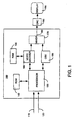
- FIG. 1 illustrates a block diagram of a decoding/displaying system for television signals 100 (hereinafter decoding system).
- the decoding system comprises a processor 130, a random access memory (RAM) 140, a read-only memory (ROM) 142, an OSD unit 150, a video decoder 160, and a mixer 170.
- the output of the mixer 170 is coupled to a display device 190 via path 180.
- the decoding system 100 performs real time audio and video decompression of various data streams (bitstreams) 120.
- the bitstreams 120 may comprise audio and video elementary streams that are encoded in compliance with the MPEG-1 and MPEG-2 standards.
- the encoded bitstreams 120 are generated by an encoder (not shown) and are transmitted to the decoding system through a communication channel.
- the encoded bitstreams contain a coded representation of a plurality of images and may include the audio information associated with those images, e.g., a multimedia data stream.
- the multimedia source may be a HDTV station, a video disk, a cable television station and the like.
- the decoding system 100 decodes the encoded bitstreams to produce a plurality of decoded images for presentation on the display 190 in synchronization with the associated audio information.
- the audio decoding function of the decoding system 100 is irrelevant and, therefore, not discussed.
- processor 130 receives bitstreams 120 and bitstreams 110 as inputs.
- Bitstreams 110 may comprise various control signals or other data streams that are not included in the bitstreams 120.
- a channel decoder or transport unit (not shown) can be deployed between the transmission channel and the decoding system 100 to effect the parsing and routing of data packets into data streams or control streams.
- processor 130 performs various control functions, including but not limited to, providing control data to the video decoder 160 and OSD unit 150, managing access to the memory and controlling the display of the decoded images.
- processor 130 may comprise various dedicated devices to manage specific functions, e.g., a memory controller, a microprocessor interface unit and the like.
- Processor 130 receives bitstreams 120 and writes the data packets into the memory 140 via video decoder 160.
- the bitstreams may optionally pass through a First-In-First-Out (FIFO) buffer (not shown) before being transferred via a memory data bus to the memory.
- FIFO First-In-First-Out
- the memory 140 is used to store a plurality of data including compressed data, decoded images and the OSD bit map. As such, the memory is generally mapped into various buffers, e.g., a bit buffer for storing compressed data, an OSD buffer for storing the OSD bit map, various frame buffers for storing frames of images and a display buffer for storing decoded images.
- various buffers e.g., a bit buffer for storing compressed data, an OSD buffer for storing the OSD bit map, various frame buffers for storing frames of images and a display buffer for storing decoded images.
- the video decoder 160 decodes the compressed data in the memory 140 to reconstruct the encoded images in the memory.
- the decoded image is a difference signal that is added to a stored reference image to produce the actual image in accordance with the compression technique used to encode the image (e.g., to facilitate decoding a motion compensated image).
- the compression technique used to encode the image e.g., to facilitate decoding a motion compensated image.
- the OSD unit 150 uses the memory 140 to store the OSD bit map or the OSD specification.
- the OSD unit allows a user (manufacturer) to define a bit map for each field which can be superimposed on the decoded image.
- the OSD bit map may contain information which is stored in a storage device, e.g., a ROM, concerning the configuration and options of a particular consumer electronics product.
- the OSD bit map may contain information relating to Closed Captioning and channel logos that are transmitted from a cable television, a video disk and the like.
- An OSD bit map is defined as a set of regions (generally in rectangular shapes) of programmable position and size, each of which has a unique palette of available colors.
- the OSD bit map is written into the OSD buffer of the memory 140 which is assigned for this purpose by the user.
- a ROM 142 or other equivalent storage devices can also serve this function as well.
- the processor 130 manipulates the data in memory 140 to construct an OSD bitstream.
- the OSD bitstream contains an OSD header and OSD data (data defining the OSD pixels).
- the processor 130 programs (formats and stores) the OSD header in the memory 140.
- the OSD header contains information concerning the locations of the top and bottom OSD field bit maps, palette data, pointer to the next header block and various display modes involving OSD resolution, color and compression.
- the processor 130 may manipulate the OSD data in the memory 140 in accordance with a particular implementation. For example, the OSD data is formatted in accordance with a selected mode, e.g., the Line Doubling Mode as discussed below.
- the processor may simply program the OSD header with pointers to the OSD data in the memory, where the stored OSD data is retrieved without modification to form the OSD bitstream.
- the processor 130 then reports the enable status, e.g., OSD active, to the OSD unit 150, which responds by requesting the processor 130 for access to the OSD bitstream stored within the memory 140.
- the OSD bitstream is formed and retrieved as the OSD unit 150 reads the OSD headers, each followed by its associated OSD data.
- the OSD unit processes the OSD pixel data in accordance with the instructions or selected modes in the OSD header.
- the OSD unit then waits for a pair of display counters (not shown) to attain count values that identifies the correct position on the display for inserting the OSD information (messages). At the correct position, the OSD unit forwards its output to the mixer 170.
- the output of the OSD unit 150 is a stream or sequence of digital words representing respective luminance and chrominance components of the on screen display. New memory accesses are requested as required to maintain the necessary data flow (OSD bitstream) through the OSD unit to produce a comprehensive OSD display.
- OSD bitstream the necessary data flow
- the OSD header can be read from the memory as the processor is formatting the OSD data, or the OSD data can be processed and displayed as OSD messages by the OSD unit without having to retrieve the entire OSD bitstream.
- the mixer 170 serves to selectively blend or multiplex the decoded image with the OSD pixel data. Namely, the mixer 170 has the capability to display at each pixel location, an OSD pixel, a pixel of the decoded image or a combination (blended) of both types of pixels. This capability permits the display of Closed Captioning (OSD pixel data only) or the display of transparent channel logos (a combination of both OSD pixels and decoded image pixels) on a decoded image.
- OSD pixel data is superimposed on the decoded image
- the mixer 170 serves to selectively blend or multiplex the decoded image with the OSD pixel data. Namely, the mixer 170 has the capability to display at each pixel location, an OSD pixel, a pixel of the decoded image or a combination (blended) of both types of pixels. This capability permits the display of Closed Captioning (OSD pixel data only) or the display of transparent channel logos (a combination of both OSD pixels and decode
- Video decoder 160 and OSD unit 150 both form streams or sequences of digital words representing respective luminance and chrominance components. These sequences of video component representative digital words are coupled via mixer 170 to a digital-to-analog converter (DAC) 185. The luminance and chrominance representative digital words are converted to analog luminance and chrominance signals by the respective sections of the DAC.
- DAC digital-to-analog converter
- the OSD unit 150 can be used to display a user defined bit map over any part of the displayable screen, independent of the size and location of the active video area.
- This bit map can be defined independently for each field and specified as a collection of OSD regions.
- a region is often a rectangular area specified by its boundary and by a bit map defining its contents.
- the bit map is displayed in a plurality of OSD lines, where each OSD line represents a line of OSD pixels in an OSD region.
- Each region has associated with it a palette defining a plurality of colors (e.g., 4 or 16 colors) which can be used within that region. If required, one of these colors can be transparent, allowing the background to show through as discussed above.
- the present invention reduces the size of the OSD bitstream by implementing the Line Doubling Mode.
- the amount of OSD data that must be read from the memory 140 is reduced by 50%. For example, by placing five (5) lines of OSD data in memory 140, and setting the Line Doubling Mode to be true, the OSD unit 150 produces ten (10) lines within an OSD region on the display output.
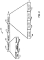
- FIG. 2 illustrates the structure of a sample OSD bitstream 200 using the Line Doubling Mode.
- the OSD bitstream comprises a plurality of OSD headers 210, each followed by OSD data 220.
- the header is comprised of five 64-bit words, followed by any number of 64-bit OSD data (bit map) words.
- the OSD header 210 contains information relating to the OSD region coordinates 214, the various entries of the palette 216 for a particular OSD region, and various function codes (bits) 212.
- bits function codes
- a longer header can provide more information and options, e.g., a palette with more entries, but at the expense of incurring a higher computational overhead, i.e., more read and write cycles are required to implement the OSD functions.
- the content of the OSD header is illustrative of a particular embodiment and is not limited to the specific arrangement as illustrated in FIG. 2.
- the OSD region coordinates 214 contain the positions of the left and right edge of an OSD region, i.e., row start and stop positions and column start and stop positions.
- the region coordinates include the positions (pointers) of the top and bottom field pixel bit maps for the corresponding OSD region.
- the OSD region coordinates 214 include a pointer to the next header block in the memory.
- the palette 216 contains a plurality of entries where each entry contains a representation of chrominance and luminance levels for an OSD pixel.
- the palette information 216 is used to program the OSD palette. Since each OSD header contains palette information 216, the available colors can be selectively changed for each OSD header and its associated OSD data bytes.
- the function codes (bits) 212 contain information relating to various modes, including but not limited to, display options and OSD bitstream options.
- the function bits contain a single bit to indicate whether the "Line Doubling Mode" is enabled.
- the OSD unit will repeat the OSD data such that each OSD line is repeated.
- the processor 130 is only required to generate one-half of the OSD data. Namely, the size of the OSD bitstream is reduced by approximately 50%.
- the OSD data 220 contains bit map data in left to right and top to bottom order.
- the OSD data is generally used to define the color index to the OSD palette for each pixel in the bit map imagery.
- the OSD data 220 defines a plurality of data bytes which are represented by a plurality of OSD lines 230 (OSD pixel lines).
- the length of an OSD line depends on the size of an OSD region.
- Each OSD line contains sufficient OSD data for the OSD unit 150 to display a single horizontal line of OSD pixels in an OSD region.
- the OSD bitstream only carries OSD data for every other OSD line (alternating OSD pixel lines)(e.g., lines 1, 3, 5, 7, ..., as illustrated in FIG. 2).
- This mode of operation allows the processor 130 to gain a 2:1 compression ratio over the normal display mode where the OSD bitstream carries OSD data for all OSD lines.
- the saving is more significant where the OSD regions are particularly large.
- the OSD display resolution is vertically reduced by 50%, since each successive pair of horizontal OSD lines displays the same information.
- a reduction in OSD resolution in exchange for a higher OSD message display rate is acceptable and appropriate for various OSD implementations, e.g., Closed Captioning.
- Closed Captioning requires the rapid display of OSD messages that generally correlate to words spoken for a series of frames (images). Since it is desirable to view the Closed Captioning as the images are displayed, the reduction in resolution is an acceptable tradeoff. Furthermore, since the OSD messages within the Closed Captioning are displayed only briefly, the reduced resolution is generally not noticeable. Thus, the Line Doubling Mode decreases the number of memory operations without limiting the display capabilities of a particular OSD implementation.
- the OSD unit 150 supports multiple header blocks which can each have a different resolution mode.
- the OSD unit is able to display different types of resolution or formats on the same video screen. For example, the borders and various portions of a single OSD region can be displayed in a lower resolution. Similarly, different OSD regions can be displayed in different resolutions depending on the OSD data being displayed.
- the selection of the Line Doubling Mode is controlled by the user via the processor 130.
- This control can be implemented using software that detects the need to minimize memory access by the OSD unit 150.
- the video decoder 160 may receive a series of complicated encoded frames that require additional memory access.
- the processor can offset the increased demand of the video decoder by enabling the Line Doubling Mode in the OSD bitstream.
- FIG. 3 illustrates a method 300 for constructing an OSD bitstream with the Line Doubling Mode.
- the method is generally recalled from a storage device, e.g., a memory, and executed by the processor 130.
- the OSD bitstream is generated by the processor 130 and is processed by the OSD unit 150.
- Method 300 constructs an OSD bitstream by generating an OSD header having a line doubling mode bit, followed by a plurality of data bytes.
- the method 300 begins at step 305 and proceeds to step 310 where a bit in the OSD header is designated as a line doubling mode bit. If the Line Doubling Mode is enabled in the OSD header, then the OSD data bytes represent a plurality of OSD lines, where each OSD line is repeated upon display by the OSD unit. If the Line Doubling Mode is not enabled, then the OSD data bytes are treated in accordance with a normal format, where the OSD lines are displayed by the OSD unit without repetition.
- step 320 method 300 determines whether the Line Doubling Mode is enabled. If the query is negatively answered, method 300 proceeds to step 325 where the OSD data bytes are generated using a non-line doubling format. Method 300 then proceeds to step 340.
- step 330 a plurality of alternate OSD lines is disposed within the OSD data bytes.
- Each OSD line comprises sufficient OSD pixels for the OSD unit 150 to display a single horizontal line in an OSD region. Namely, the OSD bitstream only carries OSD data for every other OSD line.
- step 340 method 300 determines whether there is another OSD header.
- a new OSD header may be required if the various modes represented by the function bits 212 are modified. Similarly, a new header is required for each new OSD region on a frame. If the query is negatively answered, method 300 proceeds to step 350 where method 300 ends. If the query is affirmatively answered, method 300 proceeds to step 320 where the steps of 320-330 are repeated for each additional OSD header. In this manner, the OSD bitstream may comprise both line doubling OSD data bytes and non-line doubling OSD data bytes.
Landscapes
- Engineering & Computer Science (AREA)
- Multimedia (AREA)
- Signal Processing (AREA)
- General Physics & Mathematics (AREA)
- Theoretical Computer Science (AREA)
- Physics & Mathematics (AREA)
- Computer Hardware Design (AREA)
- Computer Graphics (AREA)
- Controls And Circuits For Display Device (AREA)
- Studio Circuits (AREA)
- Transforming Electric Information Into Light Information (AREA)
- Compression Or Coding Systems Of Tv Signals (AREA)
- Control Of Indicators Other Than Cathode Ray Tubes (AREA)
Applications Claiming Priority (1)
| Application Number | Priority Date | Filing Date | Title |
|---|---|---|---|
| PCT/US1996/016514 WO1998017058A1 (en) | 1996-10-16 | 1996-10-16 | Apparatus and method for generating on-screen-display messages using line doubling |
Publications (2)
| Publication Number | Publication Date |
|---|---|
| EP0932978A1 EP0932978A1 (en) | 1999-08-04 |
| EP0932978B1 true EP0932978B1 (en) | 2002-08-14 |
Family
ID=22255962
Family Applications (1)
| Application Number | Title | Priority Date | Filing Date |
|---|---|---|---|
| EP96936523A Revoked EP0932978B1 (en) | 1996-10-16 | 1996-10-16 | Apparatus and method for generating on-screen-display messages using line doubling |
Country Status (11)
| Country | Link |
|---|---|
| EP (1) | EP0932978B1 (pt) |
| JP (1) | JP3935960B2 (pt) |
| KR (1) | KR100413869B1 (pt) |
| AU (1) | AU7433996A (pt) |
| BR (1) | BR9612749A (pt) |
| DE (1) | DE69623055T2 (pt) |
| ES (1) | ES2180803T3 (pt) |
| ID (1) | ID18563A (pt) |
| MY (1) | MY121688A (pt) |
| TW (1) | TW358297B (pt) |
| WO (1) | WO1998017058A1 (pt) |
Families Citing this family (8)
| Publication number | Priority date | Publication date | Assignee | Title |
|---|---|---|---|---|
| FR2784532B1 (fr) * | 1998-10-09 | 2000-12-22 | St Microelectronics Sa | Procede de correction de l'effet de tremblement et de scintillement des elements d'image incrustes sur une image video |
| FR2784534B1 (fr) * | 1998-10-09 | 2000-12-22 | St Microelectronics Sa | Procede et circuit d'affichage d'elements d'image incrustes sur une image video |
| EP1069770B1 (en) * | 1999-07-13 | 2005-11-23 | Thomson Licensing | Method and system for processing video incorporating multiple on screen display formats |
| US6750918B2 (en) * | 2000-05-12 | 2004-06-15 | Thomson Licensing S.A. | Method and system for using single OSD pixmap across multiple video raster sizes by using multiple headers |
| US7202912B2 (en) * | 2000-05-12 | 2007-04-10 | Thomson Licensing | Method and system for using single OSD pixmap across multiple video raster sizes by chaining OSD headers |
| EP1619886A1 (en) * | 2004-07-22 | 2006-01-25 | Harman Becker Automotive Systems GmbH | Video format adaptation |
| ITBS20110048A1 (it) * | 2011-04-08 | 2012-10-09 | Aesys Spa | Metodo per arricchire il contenuto informativo di immagini videografiche |
| EP2697707A1 (en) * | 2011-04-11 | 2014-02-19 | Aesys S.p.A. | Method of improving the content of videographic images with encoding of additional contents on a main videographic image |
Family Cites Families (3)
| Publication number | Priority date | Publication date | Assignee | Title |
|---|---|---|---|---|
| US6166728A (en) * | 1992-12-02 | 2000-12-26 | Scientific-Atlanta, Inc. | Display system with programmable display parameters |
| US5534942A (en) * | 1994-06-17 | 1996-07-09 | Thomson Consumer Electronics, Inc. | On screen display arrangement for digital video signal processing system |
| US5640502A (en) * | 1994-08-05 | 1997-06-17 | Thomson Consumer Electronics, Inc. | Bit-mapped on-screen-display device for a television receiver |
-
1996
- 1996-10-16 WO PCT/US1996/016514 patent/WO1998017058A1/en active IP Right Grant
- 1996-10-16 BR BR9612749-0A patent/BR9612749A/pt not_active IP Right Cessation
- 1996-10-16 JP JP51829798A patent/JP3935960B2/ja not_active Expired - Fee Related
- 1996-10-16 ES ES96936523T patent/ES2180803T3/es not_active Expired - Lifetime
- 1996-10-16 EP EP96936523A patent/EP0932978B1/en not_active Revoked
- 1996-10-16 DE DE69623055T patent/DE69623055T2/de not_active Revoked
- 1996-10-16 AU AU74339/96A patent/AU7433996A/en not_active Abandoned
- 1996-10-16 KR KR10-1999-7003264A patent/KR100413869B1/ko not_active IP Right Cessation
-
1997
- 1997-04-09 TW TW086104517A patent/TW358297B/zh active
- 1997-10-15 MY MYPI97005178A patent/MY121688A/en unknown
- 1997-10-15 ID IDP973438A patent/ID18563A/id unknown
Also Published As
| Publication number | Publication date |
|---|---|
| JP3935960B2 (ja) | 2007-06-27 |
| EP0932978A1 (en) | 1999-08-04 |
| KR100413869B1 (ko) | 2004-01-07 |
| WO1998017058A1 (en) | 1998-04-23 |
| DE69623055D1 (de) | 2002-09-19 |
| ES2180803T3 (es) | 2003-02-16 |
| ID18563A (id) | 1998-04-23 |
| DE69623055T2 (de) | 2003-07-24 |
| MY121688A (en) | 2006-02-28 |
| AU7433996A (en) | 1998-05-11 |
| TW358297B (en) | 1999-05-11 |
| JP2001502492A (ja) | 2001-02-20 |
| KR20000049169A (ko) | 2000-07-25 |
| BR9612749A (pt) | 1999-08-31 |
Similar Documents
| Publication | Publication Date | Title |
|---|---|---|
| US6175388B1 (en) | Apparatus and method for generating on-screen-display messages using on-bit pixels | |
| EP1154642B1 (en) | A method for using a single osd pixmap across mulitple video raster sizes by chaining osd headers | |
| US6480238B1 (en) | Apparatus and method for generating on-screen-display messages using field doubling | |
| EP1154643B1 (en) | A method and system for using a single osd pixmap across multiple video raster sizes by using multiple headers | |
| US6351292B1 (en) | Apparatus and method for generating on-screen-display messages using line doubling | |
| EP0932978B1 (en) | Apparatus and method for generating on-screen-display messages using line doubling | |
| US6118494A (en) | Apparatus and method for generating on-screen-display messages using true color mode | |
| EP0932977B1 (en) | Apparatus and method for generating on-screen-display messages using field doubling | |
| EP0932976B1 (en) | Apparatus and method for generating on-screen-display messages using one-bit pixels | |
| EP0932982B1 (en) | Apparatus and method for generating on-screen-display messages using true color mode | |
| AU719563C (en) | Apparatus and method for generating on-screen-display messages using field doubling | |
| MXPA99003535A (en) | Apparatus and method for generating on-screen-display messages using field doubling | |
| MXPA99003537A (es) | Aparato y metodo para generar mensajes de despliegue en pantalla usando doblaje de linea | |
| MXPA99003539A (en) | Apparatus and method for generating on-screen-display messages using true color mode | |
| MXPA99003536A (en) | Apparatus and method for generating on-screen-display messages using one-bit pixels |
Legal Events
| Date | Code | Title | Description |
|---|---|---|---|
| PUAI | Public reference made under article 153(3) epc to a published international application that has entered the european phase |
Free format text: ORIGINAL CODE: 0009012 |
|
| 17P | Request for examination filed |
Effective date: 19990331 |
|
| AK | Designated contracting states |
Kind code of ref document: A1 Designated state(s): DE ES FR GB IE IT |
|
| 17Q | First examination report despatched |
Effective date: 20010417 |
|
| GRAG | Despatch of communication of intention to grant |
Free format text: ORIGINAL CODE: EPIDOS AGRA |
|
| GRAG | Despatch of communication of intention to grant |
Free format text: ORIGINAL CODE: EPIDOS AGRA |
|
| GRAH | Despatch of communication of intention to grant a patent |
Free format text: ORIGINAL CODE: EPIDOS IGRA |
|
| GRAH | Despatch of communication of intention to grant a patent |
Free format text: ORIGINAL CODE: EPIDOS IGRA |
|
| GRAA | (expected) grant |
Free format text: ORIGINAL CODE: 0009210 |
|
| AK | Designated contracting states |
Kind code of ref document: B1 Designated state(s): DE ES FR GB IE IT |
|
| REG | Reference to a national code |
Ref country code: GB Ref legal event code: FG4D |
|
| RAP2 | Party data changed (patent owner data changed or rights of a patent transferred) |
Owner name: THOMSON MULTIMEDIA INC. |
|
| REG | Reference to a national code |
Ref country code: IE Ref legal event code: FG4D |
|
| REF | Corresponds to: |
Ref document number: 69623055 Country of ref document: DE Date of ref document: 20020919 |
|
| PG25 | Lapsed in a contracting state [announced via postgrant information from national office to epo] |
Ref country code: IE Free format text: LAPSE BECAUSE OF NON-PAYMENT OF DUE FEES Effective date: 20021016 |
|
| REG | Reference to a national code |
Ref country code: GB Ref legal event code: 746 Effective date: 20030103 |
|
| ET | Fr: translation filed | ||
| REG | Reference to a national code |
Ref country code: ES Ref legal event code: FG2A Ref document number: 2180803 Country of ref document: ES Kind code of ref document: T3 |
|
| PLBQ | Unpublished change to opponent data |
Free format text: ORIGINAL CODE: EPIDOS OPPO |
|
| PLBI | Opposition filed |
Free format text: ORIGINAL CODE: 0009260 |
|
| PLAX | Notice of opposition and request to file observation + time limit sent |
Free format text: ORIGINAL CODE: EPIDOSNOBS2 |
|
| 26 | Opposition filed |
Opponent name: INTERESSENGEMEINSCHAFTFUER RUNDFUNKSCHUTZRECHTE GM Effective date: 20030513 |
|
| REG | Reference to a national code |
Ref country code: IE Ref legal event code: MM4A |
|
| RAP2 | Party data changed (patent owner data changed or rights of a patent transferred) |
Owner name: THOMSON INC. |
|
| PLAX | Notice of opposition and request to file observation + time limit sent |
Free format text: ORIGINAL CODE: EPIDOSNOBS2 |
|
| PLBB | Reply of patent proprietor to notice(s) of opposition received |
Free format text: ORIGINAL CODE: EPIDOSNOBS3 |
|
| PGFP | Annual fee paid to national office [announced via postgrant information from national office to epo] |
Ref country code: ES Payment date: 20071120 Year of fee payment: 12 |
|
| PGFP | Annual fee paid to national office [announced via postgrant information from national office to epo] |
Ref country code: IT Payment date: 20071027 Year of fee payment: 12 |
|
| PG25 | Lapsed in a contracting state [announced via postgrant information from national office to epo] |
Ref country code: IT Free format text: LAPSE BECAUSE OF NON-PAYMENT OF DUE FEES Effective date: 20081016 |
|
| PGFP | Annual fee paid to national office [announced via postgrant information from national office to epo] |
Ref country code: GB Payment date: 20090930 Year of fee payment: 14 |
|
| REG | Reference to a national code |
Ref country code: ES Ref legal event code: FD2A Effective date: 20081017 |
|
| PG25 | Lapsed in a contracting state [announced via postgrant information from national office to epo] |
Ref country code: ES Free format text: LAPSE BECAUSE OF NON-PAYMENT OF DUE FEES Effective date: 20081017 |
|
| PGFP | Annual fee paid to national office [announced via postgrant information from national office to epo] |
Ref country code: DE Payment date: 20091026 Year of fee payment: 14 |
|
| RDAF | Communication despatched that patent is revoked |
Free format text: ORIGINAL CODE: EPIDOSNREV1 |
|
| PGFP | Annual fee paid to national office [announced via postgrant information from national office to epo] |
Ref country code: FR Payment date: 20091117 Year of fee payment: 14 |
|
| RDAG | Patent revoked |
Free format text: ORIGINAL CODE: 0009271 |
|
| STAA | Information on the status of an ep patent application or granted ep patent |
Free format text: STATUS: PATENT REVOKED |
|
| 27W | Patent revoked |
Effective date: 20100310 |
|
| GBPR | Gb: patent revoked under art. 102 of the ep convention designating the uk as contracting state |
Effective date: 20100310 |