EP0932356B1 - Regelbarer zeitschalter mit einem rc-oszillator mit einstellbarem widerstand, sowie brotröster ausgerüstet mit einem solchen zeitschalter - Google Patents
Regelbarer zeitschalter mit einem rc-oszillator mit einstellbarem widerstand, sowie brotröster ausgerüstet mit einem solchen zeitschalter Download PDFInfo
- Publication number
- EP0932356B1 EP0932356B1 EP98917517A EP98917517A EP0932356B1 EP 0932356 B1 EP0932356 B1 EP 0932356B1 EP 98917517 A EP98917517 A EP 98917517A EP 98917517 A EP98917517 A EP 98917517A EP 0932356 B1 EP0932356 B1 EP 0932356B1
- Authority
- EP
- European Patent Office
- Prior art keywords
- oscillator
- timer
- resistor
- series arrangement
- capacitor
- Prior art date
- Legal status (The legal status is an assumption and is not a legal conclusion. Google has not performed a legal analysis and makes no representation as to the accuracy of the status listed.)
- Expired - Lifetime
Links
- 239000003990 capacitor Substances 0.000 claims abstract description 22
- 230000010355 oscillation Effects 0.000 claims abstract description 13
- 230000001419 dependent effect Effects 0.000 claims abstract description 3
- 238000010438 heat treatment Methods 0.000 claims description 5
- 238000005485 electric heating Methods 0.000 claims description 3
- 238000010586 diagram Methods 0.000 description 8
- 235000008429 bread Nutrition 0.000 description 1
- 230000007423 decrease Effects 0.000 description 1
- 238000009499 grossing Methods 0.000 description 1
- 238000000034 method Methods 0.000 description 1
- 239000004065 semiconductor Substances 0.000 description 1
Images


Classifications
-
- A—HUMAN NECESSITIES
- A47—FURNITURE; DOMESTIC ARTICLES OR APPLIANCES; COFFEE MILLS; SPICE MILLS; SUCTION CLEANERS IN GENERAL
- A47J—KITCHEN EQUIPMENT; COFFEE MILLS; SPICE MILLS; APPARATUS FOR MAKING BEVERAGES
- A47J37/00—Baking; Roasting; Grilling; Frying
- A47J37/06—Roasters; Grills; Sandwich grills
- A47J37/08—Bread-toasters
- A47J37/0814—Bread-toasters with automatic bread ejection or timing means
- A47J37/0842—Bread-toasters with automatic bread ejection or timing means with electronic timers
Definitions
- the invention relates to an RC oscillator having a controllable oscillation frequency, comprising: a series arrangement of a capacitor and resistor, and a signal source for supplying a step signal to the series arrangement, the oscillation frequency in operation being dependent upon the time which expires until the capacitor has been charged to a given value.
- the invention further relates to an electric toaster comprising: an electric heating element, means for connecting the heating element to an electric power source, an adjustable timer for disconnecting the heating element from the electric power source after expiry of an adjustable time, the adjustable timer including such an RC oscillator.
- Such an RC oscillator and toaster are known from, for example, European Patent Application EP-A-0 086 624.
- This known toaster has a timer by means of which the toasting time can be set.
- the timer comprises an RC oscillator and a divider circuit which divides the comparatively high oscillation frequency of the RC oscillator to a signal having a low frequency and a period whose length is suitable for toasting.
- the generation of the oscillation frequency is based on the application of a step voltage to a series arrangement of a resistor and a capacitor and on subsequently waiting until the voltage across the capacitor exceeds a given threshold voltage.
- the resistance is varied by means of a potentiometer so as to enable the period of the oscillation frequency to be controlled.
- the threshold voltage is exceeded sooner and the period becomes smaller according as the resistance decreases. Since the resistance of a potentiometer generally has a fairly large tolerance there is a comparatively large spread in the frequency generated by the RC oscillator. If such a potentiometer is now used in the timer of a toaster the toasting time obtained for a given setting of the control knob or slide of the potentiometer will differ from toaster to toaster.
- the RC oscillator of the type defined in the opening paragraph is characterized in that the signal source comprises an adjustable voltage divider, the divider being arranged in parallel to the signal source for dividing the amplitude of the step signal and having an output connected to the series arrangement for supplying a divided step signal to the series arrangement.
- the invention is based on the recognition of the fact that it is the amplitude of the step voltage applied to the series arrangement of the capacitor and the resistor which should be varied, rather than the resistance via which the capacitor is to be charged.
- the amplitude can be varied in various manners, preferably by means of a potentiometer which operates as voltage divider for the step voltage.
- the tolerance of this potentiometer is not relevant because it is now the ratio between two equally inaccurate resistances which matters.
- the step voltage, and hence the oscillation frequency, are now directly proportional to the setting of the potentiometer, regardless of its tolerance.
- the amplitude of the step voltage can also be adjusted in other ways, for example by means a resistor in series with a zener diode which, by means of a switch, is selected from a group of at least two zener diodes having different zener voltages. In this way, it is possible to generate a number of discrete step voltages.
- the RC oscillator in accordance with the invention is suitable for timers in general but particularly for electrical appliances which should be turned off after a given time, such as toasters, sunbeds and the like.
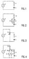
- FIG. 1 shows the circuit diagram illustrating the basic principle of an RC oscillator.
- a capacitor 2 is charged via a resistor 4 by applying a step voltage Us from a voltage source 6.
- a threshold value the capacitor 2 is discharged either in that the capacitor 2 is discharged by means of a switch, as is customary in timer ICs of the type "555”, or in that the step voltage Us is inverted as is customary in timers of the type "4060".
- the time constant of the series arrangement of the capacitor 2 and the resistor 4 determines the frequency of the RC oscillator. In timers having a timing range of the order of seconds or minutes it is customary to reduce the oscillation frequency by means of a frequency divider.
- the frequency can be varied by making the resistance of the resistor 4 adjustable.
- the resistor 4 in the circuit diagram of Figure 2 has been replaced by a fixed resistor 10, a variable resistor 8 arranged in series with this fixed resistor, and a fixed resistor 12 arranged in parallel with the variable resistor 8.
- the variable resistor 8 is usually a rotary or sliding potentiometer, which for cost price reasons generally exhibits a fairly large tolerance on its nominal resistance value.
- the absolute resistance value and, consequently, the time setting of the timer for a given position of the wiper of the potentiometer also have a large tolerance.
- Identical appliances equipped with such a timer will exhibit different time settings for the same position of the timer knob.
- Figure 3 shows a solution to this problem.
- the tolerance problem is solved by not making the series resistor 4 variable but the step voltage Us from the voltage source 6.
- a potentiometer 14 is connected across the voltage source 6 and has its wiper connected to the series arrangement of the capacitor 2 and the resistor 4.
- the wiper of the potentiometer 14 divides the total resistance of the potentiometer into two fractions whose resistance ratio determines the amplitude of the outgoing step voltage.
- the resistance ratio is only determined by the mechanical position of the wiper. Thus, the influence of the tolerance of the variable resistor is eliminated.
- Figure 4 shows a variant in which the step voltage Us from the voltage source 6 is varied by means of a resistor 16 in series with a zener diode.
- the zener diode can be selected from a group of at least two zener diodes 18 and 20 having different zener voltages.
- the zener diodes limit the step voltage to different values. The smaller the zener voltage, the longer it takes before the capacitor 2 is charged to the required threshold voltage and the lower the oscillation frequency is.
- FIG. 5 shows a toaster having an adjustable toasting time.
- the toasting time is adjustable by means of a rotary knob 26 mounted on the spindle of the potentiometer 14.
- Toasting is started by pushing down a handle 28, which lowers the bread into the toasting chamber and also activates the timer circuit of the toaster.
- FIG 6 shows the circuit diagram of the timer circuit of the toaster.
- the toaster has an electric heating element 30, which can be connected to the a.c. mains terminals 34 and 36 via a switch 32.
- the switch 32 is closed when the handle 28 (see Figure 5) is in its fully lowered position.
- the alternating voltage across the heating element 30 is rectified by means of a diode 38 and a smoothing capacitor 40 to provide the supply voltage for a timer IC 42 of the type HEF 4060 (14-Stage Ripple-Carry Binary Counter/Divider and Oscillator) availaLle from Philips Semiconductors or of a similar type.
- HEF 4060 14-Stage Ripple-Carry Binary Counter/Divider and Oscillator
- the timer IC 42 drives a coil 46 via a PNP transistor 44, which coil locks the handle 28 until the time set by means of the knob 26 (see Figure 5) has expired. The handle is then unlocked. As a result of this, the switch 32 is opened and the handle 28 moves upward automatically.
- the timer IC 42 is reset at a pin p12 by means of a capacitor 48 and a resistor 50, as a result of which the output at a pin p3 goes low and the PNP transistor 44 is turned on, causing the coil 46 to be energized.
- a switch 52 By means of a switch 52 the base-emitter junction of the PNP transistor 44 can be short-circuited so as to enable the toasting process to be terminated prematurely.
- the timer IC 42 includes an inverter having an input connected to a pin p10 and having an output connected to a pin p9. In operation the output p9 carries a step voltage which is variable by means of the potentiometer 14 and a limiting resistor 54 between the pin p9 and signal ground.
- variable step voltage on the wiper of the potentiometer 14 is fed back to the input p10 of the inverter via a series arrangement of the capacitor 2 and resistors 56, 58 and 60, a temperature-sensitive resistor 62 being arranged in parallel with the resistor 58 so as to provide a correction for a cold and warm operating condition of the toaster.
- a resistor 64 is connected between a pin p11 of the timer IC 42 and the node between the capacitor 2 and the resistor 58. For the purpose of the resistor 64 and for further details about the timer IC 42 reference is made to the relevant manufacturer's data sheets.
- the internal counter of the timer IC 42 counts the number of periods of the RC oscillator. After some time, adjustable by means of the potentiometer 14, the output at the pin p3 goes high, as a result of which the PNP transistor 44 is turned off. The coil 46 then no longer receives any energizing current, so that the toaster is switched off.
- the timer circuit can be used as a self-contained unit or it can be incorporated in electrical appliances. Obviously, the timer circuit is not only suitable for use in toasters but in all kinds of other appliances which should be turned off automatically after expiry of an adjustable time, such as sunbeds, ovens and the like.
Landscapes
- Engineering & Computer Science (AREA)
- Food Science & Technology (AREA)
- Electric Ovens (AREA)
- Electric Stoves And Ranges (AREA)
- Inductance-Capacitance Distribution Constants And Capacitance-Resistance Oscillators (AREA)
- Oscillators With Electromechanical Resonators (AREA)
- Measurement Of Predetermined Time Intervals (AREA)
Claims (4)
- RC-Oszillator mit einer regelbaren Oszillatorfrequenz, wobei dieser Oszillator die nachfolgenden Elemente umfasst: eine Reihenschaltung aus einem Kondensator (2) und einem Widerstand (4), und eine Signalquelle (6) zum Liefern eines Schrittsignals zu der Reihenschaltung, wobei die Oszillatorfrequenz im Betrieb abhängig ist von der Zeit, die vergeht, bis der Kondensator (2) auf einen bestimmten Wert aufgeladen ist, dadurch gekennzeichnet, dass die Signalquelle (6) einen einstellbaren Spannungsverteiler (14) aufweist, wobei dieser Verteiler zu der Signalquelle (6) parallel geschaltet ist zum Verteilen der Amplitude des Schrittsignals und einen Ausgang hat, der mit der Reihenschaltung verbunden ist zum Liefern eines verteilten Schrittsignals zu der Reihenschaltung.
- RC-Oszillator nach Anspruch 1, dadurch gekennzeichnet, dass der einstellbare Spannungsteiler ein Potentiometer (14) ist mit einem Schieber, der mit der Reihenschaltung (4, 2) gekoppelt ist.
- RC-Oszillator nach Anspruch 1, dadurch gekennzeichnet, dass der einstellbare Spannungsteiler eine weitere Reihenschaltung aus einem weiteren Widerstand (16) und einer Zener-Diode (18) ist, die mit Hilfe eines Schaltmittels (22, 24) aus einer Anzahl von wenigstens zwei Zener-Dioden (18, 20) selektiert werden kann, wobei die erst genannte Reihenschaltung (4, 2) mit einem Knotenpunkt zwischen dem weiteren Widerstand (16) und der Zener-Diode (18) gekoppelt ist.
- Elektrischer Brotröster mit einem elektrischen Heizelement (30), mit Mitteln (32) zum Verbinden des Heizelementes (30) mit einer elektrischen Speisequelle (34, 36), mit einem einstellbaren Zeitschalter (42) zum Entkoppeln des Heizelementes (30) von der elektrischen Speisequelle (34, 36) nach Ablauf einer einstellbaren Zeit, wobei der einstellbare Zeitschalter (42) einen RC-Oszillator nach Anspruch 1, 2 oder 3 umfasst.
Priority Applications (1)
| Application Number | Priority Date | Filing Date | Title |
|---|---|---|---|
| EP98917517A EP0932356B1 (de) | 1997-07-17 | 1998-05-14 | Regelbarer zeitschalter mit einem rc-oszillator mit einstellbarem widerstand, sowie brotröster ausgerüstet mit einem solchen zeitschalter |
Applications Claiming Priority (4)
| Application Number | Priority Date | Filing Date | Title |
|---|---|---|---|
| EP97202250 | 1997-07-17 | ||
| EP97202250 | 1997-07-17 | ||
| EP98917517A EP0932356B1 (de) | 1997-07-17 | 1998-05-14 | Regelbarer zeitschalter mit einem rc-oszillator mit einstellbarem widerstand, sowie brotröster ausgerüstet mit einem solchen zeitschalter |
| PCT/IB1998/000724 WO1999003385A2 (en) | 1997-07-17 | 1998-05-14 | Timer with adjustable time control based on an rc oscillator with a variable resistor, and toaster including such a timer |
Publications (2)
| Publication Number | Publication Date |
|---|---|
| EP0932356A2 EP0932356A2 (de) | 1999-08-04 |
| EP0932356B1 true EP0932356B1 (de) | 2002-12-11 |
Family
ID=8228572
Family Applications (1)
| Application Number | Title | Priority Date | Filing Date |
|---|---|---|---|
| EP98917517A Expired - Lifetime EP0932356B1 (de) | 1997-07-17 | 1998-05-14 | Regelbarer zeitschalter mit einem rc-oszillator mit einstellbarem widerstand, sowie brotröster ausgerüstet mit einem solchen zeitschalter |
Country Status (8)
| Country | Link |
|---|---|
| US (1) | US5938960A (de) |
| EP (1) | EP0932356B1 (de) |
| JP (1) | JP2001500770A (de) |
| CN (1) | CN1241321C (de) |
| AT (1) | ATE229294T1 (de) |
| DE (1) | DE69810071T2 (de) |
| ES (1) | ES2189160T3 (de) |
| WO (1) | WO1999003385A2 (de) |
Families Citing this family (5)
| Publication number | Priority date | Publication date | Assignee | Title |
|---|---|---|---|---|
| US20030198001A1 (en) * | 2002-04-19 | 2003-10-23 | Lawrence Lile | Methods and systems for protecting circuit |
| JP2004053993A (ja) * | 2002-07-22 | 2004-02-19 | Nidec Copal Corp | ズームレンズ |
| US7145108B2 (en) * | 2003-07-22 | 2006-12-05 | Kaz, Incorporated | Configurable heating pad controller |
| CN107968568B (zh) * | 2017-12-12 | 2024-03-12 | 清华四川能源互联网研究院 | 一种低功耗恒定导通时间定时电路设计方法及定时电路 |
| CN112702049B (zh) * | 2020-12-30 | 2025-05-30 | 贵州西南工具(集团)有限公司 | 一种延时时间可以调的机床延时启动电路 |
Family Cites Families (6)
| Publication number | Priority date | Publication date | Assignee | Title |
|---|---|---|---|---|
| US4170932A (en) * | 1977-06-21 | 1979-10-16 | Lionel Lalancette | Electronic toaster control |
| US4376243A (en) * | 1981-01-26 | 1983-03-08 | General Motors Corporation | Arc detector for electric rod furnace |
| EP0086624A1 (de) * | 1982-02-10 | 1983-08-24 | Morphy Richards Limited | Elektrischer Brotröster |
| DE3803571A1 (de) * | 1988-02-06 | 1989-08-17 | Rowenta Werke Gmbh | Elektrisch beheizbarer brotroester |
| US5402708A (en) * | 1994-01-07 | 1995-04-04 | Black & Decker Inc. | Control for a toaster for varying the duration of the toasting cycle |
| US5672288A (en) * | 1996-08-19 | 1997-09-30 | Black & Decker Inc. | Light sensitive control for toaster |
-
1998
- 1998-05-14 CN CN98800983.8A patent/CN1241321C/zh not_active Expired - Fee Related
- 1998-05-14 AT AT98917517T patent/ATE229294T1/de not_active IP Right Cessation
- 1998-05-14 ES ES98917517T patent/ES2189160T3/es not_active Expired - Lifetime
- 1998-05-14 DE DE69810071T patent/DE69810071T2/de not_active Expired - Fee Related
- 1998-05-14 EP EP98917517A patent/EP0932356B1/de not_active Expired - Lifetime
- 1998-05-14 WO PCT/IB1998/000724 patent/WO1999003385A2/en not_active Ceased
- 1998-05-14 JP JP10529468A patent/JP2001500770A/ja not_active Ceased
- 1998-07-14 US US09/115,785 patent/US5938960A/en not_active Expired - Fee Related
Also Published As
| Publication number | Publication date |
|---|---|
| WO1999003385A2 (en) | 1999-01-28 |
| WO1999003385A3 (en) | 1999-04-08 |
| CN1234921A (zh) | 1999-11-10 |
| CN1241321C (zh) | 2006-02-08 |
| ATE229294T1 (de) | 2002-12-15 |
| ES2189160T3 (es) | 2003-07-01 |
| EP0932356A2 (de) | 1999-08-04 |
| JP2001500770A (ja) | 2001-01-23 |
| DE69810071D1 (de) | 2003-01-23 |
| US5938960A (en) | 1999-08-17 |
| DE69810071T2 (de) | 2003-09-04 |
Similar Documents
| Publication | Publication Date | Title |
|---|---|---|
| US5948305A (en) | Multi-function control module for toaster oven appliance | |
| US5981916A (en) | Advanced cooking appliance | |
| US4214151A (en) | Control instrument for electric cooker plates | |
| US4591781A (en) | Variable control circuit having a predetermined timed output | |
| EP0896785B1 (de) | Steuerung für eine elektrische heizanlage, die zu konsistenten heizergebnissen führt | |
| US4443690A (en) | Power control for cooking appliance with transient operating modes | |
| US4486648A (en) | Energy regulator for a household heating appliance for producing variable speed initial heating | |
| EP0932356B1 (de) | Regelbarer zeitschalter mit einem rc-oszillator mit einstellbarem widerstand, sowie brotröster ausgerüstet mit einem solchen zeitschalter | |
| CA2211431C (en) | Light sensitive control for toaster | |
| EP0152971B1 (de) | Temperatursteuerung und Anzeigeeinrichtung | |
| CA2270799C (en) | Infinite temperature control | |
| US4742246A (en) | Preheat timer for use in oven | |
| GB2030799A (en) | Power supplies for cooker plates | |
| CA1130397A (en) | Variable power and temperature control system for a microwave oven | |
| CA2192905A1 (en) | Toaster compensation for repeated use | |
| KR100223345B1 (ko) | 가열장치의 제어장치 | |
| US6198077B1 (en) | Temperature compensated timing circuit for use in heating appliances | |
| JP2932807B2 (ja) | オーブントースタの制御装置 | |
| JP2987537B2 (ja) | 電気調理器とその制御装置 | |
| CA1186772A (en) | Multi-voltage disinfector timing circuit | |
| JPH0323150Y2 (de) | ||
| JPH06243955A (ja) | 電気調理器の制御装置 | |
| JPS59115014A (ja) | 焙焼機用電子タイマ− | |
| EP0827362A2 (de) | Kochverfahren mit Anfangsphase mit variabler Zeitdauer | |
| JPS6149938A (ja) | 自動焙焼装置 |
Legal Events
| Date | Code | Title | Description |
|---|---|---|---|
| PUAI | Public reference made under article 153(3) epc to a published international application that has entered the european phase |
Free format text: ORIGINAL CODE: 0009012 |
|
| 17P | Request for examination filed |
Effective date: 19990419 |
|
| AK | Designated contracting states |
Kind code of ref document: A2 Designated state(s): AT DE ES FR GB IT NL |
|
| 17Q | First examination report despatched |
Effective date: 20010918 |
|
| GRAG | Despatch of communication of intention to grant |
Free format text: ORIGINAL CODE: EPIDOS AGRA |
|
| GRAG | Despatch of communication of intention to grant |
Free format text: ORIGINAL CODE: EPIDOS AGRA |
|
| GRAH | Despatch of communication of intention to grant a patent |
Free format text: ORIGINAL CODE: EPIDOS IGRA |
|
| GRAH | Despatch of communication of intention to grant a patent |
Free format text: ORIGINAL CODE: EPIDOS IGRA |
|
| GRAA | (expected) grant |
Free format text: ORIGINAL CODE: 0009210 |
|
| AK | Designated contracting states |
Kind code of ref document: B1 Designated state(s): AT DE ES FR GB IT NL |
|
| PG25 | Lapsed in a contracting state [announced via postgrant information from national office to epo] |
Ref country code: NL Free format text: LAPSE BECAUSE OF FAILURE TO SUBMIT A TRANSLATION OF THE DESCRIPTION OR TO PAY THE FEE WITHIN THE PRESCRIBED TIME-LIMIT Effective date: 20021211 Ref country code: AT Free format text: LAPSE BECAUSE OF FAILURE TO SUBMIT A TRANSLATION OF THE DESCRIPTION OR TO PAY THE FEE WITHIN THE PRESCRIBED TIME-LIMIT Effective date: 20021211 |
|
| REF | Corresponds to: |
Ref document number: 229294 Country of ref document: AT Date of ref document: 20021215 Kind code of ref document: T |
|
| REG | Reference to a national code |
Ref country code: GB Ref legal event code: FG4D |
|
| REF | Corresponds to: |
Ref document number: 69810071 Country of ref document: DE Date of ref document: 20030123 |
|
| NLV1 | Nl: lapsed or annulled due to failure to fulfill the requirements of art. 29p and 29m of the patents act | ||
| REG | Reference to a national code |
Ref country code: ES Ref legal event code: FG2A Ref document number: 2189160 Country of ref document: ES Kind code of ref document: T3 |
|
| ET | Fr: translation filed | ||
| PLBE | No opposition filed within time limit |
Free format text: ORIGINAL CODE: 0009261 |
|
| STAA | Information on the status of an ep patent application or granted ep patent |
Free format text: STATUS: NO OPPOSITION FILED WITHIN TIME LIMIT |
|
| 26N | No opposition filed |
Effective date: 20030912 |
|
| PGFP | Annual fee paid to national office [announced via postgrant information from national office to epo] |
Ref country code: IT Payment date: 20060531 Year of fee payment: 9 |
|
| PGFP | Annual fee paid to national office [announced via postgrant information from national office to epo] |
Ref country code: DE Payment date: 20060714 Year of fee payment: 9 |
|
| PGFP | Annual fee paid to national office [announced via postgrant information from national office to epo] |
Ref country code: ES Payment date: 20070509 Year of fee payment: 10 |
|
| PGFP | Annual fee paid to national office [announced via postgrant information from national office to epo] |
Ref country code: GB Payment date: 20070522 Year of fee payment: 10 |
|
| PG25 | Lapsed in a contracting state [announced via postgrant information from national office to epo] |
Ref country code: DE Free format text: LAPSE BECAUSE OF NON-PAYMENT OF DUE FEES Effective date: 20071201 |
|
| PGFP | Annual fee paid to national office [announced via postgrant information from national office to epo] |
Ref country code: FR Payment date: 20070529 Year of fee payment: 10 |
|
| GBPC | Gb: european patent ceased through non-payment of renewal fee |
Effective date: 20080514 |
|
| REG | Reference to a national code |
Ref country code: FR Ref legal event code: ST Effective date: 20090119 |
|
| PG25 | Lapsed in a contracting state [announced via postgrant information from national office to epo] |
Ref country code: FR Free format text: LAPSE BECAUSE OF NON-PAYMENT OF DUE FEES Effective date: 20080602 |
|
| PG25 | Lapsed in a contracting state [announced via postgrant information from national office to epo] |
Ref country code: GB Free format text: LAPSE BECAUSE OF NON-PAYMENT OF DUE FEES Effective date: 20080514 |
|
| REG | Reference to a national code |
Ref country code: ES Ref legal event code: FD2A Effective date: 20080516 |
|
| PG25 | Lapsed in a contracting state [announced via postgrant information from national office to epo] |
Ref country code: IT Free format text: LAPSE BECAUSE OF NON-PAYMENT OF DUE FEES Effective date: 20070514 |
|
| PG25 | Lapsed in a contracting state [announced via postgrant information from national office to epo] |
Ref country code: ES Free format text: LAPSE BECAUSE OF NON-PAYMENT OF DUE FEES Effective date: 20080516 |