EP0932018A2 - Dispositif inductif pour mesurer des angles - Google Patents
Dispositif inductif pour mesurer des angles Download PDFInfo
- Publication number
- EP0932018A2 EP0932018A2 EP99100063A EP99100063A EP0932018A2 EP 0932018 A2 EP0932018 A2 EP 0932018A2 EP 99100063 A EP99100063 A EP 99100063A EP 99100063 A EP99100063 A EP 99100063A EP 0932018 A2 EP0932018 A2 EP 0932018A2
- Authority
- EP
- European Patent Office
- Prior art keywords
- coil
- measuring
- coils
- ring
- section
- Prior art date
- Legal status (The legal status is an assumption and is not a legal conclusion. Google has not performed a legal analysis and makes no representation as to the accuracy of the status listed.)
- Withdrawn
Links
Images

Classifications
-
- G—PHYSICS
- G01—MEASURING; TESTING
- G01D—MEASURING NOT SPECIALLY ADAPTED FOR A SPECIFIC VARIABLE; ARRANGEMENTS FOR MEASURING TWO OR MORE VARIABLES NOT COVERED IN A SINGLE OTHER SUBCLASS; TARIFF METERING APPARATUS; MEASURING OR TESTING NOT OTHERWISE PROVIDED FOR
- G01D5/00—Mechanical means for transferring the output of a sensing member; Means for converting the output of a sensing member to another variable where the form or nature of the sensing member does not constrain the means for converting; Transducers not specially adapted for a specific variable
- G01D5/12—Mechanical means for transferring the output of a sensing member; Means for converting the output of a sensing member to another variable where the form or nature of the sensing member does not constrain the means for converting; Transducers not specially adapted for a specific variable using electric or magnetic means
- G01D5/14—Mechanical means for transferring the output of a sensing member; Means for converting the output of a sensing member to another variable where the form or nature of the sensing member does not constrain the means for converting; Transducers not specially adapted for a specific variable using electric or magnetic means influencing the magnitude of a current or voltage
- G01D5/20—Mechanical means for transferring the output of a sensing member; Means for converting the output of a sensing member to another variable where the form or nature of the sensing member does not constrain the means for converting; Transducers not specially adapted for a specific variable using electric or magnetic means influencing the magnitude of a current or voltage by varying inductance, e.g. by a movable armature
- G01D5/204—Mechanical means for transferring the output of a sensing member; Means for converting the output of a sensing member to another variable where the form or nature of the sensing member does not constrain the means for converting; Transducers not specially adapted for a specific variable using electric or magnetic means influencing the magnitude of a current or voltage by varying inductance, e.g. by a movable armature by influencing the mutual induction between two or more coils
- G01D5/2046—Mechanical means for transferring the output of a sensing member; Means for converting the output of a sensing member to another variable where the form or nature of the sensing member does not constrain the means for converting; Transducers not specially adapted for a specific variable using electric or magnetic means influencing the magnitude of a current or voltage by varying inductance, e.g. by a movable armature by influencing the mutual induction between two or more coils by a movable ferromagnetic element, e.g. a core
Definitions
- the invention relates to an inductive angle measuring device with at least one electromagnetic measuring coil, into which a measuring voltage is induced by at least one alternating magnetic field, and with a rotatingly drivable measuring body influencing the inductance and the measuring voltage of the measuring coil as a function of its angular position relative to the measuring coil, with at least one measuring body which are over a central angle of about 180 o extending cylinder portion, wherein the measuring coil comprises a first and a second coil ring is formed coaxial with each other and are each divided into a first and second coil portions, which oppose each other diametrically, and wherein the windings cross over of the two coil rings such that the first coil section of the first coil ring is axially offset in an axial direction of the coil axis in front of the first coil section of the second coil ring and the second coil section of the first Coil ring is arranged axially offset in the same axial direction behind the second coil section of the second coil ring.
- Angle measuring devices are known, which at least have an electromagnetic measuring coil in which a measuring voltage induced by an alternating magnetic field becomes.
- Such inductive angle measuring devices enable the simple electrical detection and measurement mechanical quantities by dividing these mechanical quantities into an analog voltage signal can be converted.
- For angle measurement becomes one in the inductive range the measuring body arranged rotatingly driven, so that depending on the angular position of the Measuring body relative to the measuring coil, its inductance and so that their measuring voltage is influenced.
- a measuring body serve essentially measuring cylinders, their peripheral surface with an approximately semi-cylindrical design a special material that influences the inductance existing material formed body section is provided.
- the known angle measuring devices can formed from two coils or coil sections be interconnected in an inductive half-bridge are or they work on the principle of a differential transformer.
- Such an inductive half-bridge consists of two in series switched coils, which with an AC voltage of 10 kHz, for example. Through this AC voltage becomes a corresponding one in the coils Alternating current I caused by which a magnetic Alternating flow is generated.
- This alternating flow induces according to the law of induction, a self-induction voltage, which in both coils with the same training the coils are the same size.
- these two coils in the peripheral area of a rotationally driven Arranged measuring body and become the inductors of the two coils during the rotating movement of the Measuring body influenced differently one after the other, so arises depending on the angle of rotation of the measuring body and voltage change proportional to this angle, which removable in the connection area between the two coils is.
- This voltage change can be from a demodulator converted into a corresponding DC voltage signal which are then proportionally proportional to Angle change or the angle of rotation of the measuring body. In this way, the angle of rotation can be easily of a measuring body using a voltage signal.
- the Output signals are stepless and have a constant Course.
- Inductive angle measuring devices which designed according to the principle of the inductive half-bridge are used to measure angles with a linear Measuring range of +/- 45 °. This means that such after an inductive half-bridge designed angle measuring devices for a rotation angle measurement over an angular range of 360 ° are not suitable or only suitable to a limited extent.
- Such angular measurements over an angular range of 360 ° and more can, however, be measured by inductive angle measuring devices which operate according to the differential transformer principle.
- angle measuring devices for example, which are referred to as so-called “resolvers”, have become known (prospectus Baumer electric, TTW 4/96 No. 800164).
- This company publication describes a miniature resolver designed as a purely passive angle measuring system, which is actually a transformer with an angle-dependent, electromagnetic coupling.
- This resolver has a purely passive rotor without coils.
- a fixed primary coil is powered by an AC voltage. It creates a homogeneous magnetic alternating field inside.
- Stationary receiver coils or measuring coils which are penetrated by this homogeneous, alternating magnetic field, are located as receivers within this transmitter coil. Consequently, a voltage to be measured is induced in these measuring coils arranged inside the transmitting coil, which voltage is dependent on the inductive coupling between the transmitting coil and the measuring coils. Without further influencing this system, voltages of the same size and, depending on the winding direction of the individual coils, with different or the same sign are generated in the measuring coils. Furthermore, a rotor is arranged in the transmitting coil, which has a ferromagnetic part which rotates all round with the rotor and which successively influences the measuring coils arranged one after the other in the circumferential direction.
- This ferromagnetic part of the rotor changes the alternating electromagnetic field inside the transmitter coil so that different voltages are induced in the measuring coils depending on the angle of rotation of the rotor.
- Four measuring coils are provided, which are assigned to one another in pairs, diametrically opposite one another. These paired measuring coils are wound in opposite directions and run with their coil axis parallel to the coil axis of the transmitter coil, which in turn is arranged parallel and concentric to the axis of rotation of the rotor. Each pair of measuring coils generates a measuring voltage that is dependent on the angle of rotation, so that a total angle of 360 ° can be detected by this measuring voltage of each pair of coils. Since the measuring coils are arranged in pairs circumferentially offset by 90 o to each other, both the rotor angle and the direction of rotation of the rotor can be determined from the two measuring voltages phase-shifted by 90 °.
- This known resolver is characterized by a restricted inductive coupling between the transmitter coil and the measuring coils, since the transmitter coil outside of the actual Measuring coils is arranged and thus the electromagnetic Coupling is not optimal. Furthermore is also due to the provided individual measuring coils, which are diametrically opposed in pairs a complicated one mechanical construction necessary. Can too such resolvers not according to the structure described any size can be made, as with increasing Size of the resolver the inductive coupling between the transmitter coil and the measuring coils deteriorated and thus the measuring accuracy of such an inductive angle measuring device becomes inaccurate with increasing size. In addition, such a resolver increases in size more sensitive to external interference.
- an angle measuring device which has a rotor which has two approximately semicircular Has cylinder sections. These cylinder sections are in the axial direction of the axis of rotation of the rotor arranged axially one behind the other and in the circumferential direction offset from each other by 180 °.
- the rotor is assigned a measuring coil, which consists of two coil rings is formed and arranged stationary, coaxial to the rotor is.
- the two coil rings are roughly two each Coil sections extending over a central angle of 180 ° divided, the respective first coil section a coil ring axially in the area of the front Cylinder section and the respective second coil section a coil ring axially in the area of the rear Cylinder section of the rotor is arranged.
- the so step-wound coil rings cross each other and stand with their coil sections with both cylinder sections of the rotor during a full revolution of the rotor in operative connection.
- This coil arrangement are intended to shift the rotor in all directions be compensated for relative to the measuring coil. Because with this known angle measuring device no transmitter coil is provided but the measuring coils themselves with the carrier frequency is applied to build up a magnetic field, Such angle measuring devices can also be made larger become.
- the invention has for its object a to provide inductive angle measuring device, in which to achieve the largest possible linear Measuring range an optimal inductive coupling between the magnetic alternating field and the one or more used Measuring coils essentially independent of the size of the Angle measuring device is reached, at the same time a simple and inexpensive construction guaranteed should be.
- the task is performed in conjunction with the characteristics of the Preamble of claim 1 according to the invention solved that the coil rings of the measuring coil wound in opposite directions are, and that a coaxially arranged to the measuring coil Transmitter coil is provided which is opposed to two wound coil rings, which is such are arranged axially one behind the other that the first Coil ring axially in the area of the front coil sections and the second coil ring axially in the area of rear coil sections is arranged.
- the configuration according to the invention enables a contactless, inductive angle measuring device available with which the angular position of a measuring body by generating an analog signal over an angle of rotation of 360 ° can be determined.
- the angle measuring device according to the invention is characterized by a simple mechanical and a simple structure of the electronic Evaluation device. Furthermore, it becomes independent of the size of the angle measuring device an optimal inductive Coupling between the transmitter coil and the measuring coil achieved because this is all around in immediate spatial Proximity.
- the measuring coil has a first and a second Coil ring, which are wound in opposite directions and are arranged coaxially to each other.
- Each of the coil rings is in a first and a second coil section divided, which each with respect to the Coil axis are diametrically opposite.
- These windings of the two coil rings cross each other, so that the first Coil section of the first coil ring in an axial direction the coil axis of the measuring coil axially offset from the lies first coil section of the second coil ring.
- the second coil section of the first Coil ring axially offset in the same axial direction behind the second coil section of the second coil ring. This means that the two coil rings or cross their windings diametrically opposite one another.
- the intended measuring body is concentric to the coil axis arranged the measuring coil and has on its outer surface a cylinder section, which extends over a Central angle extends from about 180 °.
- This cylinder section extends in the axial direction of the coil axis at least across the width of one of the coil sections, so that when it rotates depending on the Angle of rotation of the measuring body alternately, for example in the axially front area lying coil sections two coil rings are affected, provided the cylinder section of the measuring body arranged in this axial area is.
- the alternating magnetic field is generated by a transmitter coil generated, which with a corresponding AC voltage and thus applied to a corresponding alternating current becomes.
- This alternating current makes the required magnetic Alternating field generated, through which in the measuring coil a corresponding voltage is induced.
- the transmitter coil is arranged coaxially to the measuring coil and exists from two oppositely wound coil rings, which lying axially one behind the other in the direction of the coil axis are arranged.
- the first coil ring is located here the transmitter coil axially in the area of the front coil sections the coil rings of the measuring coil and the second coil ring the transmitter coil axially in the area of the rear coil sections.
- the measuring body is the inductance of the Area of action of the measuring body lying coil sections depending on the rotation angle of the measuring body or its cylinder section alternately influenced, so that the induced output voltages of the measuring coil in dependence from the angle of rotation of the cylinder section of the measuring body is changed.
- the cylinder section of the Measuring body preferably over the entire width of the adjacent Coil sections, thereby reinforcing the Influencing the inductance of the coil sections of the two coil rings is effected.
- second measuring coil can be provided in the circumferential direction with their coil sections offset by 90 ° to the first Measuring coil is arranged.
- the measuring body can also have a semi-cylindrical cylinder section, of the length of a coil ring or also over the entire length of both in a row Coil rings extends.
- the two measuring coils can at least be small in size be wrapped in areas.
- the inductive coupling is thereby significant improved that the windings of the transmitter coil with the windings of the two measuring coils in some areas are wrapped in each other so that an optimal magnetic Coupling between the individual coil sections and the transmitter coil is reached.
- the individual Coils or the coils wound into one another according to Claim 8 can also be designed as a so-called air coils.
- the measuring coils and the transmitter coil in their diameter can also be designed differently can, so that they can be pushed into each other and thus an extremely good electromagnetic coupling between the individual coil sections of the measuring coil and the coil rings of the transmitter coil is reached.
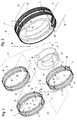
- Fig. 1 shows the essential components of an inventive inductive angle measuring device 1 in perspective Exploded view.
- the angle measuring device 1 consists of two measuring coils 2 and 3, a transmitter coil 35 and from a measuring body 45.
- the two measuring coils 2 and 3 are identical and each have a first coil ring 5 or 6 and a second Coil ring 7 or 8.
- the coil rings 5, 6, 7 and 8 are each in two with respect to a common one Coil axis 42 diametrically opposite coil sections divided.
- the first coil ring 5 has the Measuring coil 2 a first coil section 10 and one second coil section 11, which over a Extend the central angle in the circumferential direction over approximately 180 °.
- the second coil ring 7 of the measuring coil 2 has also a first coil section 12 and one second coil section 13, which is also diametrically opposite and which are in the circumferential direction each over a central angle of approximately 180 ° extend.
- the first coil ring 6 is the measuring coil 3 also in a first coil section 14 and in one second coil section 15 divided.
- the second Coil ring 8 of the measuring coil 3 also has a first Coil section 16 and a second coil section 17 on, with the coil sections 14 and 15 of the coil ring 6 and the coil sections 16 and 17 of the coil ring 8 are also diametrically opposite and each over a central angle in the circumferential direction extend from approximately 180 °.
- the windings of the respective first coil ring 5 or 6 and the respective second coil ring 7 or 8 cross diametrically opposite in two intersection areas 18 and 19 or 20 and 21 such that the respective first coil section 10 or 14 of the respective first Coil ring 5 or 6 in the axial direction of the coil axis 9 behind the respective first coil section 12 or 16 of the respective second coil ring 7 or 8. Accordingly are the respective second coil sections 11 and 15 of the respective first coil ring 5 or 6 axially in front of the respective second coil section 13 or 17 of the second coil ring 7 or 8.
- the two coil rings 5 and 7 of the first measuring coil 2 are in the crossing area 19 of the windings of their two coil rings 5 and 7 connected to each other as by the electrical connecting web 22 indicated in Fig. 1 is.
- the connecting lines are also in this intersection area 19 23 and 24 provided on which the measurement signal of Measuring coil 2 is removable. It is understood that the connecting lines 23 and 24 not necessarily in the peripheral area of the intersection area 19 must be arranged. However, it is advantageous if both connecting lines 23 and 24 arranged in the same circumferential area of the measuring coil 2 are so that both coil rings 5 and 7 are the same Have coil geometry and unaffected with the same alternating magnetic field, the same output voltage is induced in them. Are both coil rings identically designed, so is that on the connecting lines 23 and 24 removable measuring voltage in the unaffected State of the measuring coil 2 is zero, since the in the Coil sections 10, 11 and 12, 13 of the oppositely wound Coil rings 5 and 7 induced in this The opposite voltages are equal.
- a connecting web 26 is provided, via which the two coil rings 6 and 8 are electrically coupled together.
- two connecting lines 28 and 29 are provided, via which a corresponding measurement signal on the measuring coil 3 is removable.
- the two measuring coils 2 and 3 arranged coaxially to each other and at an angle offset from each other by 90 ° in the circumferential direction. This means, that the intersection areas 18 and 19 of the measuring coil 2 approximately in a vertical plane and offset by 90 ° the crossing areas 20 and 21 of the measuring coil 3 are arranged approximately in a horizontal plane are.
- the measuring body 45 By mutually influencing the inductances of the Measuring coils 2 and 3 or the coil sections 10, 11, 12, 13 and 14, 15, 16, 17 of the coil rings 5, 7 and 6, 8 of the two measuring coils 2 and 3 by one, as exemplified in Fig. 1 shown measuring body 45, however, change the induced voltages in the coil sections 10, 11, 12, 13 and 14, 15, 16, 17 of the coil rings 5 and 7 or 6 and 8, so that on the connecting lines 23, 24 and 28, 29 corresponding voltage signals in positive or negative direction are removable.
- the measuring body 45 made of a metallic Material formed which is a positive or negative electromagnetic coupling and therefore also one accordingly influencing the inductances.
- the measuring body 45 has an outer, approximately semi-cylindrical cylinder section 46 which extends over a circumferential angle of approximately 180 °.
- This cylinder section 46 is diametrically opposed to a cylinder wall section 47, which also extends over 180 ° in the circumferential direction, and whose outer diameter r is smaller than the outer diameter R of the cylinder section 46.
- the two Measuring coils 2, 3 with their coil sections 10, 11, 12, 13 and 14, 15, 16, 17 are arranged so that their front coil portions 11, 12 and 15, 16 or their rear coil sections 10, 13 and 14, 17 congruent in the axial direction are.
- the measuring coils 2, 3 can be different Have diameters so that they are mutual can be pushed into each other, or they can also be wrapped in one another during their manufacture.
- the cylinder section 46 has a substantially smaller radial distance from the measuring coils 2 and 3 or from their coil rings 5 and 7 or 6 and 8, so that the inductances of the coil rings 5 and 7 or 6 and 8, but especially their coil sections 10, 11 and 12, 13 or 14, 15 and 16, 17, depending on the angular position of the cylinder section 46 relative to these coil sections 10 to 17, induce different measuring voltages in these .
- the cylinder section 46 can extend in the axial direction at least over an axial length in the direction of the coil axis 42, which corresponds to the width B of a coil ring 5, 6, 7 or 8. In the present exemplary embodiment, however, the cylinder section 46 extends over the entire axial length of the measuring coils 2, 3 and the transmitting coil 35.
- An increase in this Tension of the coil section 11 becomes, for example by inductive coupling through the cylinder section 46 reached when the cylinder section 46, for example is formed from a ferromagnetic material.
- a negative coupling or damping is in use a non-magnetic metallic material for the Cylinder section 46 reached, so that in this case in the coil section 11 at the rotational position shown of the cylinder section 46 the induced voltage less than in the unaffected coil section 12.
- a differential voltage measurable which can be further evaluated as a measurement signal is.
- the measuring voltage is the same Zero since the coil sections 10, 11 and 12, 13 induced voltages are of equal magnitude and thus equalize each other.
- the measuring coil 3 is also used to measure the angle of rotation and, for example, its coil sections 14, 15, 16 and 17 are axially congruent with the coil sections 10, 11, 12 and 13 of the measuring coil 2 or their coil rings 5 and 7, one can be arranged in this identical measurement signal can be induced and removed.
- This measuring signal is, however, 90 o out of phase with the measuring signal of the measuring coil 2, since the measuring coil 3 is arranged with its crossing regions 20 and 21 rotated in the circumferential direction by 90 ° to the crossing regions 18 and 19 of the measuring coil 2.
- the measuring body 45 thus acts with its cylinder section 45 in the same way on the measuring coil 3.
- the two measuring coils 2 and 3 are advantageously of identical design, so that the detachable measuring signals are identical in their amplitude.
- two measurement signals are available, which are phase-shifted by 90 ° to each other, for measuring the angle of rotation of the angle of rotation of the measuring body 45, so that the angle of rotation position and also the direction of rotation of the measuring body 45 can be measured reliably.
- the transmitter coil 35 To generate the alternating magnetic field is, as already mentioned in the angle measuring device 1/1 the transmitter coil 35 provided.
- the transmission coil 35 in two coil rings 36 and 37 divided, which are wound in opposite directions.
- the coil rings 36 and 37 of the transmitter coil 35 are made of a single Coil wire wound, which in the drawing in lower, deepest area 39 has a turning bridge 38, which electrically connects the two coil rings 36 and 37 to one another connects.
- Also in this deepest area 39 are two connecting lines 40 and 41 of the transmitter coil 35 provided, in which the required AC voltage can be applied to generate the alternating magnetic field is.
- the two coil rings are 36 and 37 in the axial direction of the coil axis 42 in a distance in a row.
- This causes through the coil rings 36 and 37 due to their opposing Direction of winding also opposite magnetic Alternating fields with a phase shift of 180 ° are generated become.
- This transmitter coil 35 becomes such in operation either wrapped in the two measuring coils 2 and 3 or surrounds these measuring coils 2 and 3 such that they with her in the drawing front coil ring 36 in the axial Area of the coil sections 11 and 12 of the coil ring 5 or 7 and in the region of the coil sections 15 and 16 of the Coil rings 6 and 8 is arranged.
- the distance between the coil rings 36 and 37 of the transmitter coil 35 in the axial direction is the distance between the axially one behind the other Coil sections 12 and 10 or 11 and 13 or 16 and 14 or 15 and 17 of the coil rings 5 and 7 or 6 and 8 matched so that the axially behind in the drawing lying coil ring 37 of the transmitter coil 35 approximately in the axial Area of the rear coil sections 14 and 17 of the measuring coil 3 or 10 and 13 of the measuring coil 2.
- the measuring body 45 is provided in the angle measuring device 1/1 for inducing different measuring voltages.
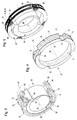
- Fig. 2 shows the assembled state of the angle measuring device 1/1 in a basic arrangement.
- Fig. 3 shows a measuring coil 50, the basic structure corresponds to the measuring coil 2 from FIGS. 1 and 2.
- the measuring coil 50 is designed as a so-called “air coil” and maintains its stability through a so-called “baking lacquer technique”.
- the measuring coil 50 also has a first coil ring 51 and a second coil ring 52, each in a first coil section 53 or 54 and a second Coil section 55 and 56 are divided.
- the cylinder section 64 or the entire measuring body 63 can a positive feedback or negative feedback material be, with the feedback material as a die Inductance reinforcing material is a ferromagnetic Metal is provided.
- negative feedback material or damping material can on the other hand for the Measuring body 63 is a non-magnetic metallic material be provided.
- the cylinder section 64 also as separate components on a cylinder can be applied, in which case the Cylinder made of a neutral material with respect to its Influencing the inductors is formed.
- the measurement signal the "air coil” 50 becomes the measuring coil accordingly 2 from Fig. 1 on the connecting lines 60 and 61 removed.
- Fig. 3 was on the representation of a second Measuring coil and the transmitter coil for reasons of clarity waived.
- the second measuring coil and the Transmitter coil could e.g. in the Diameter may be larger than that shown first measuring coil and enclose it.
- Fig. 4 shows a special, approximately ring-shaped Coil body 67, on which, for example 1 and 2 in a simple manner is windable.
- the coil former 67 has a winding cylinder 68 on which in the axial direction of its Cylinder axis 69 at its ends by a radial extended web wall 70 or 71 is limited.
- This two web walls 70 and 71 each delimit on the outside the winding area in which on the bobbin 67 corresponding windings according to the basic diagram 1 can be wound up.
- a radial separator 72 is provided by which the winding cylinder 68 axially in a front and a rear winding area 73 and 74 is divided.
- the separating web 72 is interrupted in the circumferential direction, so that four each offset by 90 ° to each other Junction areas 75, 76, 77 and 78 are formed become. Through these intersection areas 75 to 78 are on the coil body 67 in a simple manner electromagnetic Induction coils with winding geometries of the ones to be wound Coils according to the three coils from FIG. 1 can be accommodated.
- Fig. 5 shows the bobbin 67 with finished wound Coils 79, 80 and 81, these coils 79, 80 and 81 are wound into each other in such a way that from the illustration 5 the individual coils can no longer be recognized individually are.
- eyelets 82, 83, 84 and 85 are provided which connecting elements to the according to necessary connection lines or measuring lines, as they are indicated in Fig. 1 represent.
- the corresponding one of the measuring coil 3 Measuring coil in Fig. 5 around a vertical axis Must be turned 180 ° so that the eyelets 84 and 85 in the front portion of the bobbin shown 67 are arranged.
- FIG. 6 is the block diagram of a differential transformer system in principle with a transmitter coil 105 and two Measuring coils 87 and 91 shown.
- the transmitter coil 105 is for generating the alternating magnetic field intended.
- the two measuring coils 87 and 91 can different in diameter be so that they are not directly wrapped in each other, but have a radial distance from each other.
- the two measuring coils 87 and 91 larger in diameter than that Transmitter coil 105, with all coils 87, 91 and 105 the measuring body 45 from FIG. 1 is arranged.
- intersection areas 88 and 89 of the first measuring coil 87 in a horizontal plane 90 these intersection areas 88 and 89 diametrically opposite.
- the second measuring coil 91 shows its two crossing areas 92 and 93 in a vertical plane rotated by 90 ° to the horizontal plane 90 94, the two intersection areas 92 and 93 are also diametrically opposed.
- 6 is a carrier frequency generator 95 recognizable by which the transmitter coil 105 over the two Connection lines 96, 97 with a carrier frequency voltage is applied so that an alternating magnetic field is generated by the transmitter coil 105.
- This Alternating field passes through the two measuring coils 87 and 91, see above that at their ends through the connecting lines 106, 107 or 108, 109 a corresponding measuring voltage can be removed is, which by a respective demodulator 100 or 102 can be demodulated for further processing.
- the Measuring voltages are directly from the winding ends in the crossing areas 88 and 93 of the two measuring coils 87 and 91 removed.
- 6 is the measuring body 45 in shown an angular position in which the end edges of the cylinder section 46 at a set angle ⁇ is arranged from 45 ° to the horizontal 90.
- the curves of the individual voltages that is to say the carrier frequency voltage 110 of the transmitter coil 105 and the two measurement signals or measurement voltages 111 and 112 of the two coils 87 and 91, are shown in FIG. 7.
- a rotation angle of 0 ° for example, no measuring voltage is induced in the first measuring coil 87.
- This 0 ° position would be reached, for example, if the measuring body 45 from FIG. 6 with the ends of its cylinder sections 46 is in the vertical plane 94.
- a maximum measuring voltage 112 is induced in the second measuring coil 91.
- the measuring voltage 111 of the first measuring coil 87 increases to its maximum, while the measuring voltage 112 of the second measuring coil 91 drops to zero.
- the measuring voltage of the first measuring coil 87 decreases to zero, while the measuring voltage 112 of the second measuring coil 91 increases to its maximum value.
- a phase shift of the measuring signal by 90 ° occurs, so that the measuring voltage 112 has a negative sign with respect to the carrier frequency voltage 110 from the angle of rotation 90 ° to the angle of rotation 180 ° or ⁇ , so to speak.
- the measuring voltage 111 of the first measuring coil 87 when the measuring body 45 passes through the 180 ° angular position, a phase shift of 90 ° also occurs, so that when the measuring body 45 is rotated further to 270 °, the measurement signal also grows to a maximum value , but has a negative sign with respect to the carrier frequency voltage 110.
- the second measuring signal of the second measuring coil 91 is reduced to zero again.
- a further phase shift of 90 ° occurs in this second measuring signal 112, so that 360 ° and in the position 2 112 ⁇ , upon further rotation of the measuring body 45, the measuring voltage again increases, but now has a positive sign with respect to the carrier frequency voltage 110.
- the first measuring voltage 111 of the first measuring coil is again reduced to zero. From this signal curve of the measuring voltages 111 and 112, the angle of rotation of the measuring body 45 and its direction of rotation can be determined in a simple manner by demodulating the two measuring signals. From the 90 ° phase shift of the measuring signal 111 of the measuring coil 87 occurring after 180 ° and 360 ° respectively or from the 90 ° phase shift of the measuring signal at 90 ° and 270 °, the direction of rotation of the Measuring body 45 can be determined in a simple manner.
- phase shifts occur due to the geometrical structure of the two measuring coils 87 and 91 after every half revolution by 180 ° of the measuring body 45, with the second measuring coil 91 correspondingly having to be offset by 90 ° in the circumferential direction from the first measuring coil 87, and thus whose phase shifts occur delayed by 90 °.
- the two measurement signals 111 and 112 are identical Coil geometry of both measuring coils 87 and 91, in their The course over time is identical and 90 ° in the direction of rotation of the measuring body 45 shifted.
- the inductive angle measuring device becomes a non-contact encoder for position reporting a measuring body by generating an analog signal via provided a rotation angle of 360 °.
- the coil arrangement is on the one hand on a coil former or also possible as an air coil in baked enamel technology.
- the individual coils can be used in a rotary winding technique be produced in one operation so that extremely low manufacturing costs with optimal inductive relationships of the individual coils to each other surrender.
- the angle measuring device according to the invention is ideal for a hollow shaft arrangement or for an axis application suitable, in particular with a hollow shaft arrangement the measuring body, for example, in the inner wall of the Hollow shaft can be arranged and the actual coil system arranged within this rotating measuring body can be. Also, like this can also be seen from the drawing figures it becomes clear the complete coil arrangement, in particular when wound as a unit on a bobbin is already one at any point existing shaft can be used because it is in axial Direction with appropriate dimensioning in diameter pushed onto the shaft at the intended location can be.
- the angle measuring device according to the invention is therefore not limited to use at one shaft end, as is the case for example with those described at the beginning Resolvers is the case.
- the material of the measuring body as Swivel anchor with an arch part extending approximately 180 ° or cylinder section can provide signal amplification in the individual coil sections or also one Attenuation of the signal in the individual coil sections can be achieved so that also with respect to the measuring body variable configuration is possible.
- this measuring body does not have to have its own storage, for example be arranged on each drive shaft can.
- the coil arrangement can also have its own housing, for example 3, be formed, which further increases the variability of the area of application becomes.
- the Carrier frequency can be chosen extremely high, resulting in a extremely high sensor speed with high speed Sensitivity to the change in the angle of rotation of the Measuring body is reached.
- the signal evaluation can be done with commercially available inexpensive integrated circuits be carried out, which in turn only a small Cost expenditure when using the invention Angle measuring device is reached. Because the magnetic Coupling between the individual measuring coils and the transmitter coil extremely large due to the integrated windings is, only an extremely low energy consumption of the entire measuring system.
Applications Claiming Priority (2)
| Application Number | Priority Date | Filing Date | Title |
|---|---|---|---|
| DE19800380 | 1998-01-08 | ||
| DE1998100380 DE19800380C2 (de) | 1998-01-08 | 1998-01-08 | Induktive Winkelmeßvorrichtung |
Publications (2)
| Publication Number | Publication Date |
|---|---|
| EP0932018A2 true EP0932018A2 (fr) | 1999-07-28 |
| EP0932018A3 EP0932018A3 (fr) | 2000-09-20 |
Family
ID=7854127
Family Applications (1)
| Application Number | Title | Priority Date | Filing Date |
|---|---|---|---|
| EP99100063A Withdrawn EP0932018A3 (fr) | 1998-01-08 | 1999-01-05 | Dispositif inductif pour mesurer des angles |
Country Status (2)
| Country | Link |
|---|---|
| EP (1) | EP0932018A3 (fr) |
| DE (1) | DE19800380C2 (fr) |
Cited By (2)
| Publication number | Priority date | Publication date | Assignee | Title |
|---|---|---|---|---|
| EP1524502A2 (fr) * | 2003-10-17 | 2005-04-20 | Minebea Co. Ltd. | Capteur de rotation en tandem |
| RU2608200C2 (ru) * | 2012-02-24 | 2017-01-17 | Бомбардир Транспортацион Гмбх | Шарнир для рельсовых транспортных средств или модулей рельсового транспортного средства с датчиком угла |
Families Citing this family (3)
| Publication number | Priority date | Publication date | Assignee | Title |
|---|---|---|---|---|
| DE102018108019B4 (de) | 2017-05-12 | 2021-10-14 | Rheinmetall Air Defence Ag | Messanordnung zur Messung einer Drehlage und/oder einer Drehzahl einer Kurbelwelle |
| WO2019166258A1 (fr) * | 2018-03-02 | 2019-09-06 | Admotec Precision Ag | Anneau de rotor |
| DE202018102239U1 (de) | 2018-04-21 | 2019-05-23 | Igus Gmbh | Energieführungskette mit Verschleißerkennung |
Citations (3)
| Publication number | Priority date | Publication date | Assignee | Title |
|---|---|---|---|---|
| DE4243022A1 (de) * | 1992-12-18 | 1994-06-23 | Bosch Gmbh Robert | Meßeinrichtung zur Bestimmung eines Drehwinkels |
| WO1994014027A1 (fr) * | 1992-12-12 | 1994-06-23 | Penny & Giles Blackwood Limited | Transducteur rotatif |
| EP0664441A2 (fr) * | 1991-04-26 | 1995-07-26 | Walter Dr. Mehnert | Capteur inductif de position |
Family Cites Families (1)
| Publication number | Priority date | Publication date | Assignee | Title |
|---|---|---|---|---|
| DE4335701C2 (de) * | 1993-10-20 | 1996-04-04 | Ifm Electronic Gmbh | Induktive Winkelmeßeinrichtung |
-
1998
- 1998-01-08 DE DE1998100380 patent/DE19800380C2/de not_active Expired - Fee Related
-
1999
- 1999-01-05 EP EP99100063A patent/EP0932018A3/fr not_active Withdrawn
Patent Citations (3)
| Publication number | Priority date | Publication date | Assignee | Title |
|---|---|---|---|---|
| EP0664441A2 (fr) * | 1991-04-26 | 1995-07-26 | Walter Dr. Mehnert | Capteur inductif de position |
| WO1994014027A1 (fr) * | 1992-12-12 | 1994-06-23 | Penny & Giles Blackwood Limited | Transducteur rotatif |
| DE4243022A1 (de) * | 1992-12-18 | 1994-06-23 | Bosch Gmbh Robert | Meßeinrichtung zur Bestimmung eines Drehwinkels |
Cited By (4)
| Publication number | Priority date | Publication date | Assignee | Title |
|---|---|---|---|---|
| EP1524502A2 (fr) * | 2003-10-17 | 2005-04-20 | Minebea Co. Ltd. | Capteur de rotation en tandem |
| EP1524502A3 (fr) * | 2003-10-17 | 2006-01-18 | Minebea Co. Ltd. | Capteur de rotation en tandem |
| US7279890B2 (en) | 2003-10-17 | 2007-10-09 | Minebea Co., Ltd. | Tandem rotation detector for high precision detection |
| RU2608200C2 (ru) * | 2012-02-24 | 2017-01-17 | Бомбардир Транспортацион Гмбх | Шарнир для рельсовых транспортных средств или модулей рельсового транспортного средства с датчиком угла |
Also Published As
| Publication number | Publication date |
|---|---|
| DE19800380C2 (de) | 2000-03-02 |
| EP0932018A3 (fr) | 2000-09-20 |
| DE19800380A1 (de) | 1999-07-15 |
Similar Documents
| Publication | Publication Date | Title |
|---|---|---|
| DE2951148C2 (de) | Meßeinrichtung für einen Drehwinkel und/oder ein Drehoment | |
| EP0334854B1 (fr) | Dispositif de mesure d'une rotation angulaire et ou d'une vitesse de rotation | |
| EP1902288A1 (fr) | Dispositif capteur pour saisir un angle differentiel | |
| EP0510367B1 (fr) | Capteur inductif de position | |
| EP2023093A2 (fr) | Encodeur et son procédé de fonctionnement | |
| DE102015220615A1 (de) | Drehwinkelsensor | |
| DE2305384C2 (de) | Anordnung zur Bestimmung der Windelstellung und Drehzahl | |
| DE60215414T2 (de) | Apparat zur Erfassung einer relativen Winkelpositionsänderung | |
| EP0528199B1 (fr) | Transducteur pour produire par induction un signal de mesure | |
| EP0108950B1 (fr) | Dispositif pour déterminer la vitesse de rotation d'une pièce tournante | |
| WO2001086233A1 (fr) | Transducteur de mesure inductif | |
| DE69824059T2 (de) | Resolver mit Verlustfluxabsorber | |
| DE2216091A1 (de) | Vorrichtung zur beruehrungslosen temperaturmessung an einem sich bewegenden gegenstand | |
| DE2923644A1 (de) | Positionsfuehler | |
| DE102015208837B4 (de) | Sensoranordnung mit einem Winkelsensor sowie Wälzlageranordnung mit Sensoranordnung | |
| EP0425529B1 (fr) | Dispositif de mesure pour la determination d'un ecart angulaire | |
| EP0535181B1 (fr) | Resolveur | |
| DE102018211179A1 (de) | Resolver und Motor | |
| EP0932018A2 (fr) | Dispositif inductif pour mesurer des angles | |
| DE102005061347A1 (de) | Anordnung zur Messung des absoluten Drehwinkels einer Welle | |
| DE19646056C2 (de) | Vorrichtung zum Messen der Drehzahl eines um eine Drehachse rotierenden Körpers | |
| EP0512282B1 (fr) | Capteur d'angle pour déterminer sans contact la rotation d'un arbre | |
| DE4021637A1 (de) | Induktiver stellungsgeber | |
| DE1927355B2 (de) | Elektromechanischer wandler | |
| DE10256321A1 (de) | Vorrichtung zum Bestimmen eines auf eine Welle ausgeübten Drehmoments |
Legal Events
| Date | Code | Title | Description |
|---|---|---|---|
| PUAI | Public reference made under article 153(3) epc to a published international application that has entered the european phase |
Free format text: ORIGINAL CODE: 0009012 |
|
| AK | Designated contracting states |
Kind code of ref document: A2 Designated state(s): AT BE CH ES FR GB IT LI LU NL PT SE |
|
| AX | Request for extension of the european patent |
Free format text: AL;LT;LV;MK;RO;SI |
|
| PUAL | Search report despatched |
Free format text: ORIGINAL CODE: 0009013 |
|
| AK | Designated contracting states |
Kind code of ref document: A3 Designated state(s): AT BE CH CY DE DK ES FI FR GB GR IE IT LI LU MC NL PT SE |
|
| AX | Request for extension of the european patent |
Free format text: AL;LT;LV;MK;RO;SI |
|
| 17P | Request for examination filed |
Effective date: 20001017 |
|
| AKX | Designation fees paid |
Free format text: AT BE CH ES FR GB IT LI LU NL PT SE |
|
| REG | Reference to a national code |
Ref country code: DE Ref legal event code: 8566 |
|
| GRAP | Despatch of communication of intention to grant a patent |
Free format text: ORIGINAL CODE: EPIDOSNIGR1 |
|
| STAA | Information on the status of an ep patent application or granted ep patent |
Free format text: STATUS: THE APPLICATION HAS BEEN WITHDRAWN |
|
| 18W | Application withdrawn |
Effective date: 20031004 |