EP0932018A2 - Inductive angle measuring device - Google Patents
Inductive angle measuring device Download PDFInfo
- Publication number
- EP0932018A2 EP0932018A2 EP99100063A EP99100063A EP0932018A2 EP 0932018 A2 EP0932018 A2 EP 0932018A2 EP 99100063 A EP99100063 A EP 99100063A EP 99100063 A EP99100063 A EP 99100063A EP 0932018 A2 EP0932018 A2 EP 0932018A2
- Authority
- EP
- European Patent Office
- Prior art keywords
- coil
- measuring
- coils
- ring
- section
- Prior art date
- Legal status (The legal status is an assumption and is not a legal conclusion. Google has not performed a legal analysis and makes no representation as to the accuracy of the status listed.)
- Withdrawn
Links
Images

Classifications
-
- G—PHYSICS
- G01—MEASURING; TESTING
- G01D—MEASURING NOT SPECIALLY ADAPTED FOR A SPECIFIC VARIABLE; ARRANGEMENTS FOR MEASURING TWO OR MORE VARIABLES NOT COVERED IN A SINGLE OTHER SUBCLASS; TARIFF METERING APPARATUS; MEASURING OR TESTING NOT OTHERWISE PROVIDED FOR
- G01D5/00—Mechanical means for transferring the output of a sensing member; Means for converting the output of a sensing member to another variable where the form or nature of the sensing member does not constrain the means for converting; Transducers not specially adapted for a specific variable
- G01D5/12—Mechanical means for transferring the output of a sensing member; Means for converting the output of a sensing member to another variable where the form or nature of the sensing member does not constrain the means for converting; Transducers not specially adapted for a specific variable using electric or magnetic means
- G01D5/14—Mechanical means for transferring the output of a sensing member; Means for converting the output of a sensing member to another variable where the form or nature of the sensing member does not constrain the means for converting; Transducers not specially adapted for a specific variable using electric or magnetic means influencing the magnitude of a current or voltage
- G01D5/20—Mechanical means for transferring the output of a sensing member; Means for converting the output of a sensing member to another variable where the form or nature of the sensing member does not constrain the means for converting; Transducers not specially adapted for a specific variable using electric or magnetic means influencing the magnitude of a current or voltage by varying inductance, e.g. by a movable armature
- G01D5/204—Mechanical means for transferring the output of a sensing member; Means for converting the output of a sensing member to another variable where the form or nature of the sensing member does not constrain the means for converting; Transducers not specially adapted for a specific variable using electric or magnetic means influencing the magnitude of a current or voltage by varying inductance, e.g. by a movable armature by influencing the mutual induction between two or more coils
- G01D5/2046—Mechanical means for transferring the output of a sensing member; Means for converting the output of a sensing member to another variable where the form or nature of the sensing member does not constrain the means for converting; Transducers not specially adapted for a specific variable using electric or magnetic means influencing the magnitude of a current or voltage by varying inductance, e.g. by a movable armature by influencing the mutual induction between two or more coils by a movable ferromagnetic element, e.g. a core
Definitions
- the invention relates to an inductive angle measuring device with at least one electromagnetic measuring coil, into which a measuring voltage is induced by at least one alternating magnetic field, and with a rotatingly drivable measuring body influencing the inductance and the measuring voltage of the measuring coil as a function of its angular position relative to the measuring coil, with at least one measuring body which are over a central angle of about 180 o extending cylinder portion, wherein the measuring coil comprises a first and a second coil ring is formed coaxial with each other and are each divided into a first and second coil portions, which oppose each other diametrically, and wherein the windings cross over of the two coil rings such that the first coil section of the first coil ring is axially offset in an axial direction of the coil axis in front of the first coil section of the second coil ring and the second coil section of the first Coil ring is arranged axially offset in the same axial direction behind the second coil section of the second coil ring.
- Angle measuring devices are known, which at least have an electromagnetic measuring coil in which a measuring voltage induced by an alternating magnetic field becomes.
- Such inductive angle measuring devices enable the simple electrical detection and measurement mechanical quantities by dividing these mechanical quantities into an analog voltage signal can be converted.
- For angle measurement becomes one in the inductive range the measuring body arranged rotatingly driven, so that depending on the angular position of the Measuring body relative to the measuring coil, its inductance and so that their measuring voltage is influenced.
- a measuring body serve essentially measuring cylinders, their peripheral surface with an approximately semi-cylindrical design a special material that influences the inductance existing material formed body section is provided.
- the known angle measuring devices can formed from two coils or coil sections be interconnected in an inductive half-bridge are or they work on the principle of a differential transformer.
- Such an inductive half-bridge consists of two in series switched coils, which with an AC voltage of 10 kHz, for example. Through this AC voltage becomes a corresponding one in the coils Alternating current I caused by which a magnetic Alternating flow is generated.
- This alternating flow induces according to the law of induction, a self-induction voltage, which in both coils with the same training the coils are the same size.
- these two coils in the peripheral area of a rotationally driven Arranged measuring body and become the inductors of the two coils during the rotating movement of the Measuring body influenced differently one after the other, so arises depending on the angle of rotation of the measuring body and voltage change proportional to this angle, which removable in the connection area between the two coils is.
- This voltage change can be from a demodulator converted into a corresponding DC voltage signal which are then proportionally proportional to Angle change or the angle of rotation of the measuring body. In this way, the angle of rotation can be easily of a measuring body using a voltage signal.
- the Output signals are stepless and have a constant Course.
- Inductive angle measuring devices which designed according to the principle of the inductive half-bridge are used to measure angles with a linear Measuring range of +/- 45 °. This means that such after an inductive half-bridge designed angle measuring devices for a rotation angle measurement over an angular range of 360 ° are not suitable or only suitable to a limited extent.
- Such angular measurements over an angular range of 360 ° and more can, however, be measured by inductive angle measuring devices which operate according to the differential transformer principle.
- angle measuring devices for example, which are referred to as so-called “resolvers”, have become known (prospectus Baumer electric, TTW 4/96 No. 800164).
- This company publication describes a miniature resolver designed as a purely passive angle measuring system, which is actually a transformer with an angle-dependent, electromagnetic coupling.
- This resolver has a purely passive rotor without coils.
- a fixed primary coil is powered by an AC voltage. It creates a homogeneous magnetic alternating field inside.
- Stationary receiver coils or measuring coils which are penetrated by this homogeneous, alternating magnetic field, are located as receivers within this transmitter coil. Consequently, a voltage to be measured is induced in these measuring coils arranged inside the transmitting coil, which voltage is dependent on the inductive coupling between the transmitting coil and the measuring coils. Without further influencing this system, voltages of the same size and, depending on the winding direction of the individual coils, with different or the same sign are generated in the measuring coils. Furthermore, a rotor is arranged in the transmitting coil, which has a ferromagnetic part which rotates all round with the rotor and which successively influences the measuring coils arranged one after the other in the circumferential direction.
- This ferromagnetic part of the rotor changes the alternating electromagnetic field inside the transmitter coil so that different voltages are induced in the measuring coils depending on the angle of rotation of the rotor.
- Four measuring coils are provided, which are assigned to one another in pairs, diametrically opposite one another. These paired measuring coils are wound in opposite directions and run with their coil axis parallel to the coil axis of the transmitter coil, which in turn is arranged parallel and concentric to the axis of rotation of the rotor. Each pair of measuring coils generates a measuring voltage that is dependent on the angle of rotation, so that a total angle of 360 ° can be detected by this measuring voltage of each pair of coils. Since the measuring coils are arranged in pairs circumferentially offset by 90 o to each other, both the rotor angle and the direction of rotation of the rotor can be determined from the two measuring voltages phase-shifted by 90 °.
- This known resolver is characterized by a restricted inductive coupling between the transmitter coil and the measuring coils, since the transmitter coil outside of the actual Measuring coils is arranged and thus the electromagnetic Coupling is not optimal. Furthermore is also due to the provided individual measuring coils, which are diametrically opposed in pairs a complicated one mechanical construction necessary. Can too such resolvers not according to the structure described any size can be made, as with increasing Size of the resolver the inductive coupling between the transmitter coil and the measuring coils deteriorated and thus the measuring accuracy of such an inductive angle measuring device becomes inaccurate with increasing size. In addition, such a resolver increases in size more sensitive to external interference.
- an angle measuring device which has a rotor which has two approximately semicircular Has cylinder sections. These cylinder sections are in the axial direction of the axis of rotation of the rotor arranged axially one behind the other and in the circumferential direction offset from each other by 180 °.
- the rotor is assigned a measuring coil, which consists of two coil rings is formed and arranged stationary, coaxial to the rotor is.
- the two coil rings are roughly two each Coil sections extending over a central angle of 180 ° divided, the respective first coil section a coil ring axially in the area of the front Cylinder section and the respective second coil section a coil ring axially in the area of the rear Cylinder section of the rotor is arranged.
- the so step-wound coil rings cross each other and stand with their coil sections with both cylinder sections of the rotor during a full revolution of the rotor in operative connection.
- This coil arrangement are intended to shift the rotor in all directions be compensated for relative to the measuring coil. Because with this known angle measuring device no transmitter coil is provided but the measuring coils themselves with the carrier frequency is applied to build up a magnetic field, Such angle measuring devices can also be made larger become.
- the invention has for its object a to provide inductive angle measuring device, in which to achieve the largest possible linear Measuring range an optimal inductive coupling between the magnetic alternating field and the one or more used Measuring coils essentially independent of the size of the Angle measuring device is reached, at the same time a simple and inexpensive construction guaranteed should be.
- the task is performed in conjunction with the characteristics of the Preamble of claim 1 according to the invention solved that the coil rings of the measuring coil wound in opposite directions are, and that a coaxially arranged to the measuring coil Transmitter coil is provided which is opposed to two wound coil rings, which is such are arranged axially one behind the other that the first Coil ring axially in the area of the front coil sections and the second coil ring axially in the area of rear coil sections is arranged.
- the configuration according to the invention enables a contactless, inductive angle measuring device available with which the angular position of a measuring body by generating an analog signal over an angle of rotation of 360 ° can be determined.
- the angle measuring device according to the invention is characterized by a simple mechanical and a simple structure of the electronic Evaluation device. Furthermore, it becomes independent of the size of the angle measuring device an optimal inductive Coupling between the transmitter coil and the measuring coil achieved because this is all around in immediate spatial Proximity.
- the measuring coil has a first and a second Coil ring, which are wound in opposite directions and are arranged coaxially to each other.
- Each of the coil rings is in a first and a second coil section divided, which each with respect to the Coil axis are diametrically opposite.
- These windings of the two coil rings cross each other, so that the first Coil section of the first coil ring in an axial direction the coil axis of the measuring coil axially offset from the lies first coil section of the second coil ring.
- the second coil section of the first Coil ring axially offset in the same axial direction behind the second coil section of the second coil ring. This means that the two coil rings or cross their windings diametrically opposite one another.
- the intended measuring body is concentric to the coil axis arranged the measuring coil and has on its outer surface a cylinder section, which extends over a Central angle extends from about 180 °.
- This cylinder section extends in the axial direction of the coil axis at least across the width of one of the coil sections, so that when it rotates depending on the Angle of rotation of the measuring body alternately, for example in the axially front area lying coil sections two coil rings are affected, provided the cylinder section of the measuring body arranged in this axial area is.
- the alternating magnetic field is generated by a transmitter coil generated, which with a corresponding AC voltage and thus applied to a corresponding alternating current becomes.
- This alternating current makes the required magnetic Alternating field generated, through which in the measuring coil a corresponding voltage is induced.
- the transmitter coil is arranged coaxially to the measuring coil and exists from two oppositely wound coil rings, which lying axially one behind the other in the direction of the coil axis are arranged.
- the first coil ring is located here the transmitter coil axially in the area of the front coil sections the coil rings of the measuring coil and the second coil ring the transmitter coil axially in the area of the rear coil sections.
- the measuring body is the inductance of the Area of action of the measuring body lying coil sections depending on the rotation angle of the measuring body or its cylinder section alternately influenced, so that the induced output voltages of the measuring coil in dependence from the angle of rotation of the cylinder section of the measuring body is changed.
- the cylinder section of the Measuring body preferably over the entire width of the adjacent Coil sections, thereby reinforcing the Influencing the inductance of the coil sections of the two coil rings is effected.
- second measuring coil can be provided in the circumferential direction with their coil sections offset by 90 ° to the first Measuring coil is arranged.
- the measuring body can also have a semi-cylindrical cylinder section, of the length of a coil ring or also over the entire length of both in a row Coil rings extends.
- the two measuring coils can at least be small in size be wrapped in areas.
- the inductive coupling is thereby significant improved that the windings of the transmitter coil with the windings of the two measuring coils in some areas are wrapped in each other so that an optimal magnetic Coupling between the individual coil sections and the transmitter coil is reached.
- the individual Coils or the coils wound into one another according to Claim 8 can also be designed as a so-called air coils.
- the measuring coils and the transmitter coil in their diameter can also be designed differently can, so that they can be pushed into each other and thus an extremely good electromagnetic coupling between the individual coil sections of the measuring coil and the coil rings of the transmitter coil is reached.
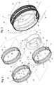
- Fig. 1 shows the essential components of an inventive inductive angle measuring device 1 in perspective Exploded view.
- the angle measuring device 1 consists of two measuring coils 2 and 3, a transmitter coil 35 and from a measuring body 45.
- the two measuring coils 2 and 3 are identical and each have a first coil ring 5 or 6 and a second Coil ring 7 or 8.
- the coil rings 5, 6, 7 and 8 are each in two with respect to a common one Coil axis 42 diametrically opposite coil sections divided.
- the first coil ring 5 has the Measuring coil 2 a first coil section 10 and one second coil section 11, which over a Extend the central angle in the circumferential direction over approximately 180 °.
- the second coil ring 7 of the measuring coil 2 has also a first coil section 12 and one second coil section 13, which is also diametrically opposite and which are in the circumferential direction each over a central angle of approximately 180 ° extend.
- the first coil ring 6 is the measuring coil 3 also in a first coil section 14 and in one second coil section 15 divided.
- the second Coil ring 8 of the measuring coil 3 also has a first Coil section 16 and a second coil section 17 on, with the coil sections 14 and 15 of the coil ring 6 and the coil sections 16 and 17 of the coil ring 8 are also diametrically opposite and each over a central angle in the circumferential direction extend from approximately 180 °.
- the windings of the respective first coil ring 5 or 6 and the respective second coil ring 7 or 8 cross diametrically opposite in two intersection areas 18 and 19 or 20 and 21 such that the respective first coil section 10 or 14 of the respective first Coil ring 5 or 6 in the axial direction of the coil axis 9 behind the respective first coil section 12 or 16 of the respective second coil ring 7 or 8. Accordingly are the respective second coil sections 11 and 15 of the respective first coil ring 5 or 6 axially in front of the respective second coil section 13 or 17 of the second coil ring 7 or 8.
- the two coil rings 5 and 7 of the first measuring coil 2 are in the crossing area 19 of the windings of their two coil rings 5 and 7 connected to each other as by the electrical connecting web 22 indicated in Fig. 1 is.
- the connecting lines are also in this intersection area 19 23 and 24 provided on which the measurement signal of Measuring coil 2 is removable. It is understood that the connecting lines 23 and 24 not necessarily in the peripheral area of the intersection area 19 must be arranged. However, it is advantageous if both connecting lines 23 and 24 arranged in the same circumferential area of the measuring coil 2 are so that both coil rings 5 and 7 are the same Have coil geometry and unaffected with the same alternating magnetic field, the same output voltage is induced in them. Are both coil rings identically designed, so is that on the connecting lines 23 and 24 removable measuring voltage in the unaffected State of the measuring coil 2 is zero, since the in the Coil sections 10, 11 and 12, 13 of the oppositely wound Coil rings 5 and 7 induced in this The opposite voltages are equal.
- a connecting web 26 is provided, via which the two coil rings 6 and 8 are electrically coupled together.
- two connecting lines 28 and 29 are provided, via which a corresponding measurement signal on the measuring coil 3 is removable.
- the two measuring coils 2 and 3 arranged coaxially to each other and at an angle offset from each other by 90 ° in the circumferential direction. This means, that the intersection areas 18 and 19 of the measuring coil 2 approximately in a vertical plane and offset by 90 ° the crossing areas 20 and 21 of the measuring coil 3 are arranged approximately in a horizontal plane are.
- the measuring body 45 By mutually influencing the inductances of the Measuring coils 2 and 3 or the coil sections 10, 11, 12, 13 and 14, 15, 16, 17 of the coil rings 5, 7 and 6, 8 of the two measuring coils 2 and 3 by one, as exemplified in Fig. 1 shown measuring body 45, however, change the induced voltages in the coil sections 10, 11, 12, 13 and 14, 15, 16, 17 of the coil rings 5 and 7 or 6 and 8, so that on the connecting lines 23, 24 and 28, 29 corresponding voltage signals in positive or negative direction are removable.
- the measuring body 45 made of a metallic Material formed which is a positive or negative electromagnetic coupling and therefore also one accordingly influencing the inductances.
- the measuring body 45 has an outer, approximately semi-cylindrical cylinder section 46 which extends over a circumferential angle of approximately 180 °.
- This cylinder section 46 is diametrically opposed to a cylinder wall section 47, which also extends over 180 ° in the circumferential direction, and whose outer diameter r is smaller than the outer diameter R of the cylinder section 46.
- the two Measuring coils 2, 3 with their coil sections 10, 11, 12, 13 and 14, 15, 16, 17 are arranged so that their front coil portions 11, 12 and 15, 16 or their rear coil sections 10, 13 and 14, 17 congruent in the axial direction are.
- the measuring coils 2, 3 can be different Have diameters so that they are mutual can be pushed into each other, or they can also be wrapped in one another during their manufacture.
- the cylinder section 46 has a substantially smaller radial distance from the measuring coils 2 and 3 or from their coil rings 5 and 7 or 6 and 8, so that the inductances of the coil rings 5 and 7 or 6 and 8, but especially their coil sections 10, 11 and 12, 13 or 14, 15 and 16, 17, depending on the angular position of the cylinder section 46 relative to these coil sections 10 to 17, induce different measuring voltages in these .
- the cylinder section 46 can extend in the axial direction at least over an axial length in the direction of the coil axis 42, which corresponds to the width B of a coil ring 5, 6, 7 or 8. In the present exemplary embodiment, however, the cylinder section 46 extends over the entire axial length of the measuring coils 2, 3 and the transmitting coil 35.
- An increase in this Tension of the coil section 11 becomes, for example by inductive coupling through the cylinder section 46 reached when the cylinder section 46, for example is formed from a ferromagnetic material.
- a negative coupling or damping is in use a non-magnetic metallic material for the Cylinder section 46 reached, so that in this case in the coil section 11 at the rotational position shown of the cylinder section 46 the induced voltage less than in the unaffected coil section 12.
- a differential voltage measurable which can be further evaluated as a measurement signal is.
- the measuring voltage is the same Zero since the coil sections 10, 11 and 12, 13 induced voltages are of equal magnitude and thus equalize each other.
- the measuring coil 3 is also used to measure the angle of rotation and, for example, its coil sections 14, 15, 16 and 17 are axially congruent with the coil sections 10, 11, 12 and 13 of the measuring coil 2 or their coil rings 5 and 7, one can be arranged in this identical measurement signal can be induced and removed.
- This measuring signal is, however, 90 o out of phase with the measuring signal of the measuring coil 2, since the measuring coil 3 is arranged with its crossing regions 20 and 21 rotated in the circumferential direction by 90 ° to the crossing regions 18 and 19 of the measuring coil 2.
- the measuring body 45 thus acts with its cylinder section 45 in the same way on the measuring coil 3.
- the two measuring coils 2 and 3 are advantageously of identical design, so that the detachable measuring signals are identical in their amplitude.
- two measurement signals are available, which are phase-shifted by 90 ° to each other, for measuring the angle of rotation of the angle of rotation of the measuring body 45, so that the angle of rotation position and also the direction of rotation of the measuring body 45 can be measured reliably.
- the transmitter coil 35 To generate the alternating magnetic field is, as already mentioned in the angle measuring device 1/1 the transmitter coil 35 provided.
- the transmission coil 35 in two coil rings 36 and 37 divided, which are wound in opposite directions.
- the coil rings 36 and 37 of the transmitter coil 35 are made of a single Coil wire wound, which in the drawing in lower, deepest area 39 has a turning bridge 38, which electrically connects the two coil rings 36 and 37 to one another connects.
- Also in this deepest area 39 are two connecting lines 40 and 41 of the transmitter coil 35 provided, in which the required AC voltage can be applied to generate the alternating magnetic field is.
- the two coil rings are 36 and 37 in the axial direction of the coil axis 42 in a distance in a row.
- This causes through the coil rings 36 and 37 due to their opposing Direction of winding also opposite magnetic Alternating fields with a phase shift of 180 ° are generated become.
- This transmitter coil 35 becomes such in operation either wrapped in the two measuring coils 2 and 3 or surrounds these measuring coils 2 and 3 such that they with her in the drawing front coil ring 36 in the axial Area of the coil sections 11 and 12 of the coil ring 5 or 7 and in the region of the coil sections 15 and 16 of the Coil rings 6 and 8 is arranged.
- the distance between the coil rings 36 and 37 of the transmitter coil 35 in the axial direction is the distance between the axially one behind the other Coil sections 12 and 10 or 11 and 13 or 16 and 14 or 15 and 17 of the coil rings 5 and 7 or 6 and 8 matched so that the axially behind in the drawing lying coil ring 37 of the transmitter coil 35 approximately in the axial Area of the rear coil sections 14 and 17 of the measuring coil 3 or 10 and 13 of the measuring coil 2.
- the measuring body 45 is provided in the angle measuring device 1/1 for inducing different measuring voltages.
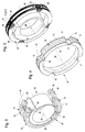
- Fig. 2 shows the assembled state of the angle measuring device 1/1 in a basic arrangement.
- Fig. 3 shows a measuring coil 50, the basic structure corresponds to the measuring coil 2 from FIGS. 1 and 2.
- the measuring coil 50 is designed as a so-called “air coil” and maintains its stability through a so-called “baking lacquer technique”.
- the measuring coil 50 also has a first coil ring 51 and a second coil ring 52, each in a first coil section 53 or 54 and a second Coil section 55 and 56 are divided.
- the cylinder section 64 or the entire measuring body 63 can a positive feedback or negative feedback material be, with the feedback material as a die Inductance reinforcing material is a ferromagnetic Metal is provided.
- negative feedback material or damping material can on the other hand for the Measuring body 63 is a non-magnetic metallic material be provided.
- the cylinder section 64 also as separate components on a cylinder can be applied, in which case the Cylinder made of a neutral material with respect to its Influencing the inductors is formed.
- the measurement signal the "air coil” 50 becomes the measuring coil accordingly 2 from Fig. 1 on the connecting lines 60 and 61 removed.
- Fig. 3 was on the representation of a second Measuring coil and the transmitter coil for reasons of clarity waived.
- the second measuring coil and the Transmitter coil could e.g. in the Diameter may be larger than that shown first measuring coil and enclose it.
- Fig. 4 shows a special, approximately ring-shaped Coil body 67, on which, for example 1 and 2 in a simple manner is windable.
- the coil former 67 has a winding cylinder 68 on which in the axial direction of its Cylinder axis 69 at its ends by a radial extended web wall 70 or 71 is limited.
- This two web walls 70 and 71 each delimit on the outside the winding area in which on the bobbin 67 corresponding windings according to the basic diagram 1 can be wound up.
- a radial separator 72 is provided by which the winding cylinder 68 axially in a front and a rear winding area 73 and 74 is divided.
- the separating web 72 is interrupted in the circumferential direction, so that four each offset by 90 ° to each other Junction areas 75, 76, 77 and 78 are formed become. Through these intersection areas 75 to 78 are on the coil body 67 in a simple manner electromagnetic Induction coils with winding geometries of the ones to be wound Coils according to the three coils from FIG. 1 can be accommodated.
- Fig. 5 shows the bobbin 67 with finished wound Coils 79, 80 and 81, these coils 79, 80 and 81 are wound into each other in such a way that from the illustration 5 the individual coils can no longer be recognized individually are.
- eyelets 82, 83, 84 and 85 are provided which connecting elements to the according to necessary connection lines or measuring lines, as they are indicated in Fig. 1 represent.
- the corresponding one of the measuring coil 3 Measuring coil in Fig. 5 around a vertical axis Must be turned 180 ° so that the eyelets 84 and 85 in the front portion of the bobbin shown 67 are arranged.
- FIG. 6 is the block diagram of a differential transformer system in principle with a transmitter coil 105 and two Measuring coils 87 and 91 shown.
- the transmitter coil 105 is for generating the alternating magnetic field intended.
- the two measuring coils 87 and 91 can different in diameter be so that they are not directly wrapped in each other, but have a radial distance from each other.
- the two measuring coils 87 and 91 larger in diameter than that Transmitter coil 105, with all coils 87, 91 and 105 the measuring body 45 from FIG. 1 is arranged.
- intersection areas 88 and 89 of the first measuring coil 87 in a horizontal plane 90 these intersection areas 88 and 89 diametrically opposite.
- the second measuring coil 91 shows its two crossing areas 92 and 93 in a vertical plane rotated by 90 ° to the horizontal plane 90 94, the two intersection areas 92 and 93 are also diametrically opposed.
- 6 is a carrier frequency generator 95 recognizable by which the transmitter coil 105 over the two Connection lines 96, 97 with a carrier frequency voltage is applied so that an alternating magnetic field is generated by the transmitter coil 105.
- This Alternating field passes through the two measuring coils 87 and 91, see above that at their ends through the connecting lines 106, 107 or 108, 109 a corresponding measuring voltage can be removed is, which by a respective demodulator 100 or 102 can be demodulated for further processing.
- the Measuring voltages are directly from the winding ends in the crossing areas 88 and 93 of the two measuring coils 87 and 91 removed.
- 6 is the measuring body 45 in shown an angular position in which the end edges of the cylinder section 46 at a set angle ⁇ is arranged from 45 ° to the horizontal 90.
- the curves of the individual voltages that is to say the carrier frequency voltage 110 of the transmitter coil 105 and the two measurement signals or measurement voltages 111 and 112 of the two coils 87 and 91, are shown in FIG. 7.
- a rotation angle of 0 ° for example, no measuring voltage is induced in the first measuring coil 87.
- This 0 ° position would be reached, for example, if the measuring body 45 from FIG. 6 with the ends of its cylinder sections 46 is in the vertical plane 94.
- a maximum measuring voltage 112 is induced in the second measuring coil 91.
- the measuring voltage 111 of the first measuring coil 87 increases to its maximum, while the measuring voltage 112 of the second measuring coil 91 drops to zero.
- the measuring voltage of the first measuring coil 87 decreases to zero, while the measuring voltage 112 of the second measuring coil 91 increases to its maximum value.
- a phase shift of the measuring signal by 90 ° occurs, so that the measuring voltage 112 has a negative sign with respect to the carrier frequency voltage 110 from the angle of rotation 90 ° to the angle of rotation 180 ° or ⁇ , so to speak.
- the measuring voltage 111 of the first measuring coil 87 when the measuring body 45 passes through the 180 ° angular position, a phase shift of 90 ° also occurs, so that when the measuring body 45 is rotated further to 270 °, the measurement signal also grows to a maximum value , but has a negative sign with respect to the carrier frequency voltage 110.
- the second measuring signal of the second measuring coil 91 is reduced to zero again.
- a further phase shift of 90 ° occurs in this second measuring signal 112, so that 360 ° and in the position 2 112 ⁇ , upon further rotation of the measuring body 45, the measuring voltage again increases, but now has a positive sign with respect to the carrier frequency voltage 110.
- the first measuring voltage 111 of the first measuring coil is again reduced to zero. From this signal curve of the measuring voltages 111 and 112, the angle of rotation of the measuring body 45 and its direction of rotation can be determined in a simple manner by demodulating the two measuring signals. From the 90 ° phase shift of the measuring signal 111 of the measuring coil 87 occurring after 180 ° and 360 ° respectively or from the 90 ° phase shift of the measuring signal at 90 ° and 270 °, the direction of rotation of the Measuring body 45 can be determined in a simple manner.
- phase shifts occur due to the geometrical structure of the two measuring coils 87 and 91 after every half revolution by 180 ° of the measuring body 45, with the second measuring coil 91 correspondingly having to be offset by 90 ° in the circumferential direction from the first measuring coil 87, and thus whose phase shifts occur delayed by 90 °.
- the two measurement signals 111 and 112 are identical Coil geometry of both measuring coils 87 and 91, in their The course over time is identical and 90 ° in the direction of rotation of the measuring body 45 shifted.
- the inductive angle measuring device becomes a non-contact encoder for position reporting a measuring body by generating an analog signal via provided a rotation angle of 360 °.
- the coil arrangement is on the one hand on a coil former or also possible as an air coil in baked enamel technology.
- the individual coils can be used in a rotary winding technique be produced in one operation so that extremely low manufacturing costs with optimal inductive relationships of the individual coils to each other surrender.
- the angle measuring device according to the invention is ideal for a hollow shaft arrangement or for an axis application suitable, in particular with a hollow shaft arrangement the measuring body, for example, in the inner wall of the Hollow shaft can be arranged and the actual coil system arranged within this rotating measuring body can be. Also, like this can also be seen from the drawing figures it becomes clear the complete coil arrangement, in particular when wound as a unit on a bobbin is already one at any point existing shaft can be used because it is in axial Direction with appropriate dimensioning in diameter pushed onto the shaft at the intended location can be.
- the angle measuring device according to the invention is therefore not limited to use at one shaft end, as is the case for example with those described at the beginning Resolvers is the case.
- the material of the measuring body as Swivel anchor with an arch part extending approximately 180 ° or cylinder section can provide signal amplification in the individual coil sections or also one Attenuation of the signal in the individual coil sections can be achieved so that also with respect to the measuring body variable configuration is possible.
- this measuring body does not have to have its own storage, for example be arranged on each drive shaft can.
- the coil arrangement can also have its own housing, for example 3, be formed, which further increases the variability of the area of application becomes.
- the Carrier frequency can be chosen extremely high, resulting in a extremely high sensor speed with high speed Sensitivity to the change in the angle of rotation of the Measuring body is reached.
- the signal evaluation can be done with commercially available inexpensive integrated circuits be carried out, which in turn only a small Cost expenditure when using the invention Angle measuring device is reached. Because the magnetic Coupling between the individual measuring coils and the transmitter coil extremely large due to the integrated windings is, only an extremely low energy consumption of the entire measuring system.
Landscapes
- Physics & Mathematics (AREA)
- General Physics & Mathematics (AREA)
- Transmission And Conversion Of Sensor Element Output (AREA)
- Measurement Of Length, Angles, Or The Like Using Electric Or Magnetic Means (AREA)
Abstract
Induktive Winkelmeßvorrichtungen sind in der Regel mit
einer elektromagnetischen Meßspule (2) ausgestattet, in
welche durch ein magnetisches Wechselfeld eine Meßspannung
induziert wird. Durch einen relativ zur Meßspule (2)
drehend bewegbaren Meßkörper (4) wird die Induktivität
und die Meßspannung der Meßspule (4) in Abhängigkeit der
Lage des Meßkörpers (4) zur Meßspule (2) beeinflußt. Zum
Erreichen einer optimalen induktiven Kopplung zwischen
dem magnetischen Wechselfeld und der Meßspule (2) ist die
Meßspule (2) aus zwei Spulenringen gebildet, welche gegensinnig
gewickelt und koaxial zueinander angeordneten
sind. Die Spulenringe sind in zwei sich diametral gegenüberliegende
Spulenabschnitte unterteilt, wobei sich die
Wicklungen der beiden Spulenringe derart überkreuzen, daß
der erste Spulenabschnitt des ersten Spulenringes in
Richtung der Spulenachse (9) vor dem ersten Spulenabschnitt
des zweiten Spulenringes und der zweite Spulenabschnitt
des ersten Spulenringes hinter dem zweiten Spulenabschnitt
des zweiten Spulenringes angeordnet ist.

Description
Die Erfindung betrifft eine Induktive Winkelmeßvorrichtung mit wenigstens einer elektromagnetischen Meßspule, in welche durch wenigstens ein magnetisches Wechselfeld eine Meßspannung induziert wird, und mit einem drehend antreibbaren, die Induktivität und die Meßspannung der Meßspule in Abhängigkeit seiner Winkelstellung gegenüber der Meßspule beeinflussenden Meßkörper mit wenigstens einem sich über einen Zentriwinkel von etwa 180o erstreckenden Zylinderabschnitt, wobei die Meßspule aus einem ersten und einem zweiten Spulenring gebildet ist, welche koaxial zueinander angeordnet sind und jeweils in einen ersten und zweiten Spulenabschnitt unterteilt sind, die sich jeweils diametral gegenüberliegen, und wobei sich die Wicklungen der beiden Spulenringe derart überkreuzen, daß der erste Spulenabschnitt des ersten Spulenrings in einer Achsrichtung der Spulenachse axial versetzt vor dem ersten Spulenabschnitt des zweiten Spulenrings und der zweite Spulenabschnitt des ersten Spulenrings in der gleichen Achsrichtung axial versetzt hinter dem zweiten Spulenabschnitt des zweiten Spulenrings angeordnet ist. The invention relates to an inductive angle measuring device with at least one electromagnetic measuring coil, into which a measuring voltage is induced by at least one alternating magnetic field, and with a rotatingly drivable measuring body influencing the inductance and the measuring voltage of the measuring coil as a function of its angular position relative to the measuring coil, with at least one measuring body which are over a central angle of about 180 o extending cylinder portion, wherein the measuring coil comprises a first and a second coil ring is formed coaxial with each other and are each divided into a first and second coil portions, which oppose each other diametrically, and wherein the windings cross over of the two coil rings such that the first coil section of the first coil ring is axially offset in an axial direction of the coil axis in front of the first coil section of the second coil ring and the second coil section of the first Coil ring is arranged axially offset in the same axial direction behind the second coil section of the second coil ring.
Es sind Winkelmeßvorrichtungen bekannt, welche wenigstens eine elektromagnetische Meßspule aufweisen, in welcher durch ein magnetisches Wechselfeld eine Meßspannung induziert wird. Solche induktive Winkelmeßvorrichtungen ermöglichen die einfache elektrische Erfassung und Messung mechanischer Größen, indem diese mechanischen Größen in ein analoges Spannungssignal umwandelbar sind. Zur Winkelmessung wird dabei ein im induktiven Wirkungsbereich der Meßspule angeordneter Meßkörper rotierend angetrieben, so daß in Abhängigkeit von der Winkelstellung des Meßkörpers gegenüber der Meßspule deren Induktivität und damit deren Meßspannung beeinflußt wird. Als Meßkörper dienen dabei im wesentlichen Meßzylinder, deren Umfangsfläche mit einem etwa halbzylindrisch ausgebildeten, aus einem speziellen, die Induktivität beeinflussenden Material bestehenden Werkstoff gebildeten Körperabschnitt versehen ist. Die bekannten Winkelmeßvorrichtungen können dabei aus zwei Spulen oder Spulenabschnitten gebildet sein, die in einer induktiven Halbbrücke zusammengeschaltet sind oder sie arbeiten auf dem Prinzip eines Differentialtransformators.Angle measuring devices are known, which at least have an electromagnetic measuring coil in which a measuring voltage induced by an alternating magnetic field becomes. Such inductive angle measuring devices enable the simple electrical detection and measurement mechanical quantities by dividing these mechanical quantities into an analog voltage signal can be converted. For angle measurement becomes one in the inductive range the measuring body arranged rotatingly driven, so that depending on the angular position of the Measuring body relative to the measuring coil, its inductance and so that their measuring voltage is influenced. As a measuring body serve essentially measuring cylinders, their peripheral surface with an approximately semi-cylindrical design a special material that influences the inductance existing material formed body section is provided. The known angle measuring devices can formed from two coils or coil sections be interconnected in an inductive half-bridge are or they work on the principle of a differential transformer.
Eine solche induktive Halbbrücke besteht aus zwei in Serie geschalteten Spulen, welche mit einer Wechselspannung von beispielsweise 10 kHz gespeist werden. Durch diese Wechselspannung wird in den Spulen ein entsprechender Wechselstrom I hervorgerufen, durch welchen ein magnetischer Wechselfluß erzeugt wird. Dieser Wechselfluß induziert nach dem Induktionsgesetz eine Selbstinduktionsspannung, welche in beiden Spulen bei gleicher Ausbildung der Spulen die gleiche Größe aufweist. Sind nun diese beiden Spulen im Umfangsbereich eines rotatorisch angetriebenen Meßkörpers angeordnet und werden die Induktivitäten der beiden Spulen bei der drehenden Bewegung des Meßkörpers nacheinander unterschiedlich beeinflußt, so entsteht eine vom Drehwinkel des Meßkörpers abhängige und zu diesem Winkel proportionale Spannungsänderung, welche im Verbindungsbereich zwischen den beiden Spulen abnehmbar ist. Diese Spannungsänderung kann von einem Demodulator in ein entsprechendes Gleichspannungssignal umgewandelt werden, welches dann entsprechend proportional zur Winkeländerung bzw. dem Drehwinkel des Meßkörpers ist. Auf diese Art läßt sich in einfacher Weise der Drehwinkel eines Meßkörpers über ein Spannungssignal ermitteln. Die Ausgangssignale sind dabei stufenlos und haben einen stetigen Verlauf. Induktive Winkelmeßvorrichtungen, welche nach dem Prinzip der induktiven Halbbrücke ausgelegt sind, dienen zum Messen von Winkeln mit einem linearen Meßbereich von +/- 45°. Dies bedeutet, daß derartige nach einer induktiven Halbbrücke ausgelegten Winkelmeßvorrichtungen für eine Drehwinkelmessung über einen Winkelbereich von 360° nicht oder nur bedingt geeignet sind. Such an inductive half-bridge consists of two in series switched coils, which with an AC voltage of 10 kHz, for example. Through this AC voltage becomes a corresponding one in the coils Alternating current I caused by which a magnetic Alternating flow is generated. This alternating flow induces according to the law of induction, a self-induction voltage, which in both coils with the same training the coils are the same size. Now are these two coils in the peripheral area of a rotationally driven Arranged measuring body and become the inductors of the two coils during the rotating movement of the Measuring body influenced differently one after the other, so arises depending on the angle of rotation of the measuring body and voltage change proportional to this angle, which removable in the connection area between the two coils is. This voltage change can be from a demodulator converted into a corresponding DC voltage signal which are then proportionally proportional to Angle change or the angle of rotation of the measuring body. In this way, the angle of rotation can be easily of a measuring body using a voltage signal. The Output signals are stepless and have a constant Course. Inductive angle measuring devices, which designed according to the principle of the inductive half-bridge are used to measure angles with a linear Measuring range of +/- 45 °. This means that such after an inductive half-bridge designed angle measuring devices for a rotation angle measurement over an angular range of 360 ° are not suitable or only suitable to a limited extent.
Solche Winkelmessungen über eine Winkelbereich von 360°
und mehr können allerdings von induktiven Winkelmeßvorrichtungen,
welche nach dem Differentialtransformatorprinzip
arbeiten gemessen werden. Dazu sind beispielsweise
Winkelmeßvorrichtungen, welche als sogenannte
"Resolver" bezeichnet werden, bekannt geworden (Prospekt
Firma Baumer electric, TTW 4/96 Nr. 800164). In dieser
Firmenschrift wird ein als rein passives Winkelmeßsystem
ausgelegter Miniatur-Resolver beschrieben, welcher eigentlich
ein Transformator mit winkelabhängiger, elektromagnetischer
Kopplung ist. Dieser Resolver besitzt einen
rein passiven Rotor ohne Spulen. Eine feststehende Primärspule
wird von einer Wechselspannung gespeist. In ihrem
Inneren erzeugt sie somit ein homogenes, magnetisches
Wechselfeld. Als Aufnehmer befinden sich innerhalb dieser
Sendespule stationäre Empfängerspulen oder auch Meßspulen,
die von diesem homogenen, magnetischen Wechselfeld
durchsetzt werden. Folglich wird in diesen im Inneren der
Sendespule angeordneten Meßspulen eine zu messende Spannung
induziert, welche von der induktiven Kopplung zwischen
der Sendespule und den Meßspulen abhängig ist. Ohne
weitere Beeinflussung dieses Systems werden in den Meßspulen
Spannungen gleicher Größe und je nach Wickelrichtung
der einzelnen Spulen mit unterschiedlichem oder
gleichem Vorzeichen erzeugt.
In der Sendespule ist desweiteren ein Rotor angeordnet,
welcher ein ferromagnetisches Teil aufweist, das umlaufend
mit dem Rotor rotiert und die in Umfangsrichtung
gleichmäßig hintereinander angeordneten Meßspulen nacheinander
beeinflußt. Dieser ferromagnetische Teil des Rotors
verändert dabei das elektromagnetische Wechselfeld
im Inneren der Sendespule so, daß in den Meßspulen in Abhängigkeit
vom Drehwinkel des Rotors unterschiedliche
Spannungen induziert werden. Es sind dabei vier Meßspulen
vorgesehen, welche einander paarweise, sich diametral gegenüberliegend
zugeordnet sind. Diese paarweisen Meßspulen
sind gegensinnig gewickelt und verlaufen mit ihrer
Spulenachse parallel zur Spulenachse der Sendespule, welche
ihrerseits wiederum parallel und konzentrisch zur
Drehachse des Rotors angeordnet ist. Jedes Meßspulenpaar
erzeugt dabei eine drehwinkelabhängige Meßspannung, so
daß durch diese Meßspannung eines jeden Spulenpaares ein
Drehwinkel von insgesamt 360° erfaßbar ist. Da die Meßspulen
in Umfangsrichtung paarweise um 90o versetz zueinander
angeordnet sind, können aus den beiden um 90° phasenverschobene
Meßspannungen sowohl Rotorwinkel als auch
Drehrichtung des Rotors bestimmt werden.Such angular measurements over an angular range of 360 ° and more can, however, be measured by inductive angle measuring devices which operate according to the differential transformer principle. For this purpose, angle measuring devices, for example, which are referred to as so-called “resolvers”, have become known (prospectus Baumer electric, TTW 4/96 No. 800164). This company publication describes a miniature resolver designed as a purely passive angle measuring system, which is actually a transformer with an angle-dependent, electromagnetic coupling. This resolver has a purely passive rotor without coils. A fixed primary coil is powered by an AC voltage. It creates a homogeneous magnetic alternating field inside. Stationary receiver coils or measuring coils, which are penetrated by this homogeneous, alternating magnetic field, are located as receivers within this transmitter coil. Consequently, a voltage to be measured is induced in these measuring coils arranged inside the transmitting coil, which voltage is dependent on the inductive coupling between the transmitting coil and the measuring coils. Without further influencing this system, voltages of the same size and, depending on the winding direction of the individual coils, with different or the same sign are generated in the measuring coils.
Furthermore, a rotor is arranged in the transmitting coil, which has a ferromagnetic part which rotates all round with the rotor and which successively influences the measuring coils arranged one after the other in the circumferential direction. This ferromagnetic part of the rotor changes the alternating electromagnetic field inside the transmitter coil so that different voltages are induced in the measuring coils depending on the angle of rotation of the rotor. Four measuring coils are provided, which are assigned to one another in pairs, diametrically opposite one another. These paired measuring coils are wound in opposite directions and run with their coil axis parallel to the coil axis of the transmitter coil, which in turn is arranged parallel and concentric to the axis of rotation of the rotor. Each pair of measuring coils generates a measuring voltage that is dependent on the angle of rotation, so that a total angle of 360 ° can be detected by this measuring voltage of each pair of coils. Since the measuring coils are arranged in pairs circumferentially offset by 90 o to each other, both the rotor angle and the direction of rotation of the rotor can be determined from the two measuring voltages phase-shifted by 90 °.
Dieser bekannte Resolver zeichnet sich durch eine eingeschränkte induktive Kopplung zwischen der Sendespule und den Meßspulen aus, da die Sendespule außerhalb der eigentlichen Meßspulen angeordnet ist und somit die elektromagnetische Kopplung nicht optimal ist. Desweiteren ist auch aufgrund der vorgesehenen einzelnen Meßspulen, welche sich paarweise diametral gegenüberliegen ein komplizierter mechanischer Aufbau notwendig. Auch können solche Resolver nach dem beschriebenen Aufbau nicht in beliebiger Größe hergestellt werden, da sich mit zunehmender Baugröße des Resolvers die induktive Kopplung zwischen der Sendespule und den Meßspulen verschlechtert und somit die Meßgenauigkeit einer solchen induktiven Winkelmeßvorrichtung mit zunehmender Baugröße ungenauer wird. Außerdem wird ein solcher Resolver mit zunehmender Baugröße empfindlicher gegen äußere Störeinflüsse.This known resolver is characterized by a restricted inductive coupling between the transmitter coil and the measuring coils, since the transmitter coil outside of the actual Measuring coils is arranged and thus the electromagnetic Coupling is not optimal. Furthermore is also due to the provided individual measuring coils, which are diametrically opposed in pairs a complicated one mechanical construction necessary. Can too such resolvers not according to the structure described any size can be made, as with increasing Size of the resolver the inductive coupling between the transmitter coil and the measuring coils deteriorated and thus the measuring accuracy of such an inductive angle measuring device becomes inaccurate with increasing size. In addition, such a resolver increases in size more sensitive to external interference.
Weiterhin ist eine Winkelmeßvorrichtung bekannt (DE 42 43
022 A1), die einen Rotor aufweist, der zwei etwa halbkreisförmige
Zylinderabschnitte aufweist. Diese Zylinderabschnitte
sind in axialer Richtung der Drehachse des Rotors
axial hintereinander liegend angeordnet und in Umfangsrichtung
um 180° gegeneinander versetzt. Dem Rotor
ist eine Meßspule zugeordnet, die aus zwei Spulenringen
gebildet wird und ortsfest, koaxial zum Rotor angeordnet
ist. Die beiden Spulenringe sind in jeweils zwei sich etwa
über einen Zentriwinkel von 180° erstreckende Spulenabschnitte
unterteilt, wobei der jeweilige erste Spulenabschnitt
eines Spulenrings axial im Bereich des vorderen
Zylinderabschnittes und der jeweilige zweite Spulenabschnitt
eines Spulenrings axial im Bereich des hinteren
Zylinderabschnittes des Rotors angeordnet ist. Die so
stufenförmig gewickelten Spulenringe überkreuzen sich und
stehen mit ihren Spulenabschnitten jeweils mit beiden Zylinderabschnitten
des Rotors während einer vollen Umdrehung
des Rotors in Wirkverbindung. Mit dieser Spulenanordnung
sollen Verschiebungen des Rotors in allen Richtung
relativ zur Meßspule kompensiert werden. Da bei dieser
bekannten Winkelmeßvorrichtung keine Sendespule vorgesehen
ist, sondern die Meßspulen selbst mit der Trägerfrequenz
zum Aufbau eines Magnetfeldes beaufschlagt wird,
können solche Winkelmeßvorrichtungen auch größer ausgebildet
werden. Um nun Schwankungen des Rotors jeglicher
Art kompensieren zu können, sind die Zylinderabschnitte
des Rotors in ihrer Breite in Richtung der Drehachse des
Rotors größer ausgebildet, als die Breite eines einzelnen
Spulenrings. Dies hat bei größeren Baugrößen der Winkelmeßvorrichtung
eine erhöhte Baulänge zu Folge. Außerdem
wird der lineare Meßbereich, der bis zu +/- 120° betragen
soll weiter eingeschränkt, da auch die Kreuzungspunkte
der Spulenringe dieser erhöhten Breite angepaßt werden
müssen. Desweiteren ist der Aufbau des Rotors mit seinen
zwei Zylinderabschnitten kompliziert, da der Rotor, um
während einer vollen Umdrehung mit seinen Zylinderabschnitten
wechselweise mit den Spulenabschnitten in Wirkverbindung
treten zu können, sowohl in Umfangsrichtung
als auch in axialer Richtung seiner Drehachse abgestuft
ausgebildet sein muß. Eine Winkelmessung um volle 360°
ist auch bei dieser Winkelmeßvorrichtung aufgrund des
eingeschränkten linearen Meßbereiches nicht oder nur bedingt
möglich. Da diese Winkelmeßvorrichtung allerdings
zur Bestimmung einer Drosselklappenstellung bei Kraftfahrzeugen
vorgesehen sein soll, ist dies auch nicht notwendig,
da eine Drosselklappe auch keine Drehung um 360°
ausführt.Furthermore, an angle measuring device is known (
Demgemäß liegt der Erfindung die Aufgabe zugrunde, eine induktive Winkelmeßvorrichtung zur Verfügung zu stellen, bei welcher zum Erreichen eines möglichst großen linearen Meßbereichs eine optimale induktive Kopplung zwischen dem magnetischen Wechselfeld und der oder den verwendeten Meßspulen im wesentlichen unabhängig von der Baugröße der Winkelmeßvorrichtung erreicht wird, wobei gleichzeitig ein möglichst einfacher und kostengünstiger Aufbau gewährleistet sein soll.Accordingly, the invention has for its object a to provide inductive angle measuring device, in which to achieve the largest possible linear Measuring range an optimal inductive coupling between the magnetic alternating field and the one or more used Measuring coils essentially independent of the size of the Angle measuring device is reached, at the same time a simple and inexpensive construction guaranteed should be.
Die Aufgabe wird in Zusammenwirken mit den Merkmalen des
Oberbegriffes des Anspruches 1 erfindungsgemäß dadurch
gelöst, daß die Spulenringe der Meßspule gegensinnig gewickelt
sind, und daß eine koaxial zur Meßspule angeordnete
Sendespule vorgesehen ist, die aus zwei entgegengesetzt
gewickelten Spulenringen besteht, welche derart
axial hintereinander liegend angeordnet sind, daß der erste
Spulenring axial im Bereich der vorderen Spulenabschnitte
und der zweite Spulenring axial im Bereich der
hinteren Spulenabschnitte angeordnet ist.The task is performed in conjunction with the characteristics of the
Preamble of
Durch die erfindungsgemäße Ausgestaltung wird eine berührungslose, induktive Winkelmeßvorrichtung zur Verfügung gestellt, mit der die Winkelposition eines Meßkörpers durch Erzeugen eines Analogsignals über einen Drehwinkel von 360° ermittelbar ist. Die erfindungsgemäße Winkelmeßvorrichtung zeichnet sich dabei durch einen einfachen mechanischen und einen einfachen Aufbau der elektronischen Auswerteeinrichtung aus. Desweiteren wird unabhängig von der Baugröße der Winkelmeßvorrichtung eine optimale induktive Kopplung zwischen der Sendespule und der Meßspule erreicht, da diese sich umlaufend in unmittelbarer räumlicher Nähe befinden.The configuration according to the invention enables a contactless, inductive angle measuring device available with which the angular position of a measuring body by generating an analog signal over an angle of rotation of 360 ° can be determined. The angle measuring device according to the invention is characterized by a simple mechanical and a simple structure of the electronic Evaluation device. Furthermore, it becomes independent of the size of the angle measuring device an optimal inductive Coupling between the transmitter coil and the measuring coil achieved because this is all around in immediate spatial Proximity.
Dazu weist die Meßspule einen ersten und einen zweiten Spulenring auf, welche gegensinnig gewickelt sind und koaxial zueinander angeordnet sind. Jeder der Spulenringe ist jeweils in einen ersten und einen zweiten Spulenabschnitt unterteilt, welche sich jeweils bezüglich der Spulenachse diametral gegenüberliegen. Diese Wicklungen der beiden Spulenringe überkreuzen sich, so daß der erste Spulenabschnitt des ersten Spulenrings in einer Achsrichtung der Spulenachse der Meßspule axial versetzt vor dem ersten Spulenabschnitt des zweiten Spulenrings liegt. Dementsprechend liegt der zweite Spulenabschnitt des ersten Spulenrings in gleicher Achsrichtung axial versetzt hinter dem zweiten Spulenabschnitt des zweiten Spulenrings. Dies bedeutet, daß sich die beiden Spulenringe bzw. deren Wicklungen diametral gegenüberliegend überkreuzen.For this purpose, the measuring coil has a first and a second Coil ring, which are wound in opposite directions and are arranged coaxially to each other. Each of the coil rings is in a first and a second coil section divided, which each with respect to the Coil axis are diametrically opposite. These windings of the two coil rings cross each other, so that the first Coil section of the first coil ring in an axial direction the coil axis of the measuring coil axially offset from the lies first coil section of the second coil ring. Accordingly, the second coil section of the first Coil ring axially offset in the same axial direction behind the second coil section of the second coil ring. This means that the two coil rings or cross their windings diametrically opposite one another.
Der vorgesehene Meßkörper ist konzentrisch zur Spulenachse der Meßspule angeordnet und weist auf seiner Mantelfläche einen Zylinderabschnitt auf, welcher sich über einen Zentriwinkel von etwa 180° erstreckt. Dieser Zylinderabschnitt erstreckt sich in Achsrichtung der Spulenachse wenigstens über die Breite einer der Spulenabschnitte, so daß bei dessen Rotation in Abhängigkeit des Drehwinkels des Meßkörpers abwechselnd die beispielsweise im axial vorderen Bereich liegenden Spulenabschnitte der beiden Spulenringe beeinflußt werden, sofern der Zylinderabschnitt des Meßkörpers in diesem axialen Bereich angeordnet ist. Desgleichen gilt für die axial hinteren Spulenabschnitte der beiden Spulenringe, wenn der Zylinderabschnitt entsprechen in deren Axialbereich angeordnet ist. Somit wird durch den Zylinderabschnitt in Abhängigkeit vom Drehwinkel des Meßkörpers relativ zur Meßspule deren Induktivität verändert. Durch diese wechselseitige Beeinflussung der Spulenabschnitte, von denen der eine dem ersten Spulenring und der andere dem zweiten Spulenring zugeordnet ist, wird zwischen den Anschlußleitungen der in Reihe geschalteten, gegensinnig gewickelten Spulenringe eine Meßspannung erzeugt.The intended measuring body is concentric to the coil axis arranged the measuring coil and has on its outer surface a cylinder section, which extends over a Central angle extends from about 180 °. This cylinder section extends in the axial direction of the coil axis at least across the width of one of the coil sections, so that when it rotates depending on the Angle of rotation of the measuring body alternately, for example in the axially front area lying coil sections two coil rings are affected, provided the cylinder section of the measuring body arranged in this axial area is. The same applies to the axially rear Coil sections of the two coil rings when the cylinder section correspond arranged in their axial area is. Thus, depending on the cylinder section from the angle of rotation of the measuring body relative to the measuring coil whose inductance changed. Through this mutual Influencing the coil sections, one of which the first coil ring and the other the second coil ring is assigned between the connecting lines of the coil rings connected in series, wound in opposite directions generates a measuring voltage.
Das magnetische Wechselfeld wird durch eine Sendespule erzeugt, welche mit einer entsprechenden Wechselspannung und damit einem entsprechenden Wechselstrom beaufschlagt wird. Durch diesen Wechselstrom wird das benötigte magnetische Wechselfeld erzeugt, durch welches in die Meßspule eine entsprechende Spannung induziert wird. Die Sendespule ist dabei koaxial zur Meßspule angeordnet und besteht aus zwei entgegengesetzt gewickelten Spulenringen, welche axial in Richtung der Spulenachse hintereinander liegend angeordnet sind. Dabei befindet sich der erste Spulenring der Sendespule axial im Bereich der vorderen Spulenabschnitte der Spulenringe der Meßspule und der zweite Spulenring der Sendespule axial im Bereich der hinteren Spulenabschnitte. Dadurch werden in die einzelnen Spulenabschnitte des jeweiligen Spulenrings der Meßspule entgegengesetzte Meßspannungen induziert. Durch den Zylinderabschnitt des Meßkörpers wird die Induktivität der im Wirkungsbereich des Meßkörpers liegenden Spulenabschnitte in Abhängigkeit vom Rotationswinkel des Meßkörpers bzw. seines Zylinderabschnittes abwechselnd beeinflußt, so daß die induzierten Ausgangsspannungen der Meßspule in Abhängigkeit vom Drehwinkel des Zylinderabschnittes des Meßkörpers verändert wird. The alternating magnetic field is generated by a transmitter coil generated, which with a corresponding AC voltage and thus applied to a corresponding alternating current becomes. This alternating current makes the required magnetic Alternating field generated, through which in the measuring coil a corresponding voltage is induced. The transmitter coil is arranged coaxially to the measuring coil and exists from two oppositely wound coil rings, which lying axially one behind the other in the direction of the coil axis are arranged. The first coil ring is located here the transmitter coil axially in the area of the front coil sections the coil rings of the measuring coil and the second coil ring the transmitter coil axially in the area of the rear coil sections. As a result, the individual coil sections of the respective coil ring of the measuring coil opposite Measuring voltages induced. Through the cylinder section the measuring body is the inductance of the Area of action of the measuring body lying coil sections depending on the rotation angle of the measuring body or its cylinder section alternately influenced, so that the induced output voltages of the measuring coil in dependence from the angle of rotation of the cylinder section of the measuring body is changed.
Gemäß Anspruch 2 erstreckt sich der Zylinderabschnitt des
Meßkörpers vorzugsweise über die gesamte Breite der benachbarten
Spulenabschnitte, wodurch eine Verstärkung der
Beeinflussung der Induktivität der Spulenabschnitte der
beiden Spulenringe bewirkt wird. Somit wird durch diese
erfindungsgemäße Ausgestaltung das Meßsignal verstärkt.
Da nur ein Zylinderabschnitt benötigt wird, sind auch die
Herstellkosten für den Meßkörper äußerst gering. Andererseits
kann auch die Baulänge des Meßkörpers und somit der
gesamten Winkelmeßvorrichtung gering gehalten werden.According to
Gemäß Anspruch 3 kann zur Drehrichtungserkennung eine
zweite Meßspule vorgesehen sein, die in Umfangsrichtung
mit ihren Spulenabschnitten um 90° versetzt zur ersten
Meßspule angeordnet ist. Der Meßkörper kann dabei ebenfalls
einen halbzylindrischen Zylinderabschnitt aufweisen,
der sich über die Länge eines Spulenrings oder auch
über die gesamte Länge beider hintereinander liegender
Spulenringe erstreckt. Zum Erreichen einer möglichst
kleinen Baugröße können die beiden Meßspulen zumindest
bereichsweise ineinander gewickelt sein.According to
Gemäß Anspruch 4 wird die induktive Kopplung dadurch erheblich
verbessert, daß auch die Wicklungen der Sendespule
mit den Wicklungen der beiden Meßspulen bereichsweise
ineinander gewickelt sind, so daß eine optimale magnetische
Kopplung zwischen den einzelnen Spulenabschnitten
und der Sendespule erreicht wird.According to
Durch die Ausgestaltungen der Ansprüche 5 bis 7, die einen
speziell für die Aufnahme der Meßspulen und der Sendespule
ausgestalteten Spulenkörper betreffen, wird eine
Spuleneinheit zur Verfügung gestellt, die äußerst variabel
für die unterschiedlichsten Einsatzzwecke einsetzbar
ist und eine hohe Widerstandsfähigkeit gegen äußere Beschädigungen
aufweist.By the embodiments of
Für einen weiteren variablen Einsatz können die einzelnen
Spulen oder auch die ineinander gewickelten Spulen gemäß
Anspruch 8 auch als sog. Luftspulen ausgebildet sein.For further variable use, the individual
Coils or the coils wound into one another according to
Es versteht sich, daß die Meßspulen und die Sendespule in ihrem Durchmesser auch unterschiedlich ausgebildet sein können, so daß sie ineinander schiebbar sind und auch somit eine äußerst gute elektromagnetische Kopplung zwischen den einzelnen Spulenabschnitten der Meßspule und den Spulenringen der Sendespule erreicht wird.It is understood that the measuring coils and the transmitter coil in their diameter can also be designed differently can, so that they can be pushed into each other and thus an extremely good electromagnetic coupling between the individual coil sections of the measuring coil and the coil rings of the transmitter coil is reached.
Anhand der Zeichnung wird im folgenden die Erfindung näher erläutert. Es zeigt:
- Fig. 1
- eine Winkelmeßvorrichtung mit zwei Meßspulen, einer Sendespule und einem Meßkörper in perspektivischer Explosionsdarstellung;
- Fig. 2
- die Meßspulen, die Sendespule und den Meßkörper in funktionsrichtiger Lage in perspektivisch vergrößerter Darstellung;
- Fig. 3
- einen perspektivischen Teilschnitt einer als Luftspule ausgebildeten Meßspule mit Meßkörper;
- Fig. 4
- einen Spulenkörper zum Ineinanderwickeln von zwei Meßspulen und einer Sendespule;
- Fig. 5
- den Spulenkörper aus Fig. 4 mit fertig gewickelten Meßspulen und Sendespule in perspektivischer Darstellung;
- Fig. 6
- ein Blockschaltbild einer Differentialtrafoschaltung mit Sendespule und zwei Meßspulen;
- Fig. 7
- einen Signalverlauf einer Trägerfrequenzspannung und zweier Meßspannungen zweier Meßspulen bei einer Differentialtransformatorschaltung in Abhängigkeit vom Drehwinkel des Meßkörpers;
- Fig. 1
- an angle measuring device with two measuring coils, a transmitter coil and a measuring body in a perspective exploded view;
- Fig. 2
- the measuring coils, the transmitter coil and the measuring body in the correct position in a perspective enlarged view;
- Fig. 3
- a partial perspective section of a measuring coil designed as an air coil with measuring body;
- Fig. 4
- a bobbin for winding two measuring coils and a transmitter coil;
- Fig. 5
- the coil body of Figure 4 with finished wound measuring coils and transmitter coil in a perspective view.
- Fig. 6
- a block diagram of a differential transformer circuit with transmitter coil and two measuring coils;
- Fig. 7
- a waveform of a carrier frequency voltage and two measuring voltages of two measuring coils in a differential transformer circuit depending on the angle of rotation of the measuring body;
Fig. 1 zeigt die wesentlichen Bestandteile einer erfindungsgemäßen
induktiven Winkelmeßvorrichtung 1 in perspektivischer
Explosionsdarstellung. Die Winkelmeßvorrichtung
1 besteht aus zwei Meßspulen 2 und 3, einer Sendespule
35 sowie aus einem Meßkörper 45. Die beiden Meßspulen
2 und 3 sind identisch ausgebildet und weisen jeweils
einen ersten Spulenring 5 bzw. 6 sowie einen zweiten
Spulenring 7 bzw. 8 auf. Die Spulenringe 5, 6, 7 und
8 sind jeweils in zwei sich bezüglich einer gemeinsamen
Spulenachse 42 diametral gegenüberliegende Spulenabschnitte
unterteilt. So weist der erste Spulenring 5 der
Meßspule 2 einen ersten Spulenabschnitt 10 und einen
zweiten Spulenabschnitt 11 auf, welche sich über einen
Zentriwinkel in Umfangsrichtung über annähernd 180° erstrecken.
Der zweite Spulenring 7 der Meßspule 2 weist
ebenfalls einen ersten Spulenabschnitt 12 sowie einen
zweiten Spulenabschnitt 13 auf, welche sich ebenfalls
diametral gegenüberliegen und welche sich in Umfangsrichtung
jeweils über einen Zentriwinkel von annähernd 180°
erstrecken.Fig. 1 shows the essential components of an inventive
inductive
In gleicher Weise ist der erste Spulenring 6 der Meßspule
3 ebenfalls in einen ersten Spulenabschnitt 14 und in einen
zweiten Spulenabschnitt 15 unterteilt. Der zweite
Spulenring 8 der Meßspule 3 weist ebenfalls einen ersten
Spulenabschnitt 16 und einen zweiten Spulenabschnitt 17
auf, wobei sich die Spulenabschnitte 14 und 15 des Spulenrings
6 bzw. die Spulenabschnitte 16 und 17 des Spulenrings
8 jeweils ebenfalls diametral gegenüberliegen
und sich jeweils über einen Zentriwinkel in Umfangsrichtung
von annähernd 180° erstrecken.In the same way, the first coil ring 6 is the measuring
Die Wicklungen des jeweiligen ersten Spulenrings 5 bzw. 6
und des jeweiligen zweiten Spulenrings 7 bzw. 8 überkreuzen
sich diametral gegenüberliegend in zwei Kreuzungsbereichen
18 und 19 bzw. 20 und 21 derart, daß der jeweilige
erste Spulenabschnitt 10 bzw. 14 des jeweiligen ersten
Spulenrings 5 bzw. 6 in Achsrichtung der Spulenachse 9
hinter dem jeweiligen ersten Spulenabschnitt 12 bzw. 16
des jeweiligen zweiten Spulenrings 7 bzw. 8 liegt. Dementsprechend
liegen die jeweiligen zweiten Spulenabschnitte
11 bzw. 15 des jeweiligen ersten Spulenrings 5
bzw. 6 axial vor dem jeweiligen zweiten Spulenabschnitt
13 bzw. 17 des zweiten Spulenrings 7 bzw. 8.The windings of the respective
Die beiden Spulenringe 5 und 7 der ersten Meßspule 2 sind
im Kreuzungsbereich 19 der Wicklungen ihrer beiden Spulenringe
5 und 7 miteinander verbunden, wie dies durch
den elektrischen Verbindungssteg 22 in Fig. 1 angedeutet
ist.The two
In diesem Kreuzungsbereich 19 sind auch die Anschlußleitungen
23 und 24 vorgesehen, an welchen das Meßsignal der
Meßspule 2 abnehmbar ist. Es versteht sich , daß die Anschlußleitungen
23 und 24 nicht zwingend im Umfangsbereich
des Kreuzungsbereiches 19 angeordnet sein müssen.
Es ist jedoch von Vorteil, wenn beide Anschlußleitungen
23 und 24 im gleichen Umfangsbereich der Meßspule 2 angeordnet
sind, so daß beide Spulenringe 5 und 7 dieselbe
Spulengeometrie aufweisen und im unbeeinflußten Zustand
bei gleichem magnetischen Wechselfeld auch dieselbe Ausgangsspannung
in ihnen induziert wird. Sind beide Spulenringe
identisch ausgebildet, so ist die an den Anschlußleitungen
23 und 24 abnehmbare Meßspannung im unbeeinflußten
Zustand der Meßspule 2 gleich Null, da die in den
Spulenabschnitten 10, 11 und 12, 13 der gegensinnig gewickelten
Spulenringe 5 und 7 die in diese induzierten
Spannungen entgegengesetzt gleich groß sind.The connecting lines are also in this
In gleicher Weise wie bei der Meßspule 2 ist auch bei der
Meßspule 3 in deren Kreuzungsbereich 21 ein Verbindungssteg
26 vorgesehen, über welchen die beiden Spulenringe 6
und 8 elektrisch miteinander gekoppelt sind. Im Kreuzungsbereich
21 mit dem Verbindungssteg 26 sind auch bei
der Meßspule 3 zwei Anschlußleitungen 28 und 29 vorgesehen,
über welche ein entsprechendes Meßsignal an der Meßspule
3 abnehmbar ist. Auch diese Anschlußleitungen 28
und 29 müssen nicht zwingend in diesem Kreuzungsbereich
21, wie bereits zur Meßspule 2 zum Kreuzungsbereich 19
beschrieben angeordnet sein.In the same way as with the measuring
Wie aus Fig. 1 ersichtlich ist, sind die beiden Meßspulen
2 und 3 koaxial zueinander angeordnet und um einen Winkel
von 90° in Umfangsrichtung zueinander versetzt. Dies bedeutet,
daß die Kreuzungsbereiche 18 und 19 der Meßspule
2 in etwa in einer Vertikalebene und um 90° versetzt zu
den Kreuzungsbereichen 20 und 21 der Meßspule 3 angeordnet
sind, welche in etwa in einer Horizontalebene angeordnet
sind.As can be seen from Fig. 1, the two measuring
Durch wechselseitige Beeinflussung der Induktivitäten der
Meßspulen 2 und 3 bzw. der Spulenabschnitte 10, 11, 12,
13 und 14, 15, 16, 17 der Spulenringe 5, 7 und 6, 8 der
beiden Meßspulen 2 und 3 durch einen, wie in Fig. 1 beispielhaft
dargestellten Meßkörper 45 ändern sich allerdings
die induzierten Spannungen in den Spulenabschnitten
10, 11, 12, 13 und 14, 15, 16, 17 der Spulenringe 5 und 7
bzw. 6 und 8, so daß an den Anschlußleitungen 23, 24 und
28, 29 entsprechende Spannungssignale in positiver oder
negativer Richtung abnehmbar sind. Zu dieser Induktivitätsbeeinflussung
ist der Meßkörper 45 aus einem metallischen
Werkstoff gebildet, welcher eine positive oder negative
elektromagnetische Kopplung und damit auch eine
dementsprechende Beeinflussung der Induktivitäten bewirkt.By mutually influencing the inductances of the
Measuring coils 2 and 3 or the
Um eine drehwinkelabhängige Beeinflussung der Induktivitäten
der Spulenringe zum Erzeugen eines Meßsignals zu
ermöglichen, weist dazu der Meßkörper 45 einen äußeren
etwa halbzylindrisch ausgebildeten Zylinderabschnitt 46
auf, welcher sich über einen Umfangswinkel von etwa 180°
erstreckt. Diesem Zylinderabschnitt 46 liegt ein sich
ebenfalls über 180° in Umfangsrichtung erstreckender Zylinderwandabschnitt
47 diametral gegenüber, welcher in
seinem Außendurchmesser r kleiner ausgebildet ist, als
der Außendurchmesser R des Zylinderabschnittes 46.In order to enable the inductances of the coil rings to be influenced as a function of the angle of rotation in order to generate a measurement signal, the measuring
Um eine induktive Beeinflussung beider Meßspulen 2, 3
durch den Meßkörper 45 zu erreichen, werden die beiden
Meßspulen 2, 3 mit ihren Spulenabschnitten 10, 11, 12, 13
und 14, 15, 16, 17 so angeordnet, daß deren vordere Spulenabschnitte
11, 12 und 15, 16 bzw. deren hintere Spulenabschnitte
10, 13 und 14, 17 in axialer Richtung deckungsgleich
sind. Dabei können die Meßspulen 2, 3 unterschiedliche
Durchmesser aufweisen, so daß sie wechselseitig
ineinander geschoben werden können, oder sie können
auch bei deren Herstellung ineinander gewickelt werden.To inductively influence both measuring
Wird der Meßkörper 45 in die beiden Meßspulen 2 und 3 in
axialer Richtung hinein geschoben, so weist der Zylinderabschnitt
46 einen wesentlich geringeren radialen Abstand
zu den Meßspulen 2 und 3 bzw. zu deren Spulenringen 5 und
7 bzw. 6 und 8 auf, so daß die Induktivitäten der Spulenringe
5 und 7 bzw. 6 und 8 insbesondere aber deren Spulenabschnitte
10, 11 und 12, 13 bzw. 14, 15 und 16, 17 je
nach Winkellage des Zylinderabschnittes 46 relativ zu
diesen Spulenabschnitten 10 bis 17 in diesen unterschiedliche
Meßspannungen induziert. Der Zylinderabschnitt 46
kann sich dabei in Achsrichtung zumindest über eine axiale
Länge in Richtung der Spulenachse 42 erstrecken, welche
der Breite B eines Spulenrings 5, 6, 7 oder 8 entspricht.
Beim vorliegenden Ausführungsbeispiel erstreckt
sich der Zylinderabschnitt 46 allerdings über die gesamte
axiale Länge der Meßspulen 2, 3 und der Sendespule 35.If the measuring
Die Wirkungsweise dieser induktiven Beeinflussung wird
nachfolgend am Beispiel der Meßspule 2 näher erläutert.
In der in Fig. 1 dargestellten Drehlage des Meßkörpers 45
mit seinem Zylinderabschnitt 46 wird, wie dies insbesondere
aus Fig. 2 hervorgeht, durch diesen Zylinderabschnitt
46 des Meßkörpers 45 die Induktivität des vorderen
Spulenabschnitts 11 des ersten Spulenrings 5 beeinflußt,
während die Induktivität des vorderen Spulenabschnitts
12 des zweiten Spulenrings 7 durch den großen
radialen Abstand zum Zylinderwandabschnitt 47 nur wenig
bzw. gar nicht induktiv beeinflußt wird. Dadurch wird je
nach Wahl des Materials des Zylinderabschnittes 46 (oder
auch des gesamten Meßkörpers 45) die in den Spulenabschnitt
11 induzierte Spannung verringert oder vergrößert,
während die in den Spulenabschnitt 12 induzierte
Spannung unverändert bleibt. Eine Vergrößerung dieser
Spannung des Spulenabschnitts 11 wird beispielsweise
durch eine induktive Kopplung durch den Zylinderabschnitt
46 erreicht, wenn der Zylinderabschnitt 46 beispielsweise
aus einem ferromagnetischen Material gebildet ist. Eine
negative Kopplung bzw. Bedämpfung wird bei der Verwendung
eines nicht magnetischen metallischen Materials für den
Zylinderabschnitt 46 erreicht, so daß für diesen Fall die
in den Spulenabschnitt 11 bei der dargestellten Drehlage
des Zylinderabschnittes 46 die induzierte Spannung kleiner
ist, als in dem nicht beeinflußten Spulenabschnitt
12. Somit ist an den Anschlußleitungen 23 und 24 der Meßspule
2 aufgrund der unterschiedlich induzierten Spannungen
in den Spulenabschnitten 11 und 12 eine Differenzspannung
meßbar, welche als Meßsignal weiter auswertbar
ist. Durch die entgegengesetzte Wicklung der beiden Spulenringe
36 und 37 wird in die Spulenabschnitte 10 und 13
der Spulenringe 5 und 7 jeweils eine den in die Spulenabschnitte
11 und 12 der Spulenringe 5 und 7 entgegengesetzte
Meßspannung induziert. Für einen sich über die gesamten
axiale Länge der Meßspulen 2, 3 und der Sendespule
35 erstreckenden Zylinderabschnitt 46 des Meßkörpers 45
wird somit im axial hinten liegenden Spulenabschnitt 13
des Spulenrings 7 durch den Zylinderabschnitt 46 ebenfalls
eine Spannungsänderung bewirkt wie bei dem axial
vorne liegenden Spulenabschnitt 11 des Spulenrings 5.
Durch diese Spannungsänderung erhält man eine größere
Meßspannung an den Anschlußleitungen 23 und 24 der Meßspule
2, so daß insgesamt eine Verstärkung des Meßsignals
bewirkt wird.The mode of action of this inductive influence will
explained in more detail below using the example of measuring
In einer Mittelstellung des Meßkörpers 45, in welcher alle
vier Spulenabschnitte 10, 11 und 12, 13 der beiden
Spulenringe 5 und 7 gleichmäßig durch den Zylinderabschnitt
46 beeinflußt werden, ist die Meßspannung gleich
Null, da die in die Spulenabschnitte 10, 11 und 12, 13
induzierten Spannungen betragsmäßig gleich groß sind und
sich somit gegenseitig egalisieren.In a central position of the measuring
Wird auch die Meßspule 3 zur Drehwinkelmessung mit herangezogen
und beispielsweise mir ihren Spulenabschnitten
14, 15, 16 und 17 axial deckungsgleich zu den Spulenabschnitten
10, 11, 12 und 13 der Meßspule 2 bzw. deren
Spulenringe 5 und 7 angeordnet, so kann in dieser ein
identisches Meßsignal induziert und abgenommen werden.
Dieses Meßsignal ist allerdings um 90o zum Meßsignal der
Meßspule 2 phasenverschoben, da die Meßspule 3 mit ihren
Kreuzungsbereichen 20 und 21 in Umfangsrichtung um 90°
gedreht zu den Kreuzungsbereichen 18 und 19 der Meßspule
2 angeordnet ist. Der Meßkörper 45 wirkt mit seinem Zylinderabschnitt
45 somit in gleicher Weise auf die Meßspule
3. Die beiden Meßspulen 2 und 3 sind dabei vorteilhafterweise
identisch ausgebildet, so daß auch die abnehmbaren
Meßsignale in ihrer Amplitude identisch sind.
Damit stehen zur Drehwinkelmessung der Drehwinkellage des
Meßkörpers 45 zwei um 90° zueinander phasenverschobene
Meßsignale zur Verfügung, so daß die Drehwinkellage und
auch die Drehrichtung des Meßkörpers 45 sicher meßbar
sind.If the measuring
Zum Erzeugen des magnetischen Wechselfeldes ist, wie bereits
erwähnt, bei der Winkelmeßvorrichtung 1/1 die Sendespule
35 vorgesehen. Beim vorliegenden Ausführungsbeispiel
ist die Sendespule 35 in zwei Spulenringe 36 und 37
unterteilt, welche gegensinnig gewickelt sind. Die Spulenringe
36 und 37 der Sendespule 35 sind aus einem einzigen
Spulendraht gewickelt, welcher in der Zeichnung im
unteren tiefsten Bereich 39 einen Wendesteg 38 aufweist,
welcher die beiden Spulenringe 36 und 37 elektrisch miteinander
verbindet. Ebenfalls in diesem tiefsten Bereich
39 sind zwei Anschlußleitungen 40 und 41 der Sendespule
35 vorgesehen, in welche die erforderliche Wechselspannung
zur Erzeugung des magnetischen Wechselfeldes aufbringbar
ist.To generate the alternating magnetic field is, as already
mentioned in the
Wie aus Fig. 1 ersichtlich ist, liegen die beiden Spulenringe
36 und 37 in axialer Richtung der Spulenachse 42 in
einem Abstand hintereinander. Damit wird bewirkt, daß
durch die Spulenringe 36 und 37 aufgrund ihrer gegensinnigen
Wicklungsrichtung auch gegensinnige magnetische
Wechselfelder mit einer Phasenverschiebung von 180° erzeugt
werden. Diese Sendespule 35 wird im Betrieb derart
entweder in die beiden Meßspulen 2 und 3 eingewickelt
oder umgibt diese Meßspulen 2 und 3 derart, daß sie mit
ihrem in der Zeichnung vorderen Spulenring 36 im axialen
Bereich der Spulenabschnitte 11 und 12 des Spulenrings 5
bzw. 7 und im Bereich der Spulenabschnitte 15 und 16 der
Spulenringe 6 und 8 angeordnet ist. Der Abstand der Spulenringe
36 und 37 der Sendespule 35 in axialer Richtung
ist dabei auf den Abstand der axial hintereinander liegenden
Spulenabschnitte 12 und 10 bzw. 11 und 13 bzw. 16
und 14 bzw. 15 und 17 der Spulenringe 5 und 7 bzw. 6 und
8 abgestimmt, so daß der in der Zeichnung axial hinten
liegende Spulenring 37 der Sendespule 35 etwa im axialen
Bereich der hinteren Spulenabschnitte 14 und 17 der Meßspule
3 bzw. 10 und 13 der Meßspule 2 liegt. Dadurch werden
in die entsprechenden Spulenabschnitte, welche wechselseitig
in den sich entgegenwirkenden Wechselfeldern
der Spulenringe 36 und 37 liegen, auch entgegengesetzte
Meßspannungen induziert, welche sich bei optimaler Induktion
und gleichmäßiger Ausbildung der beiden Meßspulen 2
und 3 sowie der beiden Spulenringe 36 und 37 der Sendespule
35 ohne äußere Beeinflussung gegenseitig aufheben,
so daß an den Anschlußleitungen 23 und 24 der Meßspule 2
bzw. 28 und 29 der Meßspule 3 keine Meßspannung auftritt.As can be seen from Fig. 1, the two coil rings are
36 and 37 in the axial direction of the
Zum Induzieren unterschiedlicher Meßspannungen ist bei
der Winkelmeßvorrichtung 1/1, wie bereits erwähnt, der
Meßkörper 45 vorgesehen.
Fig. 2 zeigt den zusammengebauten Zustand der Winkelmeßvorrichtung
1/1 in prinzipieller Anordnung. Durch das Ineinanderwickeln
der drei Spulen, nämlich der Meßspule 2,
der Meßspule 3 sowie der Sendespule 35 und durch die zentrale
Integration des Meßkörpers 45 innerhalb dieser Spulenkombination
wird eine integrale Winkelmeßvorrichtung
1/1 zur Verfügung gestellt, welche bei äußerst kleinen
Abmessungen einen äußerst hohen Wirkungsgrad zum Erzeugen
der benötigten Meßsignalen zur Winkel- und Drehrichtungserfassung
aufweist.As already mentioned, the measuring
Fig. 2 shows the assembled state of the
Fig. 3 zeigt eine Meßspule 50, deren prinzipieller Aufbau
der Meßspule 2 aus den Fig. 1 und 2 entspricht. Die Meßspule
50 ist dabei als sog. "Luftspule" ausgebildet und
erhält ihre Stabilität durch eine sog. "Backlacktechnik".
Die Meßspule 50 weist ebenfalls einen ersten Spulenring
51 und einen zweiten Spulenring 52 auf, welche jeweils in
einen ersten Spulenabschnitt 53 bzw. 54 und einen zweiten
Spulenabschnitt 55 bzw. 56 unterteilt sind. Desweiteren
ist auch ein Meßkörper 63 mit einem sich etwa über 180°
in Umfangsrichtung erstreckenden Zylinderabschnitt 64
dargestellt, welcher koaxial zur Spulenachse 57 verlaufend
zentral in der Meßspule 50 angeordnet ist. Der Zylinderabschnitt
64 bzw. der gesamte Meßkörper 63 kann aus
einem Mitkopplungs- oder auch Gegenkopplungsmaterial gebildet
sein, wobei als Mitkopplungsmaterial als ein die
Induktivität verstärkendes Material ein ferromagnetisches
Metall vorgesehen ist. Als Gegenkopplungsmaterial bzw.
bedämpfendes Material kann dabei andererseits für den
Meßkörper 63 ein nicht magnetischer metallischer Werkstoff
vorgesehen sein. Es versteht sich, daß der Zylinderabschnitt
64 auch als separate Bauteile auf einem Zylinder
aufgebracht sein können, wobei in diesem Fall der
Zylinder aus einem neutralen Material bezüglich seiner
Beeinflussung der Induktivitäten gebildet wird. Das Meßsignal
wird bei der "Luftspule" 50 entsprechend zur Meßspule
2 aus Fig. 1 an den Anschlußleitungen 60 und 61 abgenommen.
In Fig. 3 wurde auf die Darstellung einer zweiten
Meßspule sowie der Sendespule aus Gründen der Übersichtlichkeit
verzichtet. Die zweite Meßspule und die
Sendespule könnten bei diesem Ausführungsbeispiel z.B. im
Durchmesser größer ausgebildet sein als die dargestellte
erste Meßspule und diese umschließen.Fig. 3 shows a measuring
Fig. 4 zeigt einen speziellen, etwa ringförmig ausgebildeten
Spulenkörper 67, auf welchen beispielsweise die
Spulenanordnung gemäß der Fig. 1 und 2 in einfacher Weise
wickelbar ist. Dazu weist der Spulenkörper 67 einen Wickelzylinder
68 auf, welcher in axialer Richtung seiner
Zylinderachse 69 an seinen Enden durch jeweils eine radial
erweiterte Stegwand 70 bzw. 71 begrenzt ist. Diese
beiden Stegwände 70 und 71 begrenzen jeweils außenseitig
den Wickelbereich in welchem auf dem Spulenkörper 67 die
entsprechenden Wicklungen gemäß der prinzipiellen Darstellung
aus Fig. 1 aufwickelbar sind.Fig. 4 shows a special, approximately ring-shaped
Etwa axial mittig ist zwischen diesen radialen Stegwänden
70 und 71 ein radialer Trennsteg 72 vorgesehen, durch
welchen der Wickelzylinder 68 axial in einen vorderen und
einen hinteren Wickelbereich 73 und 74 unterteilt ist.
Der Trennsteg 72 ist dabei in Umfangsrichtung unterbrochen,
so daß vier jeweils um 90° zueinander versetzt angeordnete
Kreuzungsbereiche 75, 76, 77 und 78 gebildet
werden. Durch diese Kreuzungsbereiche 75 bis 78 sind auf
dem Spulenkörper 67 in einfacher Weise elektromagnetische
Induktionsspulen mit Wickelgeometrien der zu wickelnden
Spulen gemäß der drei Spulen aus Fig. 1 aufnehmbar.Is approximately axially centered between these
Fig. 5 zeigt den Spulenkörper 67 mit fertig gewickelten
Spulen 79, 80 und 81, wobei diese Spulen 79, 80 und 81
derart ineinander gewickelt sind, daß aus der Darstellung
der Fig. 5 die Einzelspulen nicht mehr einzeln erkennbar
sind. Im Bereich seines Trennsteges 72, bzw. im Bereich
der Enden der einzelnen Abschnitte des Trennsteges 72,
sind am Trennsteg 72 entsprechende Anschlußösen 82, 83,
84 und 85 vorgesehen, welche Verbindungselemente zu den
entsprechend notwendigen Anschlußleitungen bzw. Meßleitungen,
wie diese in Fig. 1 angedeutet sind, darstellen.Fig. 5 shows the
In Fig. 5 sind dabei aufgrund der dreidimensionalen Darstellung
lediglich die beiden Anschlußösen 82 und 83 für
die Anschlußleitungen 23 und 24 und die Anschlußösen 84
und 85 beispielsweise für die Anschlußleitungen 28 und 29
sichtbar, wobei man sich dabei die der Meßspule 3 entsprechende
Meßspule in Fig. 5 um eine vertikale Achse um
180° gedreht vorstellen muß, so daß die Anschlußösen 84
und 85 in dem dargestellten vorderen Bereich des Spulenkörpers
67 angeordnet sind.5 are due to the three-dimensional representation
only the two
In Fig. 6 ist prinzipiell das Blockschaltbild eines Differenzialtrafosystems
mit einer Sendespule 105 und zwei
Meßspulen 87 und 91 dargestellt. In dieser Darstellung
sind die einzelnen Spulenabschnitte der Meßspulen 87, 91
sowie der Sendespule 105 nicht erkennbar, entsprechen
aber der Ausgestaltung des Ausführungsbeispiels der Winkelmeßvorrichtung
1/1 gemäß der Fig. 1 und 2. Die Sendespule
105 ist dabei zum Erzeugen des magnetischen Wechselfeldes
vorgesehen. Die beiden Meßspulen 87 und 91 können
in ihrem Durchmesser unterschiedlich ausgebildet
sein, so daß sie nicht direkt ineinander gewickelt sind,
sondern radial einen Abstand zueinander aufweisen. In der
Darstellung der Fig. 6 sind dabei die beiden Meßspulen 87
und 91 in ihrem Durchmesser größer ausgebildet als die
Sendespule 105, wobei innerhalb aller Spulen 87, 91 und
105 der Meßkörper 45 aus Fig. 1 angeordnet ist. Beim Ausführungsbeispiel
der Fig. 6 liegen die beiden Kreuzungsbereiche
88 und 89 der ersten Meßspule 87 in einer Horizontalebene
90, wobei sich diese Kreuzungsbereiche 88 und
89 diametral gegenüberliegen. Die zweite Meßspule 91
weist dagegen ihre beiden Kreuzungsbereiche 92 und 93 in
einer um 90° zur Horizontalebene 90 gedrehten Vertikalebene
94 auf, wobei sich die beiden Kreuzungsbereiche 92
und 93 ebenfalls diametral gegenüberliegen.6 is the block diagram of a differential transformer system in principle
with a
Desweiteren ist in Fig. 6 ein Trägerfrequenzgenerator 95
erkennbar, durch welchen die Sendespule 105 über die beiden
Anschlußleitungen 96, 97 mit einer Trägerfrequenzspannung
beaufschlagt wird, so daß ein magnetisches Wechselfeld
durch die Sendespule 105 erzeugt wird. Dieses
Wechselfeld durchsetzt die beiden Meßspulen 87 und 91, so
daß an deren Enden durch die Verbindungsleitungen 106,
107 bzw. 108, 109 eine entsprechende Meßspannung abnehmbar
ist, welche durch jeweils einen Demodulator 100 bzw.
102 zur weiteren Verarbeitung demoduliert werden. Die
Meßspannungen werden dabei direkt von den Wicklungsenden
in den Kreuzungsbereichen 88 bzw. 93 der beiden Meßspulen
87 und 91 abgenommen. In Fig. 6 ist der Meßkörper 45 in
einer Winkelstellung dargestellt, in welcher die Endkanten
des Zylinderabschnittes 46 unter einem Stellwinkel δ
von 45° zur Horizontalen 90 angeordnet ist.6 is a
Die Verläufe der einzelnen Spannungen, sprich der Trägerfrequenzspannung
110 der Sendespule 105 sowie der beiden
Meßsignale bzw. Meßspannungen 111 und 112 der beiden Spulen
87 und 91 sind in Fig. 7 dargestellt. Bei einem Drehwinkel
von 0° ,wird beispielsweise in die erste Meßspule
87 keine Meßspannung induziert. Diese 0°-Stellung wäre
beispielsweise erreicht, wenn sich der Meßkörper 45 aus
Fig. 6 mit den Enden seines Zylinderabschnitte 46 in der
Vertikalebene 94 befindet. In dieser 0°-Stellung wird in
die zweite Meßspule 91 eine maximale Meßspannung 112 induziert.
Bei einer Drehung des Meßkörpers 45 aus dieser
Stellung um 90° entgegen des Uhrzeigersinns, wächst die
Meßspannung 111 der ersten Meßspule 87 bis zu ihrem Maximum,
während die Meßspannung 112 der zweiten Meßspule 91
auf Null absinkt. Bei einer weiteren Drehung um 90°, bis
zur Winkelstellung π verringert sich die Meßspannung der
ersten Meßspule 87 auf Null, während die Meßspannung 112
der zweiten Meßspule 91 auf ihren Maximalwert anwächst.
Beim Nulldurchgang der zweiten Meßspannung tritt dabei
eine Phasenverschiebung des Meßsignals um 90° auf, so daß
die Meßspannung 112 vom Drehwinkel 90° bis zum Drehwinkel
180° bzw. π sozusagen ein negatives Vorzeichen bezüglich
der Trägerfrequenzspannung 110 aufweist. Desgleichen
tritt bei der Meßspannung 111 der ersten Meßspule 87 bei
Durchgang des Meßkörpers 45 durch die 180°-Winkellage
ebenfalls eine Phasenverschiebung um 90° auf, so daß bei
einer weiteren Drehung des Meßkörpers 45 auf 270° auch
das Meßsignal bis auf einen betragsmäßigen Maximalwert
anwächst, aber ein negatives Vorzeichen in Bezug auf die
Trägerfrequenzspannung 110 aufweist. Gleichzeitig verringert
sich das zweite Meßsignal der zweiten Meßspule 91
wieder auf Null. Bei Durchgang des Meßkörpers 45 durch
die 270°-Winkellage tritt bei diesem zweiten Meßsignal
112 eine weitere Phasenverschiebung um 90° auf, so daß
bei weiterer Drehung des Meßkörpers 45 auf 360° bzw. in
die Stellung 2π die Meßspannung 112 wieder anwächst, aber
nun ein positives Vorzeichen bezüglich der Trägerfrequenzspannung
110 aufweist. Die erste Meßspannung 111 der
ersten Meßspule verringert sich wiederum bis auf Null.
Aus diesem Signalverlauf der Meßspannungen 111 und 112
läßt sich durch Demodulation beider Meßsignale in einfacher
Weise der Drehwinkel des Meßkörpers 45 und dessen
Drehrichtung ermitteln. Aus den jeweils nach 180° und
360° auftretenden 90°-Phasenverschiebung des Meßsignals
111 der Meßspule 87 bzw. aus der 90°-Phasenverschiebung
des Meßsignals bei jeweils 90° und 270° ist bei gleichzeitiger
Auswertung beider Meßsignale 111 und 112 auch
die Drehrichtung des Meßkörpers 45 in einfacher Weise bestimmbar.
Die Phasenverschiebungen treten aufgrund des
geometrischen Aufbaues beider Meßspulen 87 und 91 jeweils
nach jeder halben Umdrehung um 180° des Meßkörpers 45
auf, wobei für die zweite Meßspule 91 entsprechend deren
um 90° in Umfangsrichtung versetzte Anordnung zur ersten
Meßspule 87 noch zu berücksichtigen ist und somit deren
Phasenverschiebungen jeweils um 90° verzögert auftritt. The curves of the individual voltages, that is to say the
Die beiden Meßsignale 111 und 112 sind, bei identischer
Spulengeometrie beider Meßspulen 87 und 91, in ihrem
zeitlichen Verlauf identisch und um 90° in Drehrichtung
des Meßkörpers 45 verschoben.The two
Mit der erfindungsgemäßen induktiven Winkelmeßvorrichtung wird ein berührungsloser Drehgeber zur Positionsmeldung eines Meßkörpers durch Erzeugung eines Analogsignals über einen Drehwinkel von 360° zur Verfügung gestellt.With the inductive angle measuring device according to the invention becomes a non-contact encoder for position reporting a measuring body by generating an analog signal via provided a rotation angle of 360 °.
Die Spulenanordnung ist einerseits auf einem Spulenkörper oder auch als Luftspule in Backlacktechnik möglich. Die einzelnen Spulen können dabei in einer Rotationswickeltechnik in einem Arbeitsgang hergestellt werden, so daß sich äußerst günstige Herstellkosten bei gleichzeitig optimalen induktiven Verhältnissen der einzelnen Spulen zueinander ergeben.The coil arrangement is on the one hand on a coil former or also possible as an air coil in baked enamel technology. The individual coils can be used in a rotary winding technique be produced in one operation so that extremely low manufacturing costs with optimal inductive relationships of the individual coils to each other surrender.
Durch diese gleichzeitige Wicklung aller benötigten Spulen wird eine kleine und schmale Bauform erreicht, wodurch ein weitläufiges Einsatzgebiet sichergestellt ist. Die erfindungsgemäße Winkelmeßvorrichtung ist bestens für eine Hohlwellenanordnung oder auch für eine Achsanwendung geeignet, wobei insbesondere bei einer Hohlwellenanordnung die Meßkörper beispielsweise in der Innenwandung der Hohlwelle anordenbar sind und das eigentliche Spulensystem innerhalb dieses rotierenden Meßkörpers angeordnet sein kann. Auch kann, wie dies auch aus den Zeichnungsfiguren deutlich wird, die komplette Spulennanordnung, insbesondere wenn sie als Einheit auf einen Spulenkörper gewickelt ist, an jeder beliebigen Stelle einer bereits vorhandenen Welle eingesetzt werden, da sie in axialer Richtung bei entsprechender Dimensionierung im Durchmesser auf die Welle an die vorgesehene Stelle aufgeschoben werden kann. Die erfindungsgemäße Winkelmeßeinrichtung ist somit nicht auf den Einsatz an einem Wellenende beschränkt, wie dies beispielsweise bei den eingangs beschriebenen Resolvern der Fall ist.Through this simultaneous winding of all required coils a small and narrow design is achieved, whereby a wide area of application is ensured. The angle measuring device according to the invention is ideal for a hollow shaft arrangement or for an axis application suitable, in particular with a hollow shaft arrangement the measuring body, for example, in the inner wall of the Hollow shaft can be arranged and the actual coil system arranged within this rotating measuring body can be. Also, like this can also be seen from the drawing figures it becomes clear the complete coil arrangement, in particular when wound as a unit on a bobbin is already one at any point existing shaft can be used because it is in axial Direction with appropriate dimensioning in diameter pushed onto the shaft at the intended location can be. The angle measuring device according to the invention is therefore not limited to use at one shaft end, as is the case for example with those described at the beginning Resolvers is the case.
Durch entsprechende Wahl des Materials des Meßkörpers als Drehanker mit einem sich etwa über 180° erstreckenden Bogenteil oder Zylinderabschnitt kann eine Signalverstärkung in den einzelnen Spulenabschnitten oder auch eine Dämpfung des Signals in den einzelnen Spulenabschnitten erreicht werden, so daß auch bezüglich des Meßkörpers eine variable Ausgestaltung möglich ist.By appropriate choice of the material of the measuring body as Swivel anchor with an arch part extending approximately 180 ° or cylinder section can provide signal amplification in the individual coil sections or also one Attenuation of the signal in the individual coil sections can be achieved so that also with respect to the measuring body variable configuration is possible.
Ein weiterer Vorteil ergibt sich daraus, daß dieser Meßkörper keine eigene Lagerung aufweisen muß, da er beispielsweise auf jeder Antriebswelle angeordnet werden kann.Another advantage results from the fact that this measuring body does not have to have its own storage, for example be arranged on each drive shaft can.
Die Spulenanordnung kann auch ohne eigenes Gehäuse, beispielsweise wie in Fig. 3 dargestellt, ausgebildet sein, wodurch die Variabilität des Einsatzgebietes weiter erhöht wird.The coil arrangement can also have its own housing, for example 3, be formed, which further increases the variability of the area of application becomes.
Da die Spulenanordnung eisenlos ausgebildet ist, kann die Trägerfrequenz äußerst hoch gewählt werden, wodurch eine äußerst hohe Sensorgeschwindigkeit bei gleichzeitig hoher Empfindlichkeit gegenüber der Drehwinkelveränderung des Meßkörpers erreicht wird. Die Signalauswertung kann mit handelsüblichen preiswerten integrierten Schaltungen durchgeführt werden, wodurch wiederum nur ein geringer Kostenaufwand bei der Verwendung der erfindungsgemäßen Winkelmeßvorrichtung erreicht wird. Da die magnetische Kupplung zwischen den einzelnen Meßspulen und der Sendespule aufgrund der integrierten Wicklungen äußerst groß ist, wird nur eine äußerst geringe Energieaufnahme des gesamten Meßsystems erreicht.Since the coil arrangement is ironless, the Carrier frequency can be chosen extremely high, resulting in a extremely high sensor speed with high speed Sensitivity to the change in the angle of rotation of the Measuring body is reached. The signal evaluation can be done with commercially available inexpensive integrated circuits be carried out, which in turn only a small Cost expenditure when using the invention Angle measuring device is reached. Because the magnetic Coupling between the individual measuring coils and the transmitter coil extremely large due to the integrated windings is, only an extremely low energy consumption of the entire measuring system.
Claims (8)
dadurch gekennzeichnet,
characterized by
Applications Claiming Priority (2)
| Application Number | Priority Date | Filing Date | Title |
|---|---|---|---|
| DE1998100380 DE19800380C2 (en) | 1998-01-08 | 1998-01-08 | Inductive angle measuring device |
| DE19800380 | 1998-01-08 |
Publications (2)
| Publication Number | Publication Date |
|---|---|
| EP0932018A2 true EP0932018A2 (en) | 1999-07-28 |
| EP0932018A3 EP0932018A3 (en) | 2000-09-20 |
Family
ID=7854127
Family Applications (1)
| Application Number | Title | Priority Date | Filing Date |
|---|---|---|---|
| EP99100063A Withdrawn EP0932018A3 (en) | 1998-01-08 | 1999-01-05 | Inductive angle measuring device |
Country Status (2)
| Country | Link |
|---|---|
| EP (1) | EP0932018A3 (en) |
| DE (1) | DE19800380C2 (en) |
Cited By (2)
| Publication number | Priority date | Publication date | Assignee | Title |
|---|---|---|---|---|
| EP1524502A3 (en) * | 2003-10-17 | 2006-01-18 | Minebea Co. Ltd. | Tandem rotation detector |
| RU2608200C2 (en) * | 2012-02-24 | 2017-01-17 | Бомбардир Транспортацион Гмбх | Hinge for rail vehicles or rail vehicle modules with angle sensor |
Families Citing this family (3)
| Publication number | Priority date | Publication date | Assignee | Title |
|---|---|---|---|---|
| DE102018108019B4 (en) * | 2017-05-12 | 2021-10-14 | Rheinmetall Air Defence Ag | Measuring arrangement for measuring a rotational position and / or a speed of a crankshaft |
| WO2019166258A1 (en) * | 2018-03-02 | 2019-09-06 | Admotec Precision Ag | Rotor ring |
| DE202018102239U1 (en) * | 2018-04-21 | 2019-05-23 | Igus Gmbh | Energy guiding chain with wear detection |
Family Cites Families (4)
| Publication number | Priority date | Publication date | Assignee | Title |
|---|---|---|---|---|
| DE4113745C2 (en) * | 1991-04-26 | 1993-11-25 | Mehnert Walter Dr | Inductive position transmitter |
| GB9225971D0 (en) * | 1992-12-12 | 1993-02-10 | Penny & Giles Blackwood Ltd | Rotary transducer |
| DE4243022C2 (en) * | 1992-12-18 | 2000-07-13 | Bosch Gmbh Robert | Measuring device for determining an angle of rotation |
| DE4335701C2 (en) * | 1993-10-20 | 1996-04-04 | Ifm Electronic Gmbh | Inductive angle measuring device |
-
1998
- 1998-01-08 DE DE1998100380 patent/DE19800380C2/en not_active Expired - Fee Related
-
1999
- 1999-01-05 EP EP99100063A patent/EP0932018A3/en not_active Withdrawn
Cited By (3)
| Publication number | Priority date | Publication date | Assignee | Title |
|---|---|---|---|---|
| EP1524502A3 (en) * | 2003-10-17 | 2006-01-18 | Minebea Co. Ltd. | Tandem rotation detector |
| US7279890B2 (en) | 2003-10-17 | 2007-10-09 | Minebea Co., Ltd. | Tandem rotation detector for high precision detection |
| RU2608200C2 (en) * | 2012-02-24 | 2017-01-17 | Бомбардир Транспортацион Гмбх | Hinge for rail vehicles or rail vehicle modules with angle sensor |
Also Published As
| Publication number | Publication date |
|---|---|
| EP0932018A3 (en) | 2000-09-20 |
| DE19800380A1 (en) | 1999-07-15 |
| DE19800380C2 (en) | 2000-03-02 |
Similar Documents
| Publication | Publication Date | Title |
|---|---|---|
| EP0334854B1 (en) | Measurement system for rotation angle and/or rotation speed | |
| DE2951148C2 (en) | Measuring device for an angle of rotation and / or a torque | |
| WO2007003468A1 (en) | Sensor arrangement for detecting a difference angle | |
| DE102015220615A1 (en) | Rotation angle sensor | |
| DE60215414T2 (en) | Apparatus for detecting a relative angular position change | |
| DE2305384C2 (en) | Arrangement for determining the diaper position and speed | |
| DE102015208837B4 (en) | Sensor arrangement with an angle sensor and rolling bearing arrangement with sensor arrangement | |
| DE2216091A1 (en) | DEVICE FOR NON-CONTACT TEMPERATURE MEASUREMENT ON A MOVING OBJECT | |
| EP0528199A1 (en) | Transducer for inductively producing a measurement signal | |
| DE69824059T2 (en) | Resolver with loss flux absorber | |
| EP1281045A1 (en) | Inductive measuring transducer | |
| DE69010378T2 (en) | Device for determining the torque of a rotating shaft. | |
| DE2923644A1 (en) | Sensor for position of mechanical movable element - has magnet movable in ferromagnetic frame in which magnetic field sensitive resistor is inserted | |
| EP0425529B1 (en) | A measuring device for determining an angle of rotation | |
| EP0535181B1 (en) | Resolver | |
| DE4021637A1 (en) | Inductive position transducer, e.g. for machine carriage - has ferromagnetic short circuit body so that magnetic flux produced by stimulation coil forms closed ring | |
| EP0932018A2 (en) | Inductive angle measuring device | |
| DE102018211179B4 (en) | Resolver and motor | |
| DE2400802A1 (en) | DISPLAY DEVICE FOR MAGNETIC SHAFT BEARINGS | |
| DE69618427T2 (en) | measuring system | |
| EP0512282B1 (en) | Angle sensor for contactless determination of the rotation of a shaft | |
| EP3975211B1 (en) | Unification of resolver and inductive rotor supply in one magnetic circuit | |
| DE29706260U1 (en) | Device for measuring the speed of a body rotating about an axis of rotation | |
| DE1927355B2 (en) | ELECTROMECHANICAL CONVERTER | |
| DE10256321A1 (en) | Device for determining a torque exerted on a shaft |
Legal Events
| Date | Code | Title | Description |
|---|---|---|---|
| PUAI | Public reference made under article 153(3) epc to a published international application that has entered the european phase |
Free format text: ORIGINAL CODE: 0009012 |
|
| AK | Designated contracting states |
Kind code of ref document: A2 Designated state(s): AT BE CH ES FR GB IT LI LU NL PT SE |
|
| AX | Request for extension of the european patent |
Free format text: AL;LT;LV;MK;RO;SI |
|
| PUAL | Search report despatched |
Free format text: ORIGINAL CODE: 0009013 |
|
| AK | Designated contracting states |
Kind code of ref document: A3 Designated state(s): AT BE CH CY DE DK ES FI FR GB GR IE IT LI LU MC NL PT SE |
|
| AX | Request for extension of the european patent |
Free format text: AL;LT;LV;MK;RO;SI |
|
| 17P | Request for examination filed |
Effective date: 20001017 |
|
| AKX | Designation fees paid |
Free format text: AT BE CH ES FR GB IT LI LU NL PT SE |
|
| REG | Reference to a national code |
Ref country code: DE Ref legal event code: 8566 |
|
| GRAP | Despatch of communication of intention to grant a patent |
Free format text: ORIGINAL CODE: EPIDOSNIGR1 |
|
| STAA | Information on the status of an ep patent application or granted ep patent |
Free format text: STATUS: THE APPLICATION HAS BEEN WITHDRAWN |
|
| 18W | Application withdrawn |
Effective date: 20031004 |