EP0928722A2 - Sicherheitsgurtaufroller - Google Patents
Sicherheitsgurtaufroller Download PDFInfo
- Publication number
- EP0928722A2 EP0928722A2 EP98124298A EP98124298A EP0928722A2 EP 0928722 A2 EP0928722 A2 EP 0928722A2 EP 98124298 A EP98124298 A EP 98124298A EP 98124298 A EP98124298 A EP 98124298A EP 0928722 A2 EP0928722 A2 EP 0928722A2
- Authority
- EP
- European Patent Office
- Prior art keywords
- reel
- webbing
- roll
- lock base
- seat belt
- Prior art date
- Legal status (The legal status is an assumption and is not a legal conclusion. Google has not performed a legal analysis and makes no representation as to the accuracy of the status listed.)
- Withdrawn
Links
Images


Classifications
-
- B—PERFORMING OPERATIONS; TRANSPORTING
- B60—VEHICLES IN GENERAL
- B60R—VEHICLES, VEHICLE FITTINGS, OR VEHICLE PARTS, NOT OTHERWISE PROVIDED FOR
- B60R22/00—Safety belts or body harnesses in vehicles
- B60R22/34—Belt retractors, e.g. reels
- B60R22/341—Belt retractors, e.g. reels comprising energy-absorbing means
- B60R22/3413—Belt retractors, e.g. reels comprising energy-absorbing means operating between belt reel and retractor frame
-
- B—PERFORMING OPERATIONS; TRANSPORTING
- B60—VEHICLES IN GENERAL
- B60R—VEHICLES, VEHICLE FITTINGS, OR VEHICLE PARTS, NOT OTHERWISE PROVIDED FOR
- B60R22/00—Safety belts or body harnesses in vehicles
- B60R22/28—Safety belts or body harnesses in vehicles incorporating energy-absorbing devices
- B60R2022/286—Safety belts or body harnesses in vehicles incorporating energy-absorbing devices using deformation of material
-
- B—PERFORMING OPERATIONS; TRANSPORTING
- B60—VEHICLES IN GENERAL
- B60R—VEHICLES, VEHICLE FITTINGS, OR VEHICLE PARTS, NOT OTHERWISE PROVIDED FOR
- B60R22/00—Safety belts or body harnesses in vehicles
- B60R22/34—Belt retractors, e.g. reels
- B60R22/36—Belt retractors, e.g. reels self-locking in an emergency
- B60R22/405—Belt retractors, e.g. reels self-locking in an emergency responsive to belt movement and vehicle movement
Definitions
- the present invention relates to a seat belt device for restraining an occupant in a seat of a vehicle and, more particularly, to a seat belt retractor for winding a webbing.
- the seat belt retractor to which the present invention relates is of an EA (Energy Absorbing) type in which when the retractor performs locking operation for preventing the unwinding of the webbing, the webbing is allowed to be slightly unwound (for example, about 10-30 cm) against the tension applied to the webbing, thereby reducing the stress on the occupant by the webbing.
- EA Electronicgy Absorbing
- a seat belt device comprises a webbing, a retractor which winds the webbing onto a reel by spring force to retract the webbing and which stops the unwinding of the webbing from the reel only when impact is exerted, a buckle device fixed to a predetermined position of a vehicle cabin for fitting the webbing to an occupant's body, and an anchor.
- the webbing is locked from being unwound from the retractor in the event of a collision, so the occupant's body is restrained by the locked webbing.
- a type of conventional mechanism for locking the webbing locks the reel having the webbing wound thereon so as not to rotate.
- the seat belt retractor absorbs impact by plastic deformation of wires as shown in Fig. 6 through Fig. 8C.
- the seat belt retractor comprises a frame 10 which is formed in a channel shape having side walls 10a, 10b.
- the side walls 10a, 10b are provided with circular openings, respectively.
- An internal gear 12 is disposed around the inner periphery of each circular opening.
- the internal gears 12,12 are fixed not to rotate relative to the openings of the side walls 10a, 10b when torque below a predetermined value is exerted and to rotate along the inner peripheries of the openings when torque exceeding the predetermined value.
- the internal gears 12, 12 have grooves 16, 16 for winding wires 14, 14 formed in the outer peripheries thereof respectively.
- the wires 14, 14 with high rigidity are connected to the respective internal gears 12, 12 and wound in the grooves 16, 16.
- the wires 14, 14 extend downward along the frame 10, pass through spaces between the rods 18, 20 fixed to the side walls 10a, 10b, and then extend forward horizontally along the side walls 10a, 10b.
- Each wire 14 has a stopper 22 at the end thereof.
- the stopper 22 is formed in a size not to pass between the rods 18, 20.
- a reel 24 is inserted and disposed in the frame 10 to extend between the internal gears 12 and 12.
- a spring for winding up a webbing W and an emergency locking mechanism (not shown) are assembled to the reel 24.
- the emergency locking mechanism has pawls 26, 26 which engage some of teeth of the corresponding internal gears 12, 12.
- the pawls 26, 26 engage some of teeth of the corresponding internal gears 12, 12 to prevent the reel 24 from rotating in a webbing unwinding direction.
- the internal gears 12, 12 are fixed to the side walls 10a, 10b not to rotate when torque below the predetermined value is exerted.
- the fixing of the internal gears 12, 12 to the side walls 10a, 10b are released and the internal gears 12, 12 thus rotate.
- the wires 14, 14 are wound into the grooves 16, 16 of the internal gears 12, 12.
- the conventional EA type seat belt retractor has a shortcoming that it is difficult to obtain stable EA load characteristic because the EA load control is conducted depending on the frictional resistance with the frictional element.
- a seat belt retractor of the present invention comprises: a reel for winding a webbing; a frame supporting the reel; a spring biasing the reel in a webbing winding direction; a locking mechanism for stopping the rotation of the reel in the webbing unwinding direction in the event of a vehicle emergency; and an impact absorbing mechanism for allowing the rotation of the reel in the webbing unwinding direction with keeping a predetermined tensile load on the webbing when tension exceeding a predetermined value is exerted on the webbing during the locking mechanism stops the rotation of the reel.
- An annular lock base for stopping the rotation of the reel in the event of the vehicle emergency is provided coaxially with the reel.
- the impact absorbing mechanism is provided with a metallic band roll wound spiral on the outer periphery of the lock base.
- the winding direction of the spiral roll from its outer end toward its inner end is equal to the webbing winding direction of the reel.
- the outer end of the spiral roll is secured to the frame and the inner end of the roll is connected to the outer periphery of the lock base.
- the seat belt retractor may be structured that the lock base has internal teeth on its inner periphery, the reel is provided with pawls which rotate always integrally with the reel, the pawls are disposed inside the internal teeth, and the locking mechanism moves the pawls to engage the pawls with the internal teeth in the event of the vehicle emergency.
- the pawl engage the internal teeth of the lock base so as to lock the rotation of the reel in the webbing unwinding direction.
- a frame 30 is formed in a channel shape having side walls 30a, 30b.
- the side walls 30a, 30b are provided with circular openings 34, 36 which both ends of a reel 32 fit, respectively.
- the spring 40 is disposed in a box comprising a spring casing 42 and a spring cover 44.
- the spring casing 42 is fixed to the side wall 30a
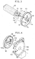
- the other end of the reel 32 projects outside of the side wall 30b and is connected to an EA mechanism 48 and a locking mechanism 50.
- the other end of the reel 32 is provided with a pair of grooves 72, 72 retaining pawls 80, 80 described later, a shaft portion 70 piercing a pawl spring 110 described later, and a spring seat 71 whereby one end of the pawl spring 110 is hooked and stopped.
- the EA mechanism 48 comprises a roll 52 which is a steel band and is formed spiral and accommodated in a roll casing 54.
- the roll casing 54 is fixed to the side wall 30b.
- An outer end 52a of the roll 52 projects outside the casing 54 as shown in Fig. 5 and secured to the side wall 30b by a rivet 56.
- the revote 56 also fixes the roll casing 54 to the side wall 30b.
- An inner end 52b of the roll 52 is inserted into a groove 62 formed in a ring-like lock base 60 and is thus secured.
- the lock base 60 is prevented from rotating by the roll inner end 52b.
- the shaft portion 70 of the reel 32 is inserted into a central hole 64 of the lock base 60.
- the lock base 60 is provided with a annular step 66 along the periphery thereof.
- the annular step 66 has internal teeth 68 on the inner periphery thereof.
- a pair of pawls 80 are arranged inside the annular step 66.
- the pawls 80 engage the grooves 72 formed in the shaft portion 70 of the reel 32, respectively, in such a manner that the pawls 80 are slidable in directions of allows Y 1 of Fig. 5a.
- Each pawl 80 has external teeth 84 formed in the outer periphery thereof. The external teeth 84 are engageable with some of the internal teeth 68 of the lock base 60.
- the roll casing 54 has a circular opening 74 through which pins 82 projecting from the pawls 80 pass to be inserted into pin guide slits 92 of the lock gear 90.
- the guide slits 92 extend diagonally to the radial direction of the lock gear 90.
- the lock gear 90 is arranged outside of the roll casing 54 and is provided with a boss 96.
- the boss 96 has a central hole 94 at the center thereof, into which the shaft portion 70 of the reel 32 is inserted.
- the lock gear 90 has a axial pin 98 projecting therefrom which fits in an axial hole 102 of a flywheel 100 for activating the locking action.
- the flywheel 100 has a projecting pin 104.
- a hook spring 106 consisting of a coil spring is disposed between the projecting pin 104 and a spring seat 97 of the lock gear 90.
- the hook spring 106 biases the flywheel 100 about the axial pin 98 in the direction of F 1 shown in Fig. 4.
- the flywheel 100 has a tooth 100a which is engageable with internal teeth 132 of a cover 130 described later. As the flywheel 100 is biased in the direction F 1 , the tooth 100a is normally spaced apart from the internal teeth 132.
- the pawl spring 110 is fitted onto the shaft portion 70 of the reel 32.
- the spring ends 112, 112 projecting radially from the pawl spring 110 are stopped by the spring seat 71 of the reel 32 and a spring seat 91 of the lock gear 90.
- the pawl spring 110 biases the lock gear 90 in a direction of S 1 shown in Fig. 3.
- the pins 82 of the pawls 80 inserted in the guide slit 92 of the lock gear 90 are positioned at inside ends in the corresponding guide slits 92 i.e. the nearest position to the boss 96.
- the external teeth 84 of the pawls 80 are spaced apart from the internal teeth 68 of the lock base 60.
- the flywheel 100 rotates about the pin 98 in the direction of F 1 against the hook spring 106 with rotational delay relative to the reel 32. Therefore, the tooth 100a engages the internal teeth 132 so that the lock gear 90 rotates in the direction of S 2 of Fig. 4, the pins 82 travel within the corresponding guide slits 92 to the lock gear's outer periphery side, and the pawls 80 slide in the directions of arrows Y 1 of Fig. 5a so that the external teeth 84 of the pawl 80 engage some of the internal teeth 68 of the lock base 60.
- a lever 126 of a lock activating mechanism 120 is engageable with one of external teeth 99 arranged on the outer periphery of the lock gear 90.
- the lock activating mechanism 120 comprises a weight 124 which is held in a holder 122 in such a manner that the weight 124 can tilt, and a the lever 126 which is journaled to the holder 122 and is laid on the weight 124. As acceleration exceeding a predetermined value is applied to the vehicle, the weight 126 tilts and the lever 126 is thus risen up so that the tip of the lever 126 engages one of the external teeth 99 arranged on the outer periphery of the lock gear 90, whereby the lock gear 90 is stopped from rotating.
- the pins 82 of the pawls 80 travel within the corresponding guide slits 92 to the outer periphery side of the lock gear 90, the pawls 80 slide in the directions of arrows Y 1 , and the external teeth 84 engage some of the internal teeth 68 of the lock base 60.
- the lock gear 90 and the lock activating mechanism 120 are covered by the cover 130.
- the cover 130 is fixed to the side wall 30b.
- the operation of the seat belt retractor will be described with reference to Figs. 5a, 5b, and 5c.
- the pawls 80 are spaced apart from the internal teeth 68 of the lock base 60 as shown in Fig. 5a.
- the locking mechanism 50 and the lock activating mechanism 120 are not operative so that the reel 32 is biased by the spring 40 in the webbing winding direction.
- the reel 32 rotate in the webbing unwinding direction with the spring 40 being wound.
- the webbing is loosen, the webbing is wound onto the reel 32 by the spring force of the spring 40.
- the weight 124 of the lock activating mechanism 120 tilts so that the lever 126 of the lock activating mechanism 120 engages one of the external teeth 99 of the lock gear 90, thereby locking the lock gear 90.
- the pawls 80 slide in the directions of arrows Y 1 to engage some of the internal teeth 68 of the lock base 60, thereby preventing the reel 32 from rotating.
- the aforementioned steel roll 52 does not deform so that the lock base 60 does not rotate.
- the lever 126 moves apart from the external teeth 99 of the lock gear 90 to allow the lock gear 90 to rotate freely.
- the pawls 80 travel back in directions opposite to the directions of arrows Y 1 to move apart from the internal teeth 68 of the lock base 60, thereby allowing the reel 32 to rotate freely. In this way, the seat belt retractor is returned to the normal state.
- the flywheel 100 rotates in a direction of F 2
- the lock gear 90 rotates in a direction of S 2
- pawls 80 slide in the directions of arrows Y 1 to engage some of the internal teeth 68 of the lock base 60, thereby locking the reel 32.
- the external teeth 84 of the pawls 80 and the internal teeth 68 of the lock base 60 are separated from each other. In this way, the seat belt retractor is returned to the normal state.
- the webbing is loaded with significantly large tension by the occupant being moved forward due to the acceleration so that extremely large torque is applied to the lock base 60 from the reel 32 through the pawls 80.
- the steel roll 52 plastically deforms so as to be reversely rolled up from the inner end as shown in Fig. 5b. Because of the plastic deformation of the roll 52, the reel 32 gradually rotates so as to unwind the webbing, thereby softening impact acting on the occupant by the webbing. As the steel roll 52 is reversely rolled up completely as shown in Fig. 5c, the rotation of the reel 32 is stopped and the webbing is prevented from being further unwound.
- the seat belt retractor of the present invention has advantages that the structure is simpler and more compact than the conventional retractor with EA mechanism and that it has stable load characteristic because of less friction of the EA load generating portion.
Landscapes
- Engineering & Computer Science (AREA)
- Mechanical Engineering (AREA)
- Automotive Seat Belt Assembly (AREA)
Applications Claiming Priority (2)
| Application Number | Priority Date | Filing Date | Title |
|---|---|---|---|
| JP10001002A JPH11192923A (ja) | 1998-01-06 | 1998-01-06 | シートベルトリトラクタ |
| JP100298 | 1998-01-06 |
Publications (2)
| Publication Number | Publication Date |
|---|---|
| EP0928722A2 true EP0928722A2 (de) | 1999-07-14 |
| EP0928722A3 EP0928722A3 (de) | 2002-08-07 |
Family
ID=11489389
Family Applications (1)
| Application Number | Title | Priority Date | Filing Date |
|---|---|---|---|
| EP98124298A Withdrawn EP0928722A3 (de) | 1998-01-06 | 1998-12-21 | Sicherheitsgurtaufroller |
Country Status (3)
| Country | Link |
|---|---|
| US (1) | US6042042A (de) |
| EP (1) | EP0928722A3 (de) |
| JP (1) | JPH11192923A (de) |
Families Citing this family (7)
| Publication number | Priority date | Publication date | Assignee | Title |
|---|---|---|---|---|
| JP4559666B2 (ja) * | 2001-07-11 | 2010-10-13 | 株式会社東海理化電機製作所 | ウエビング巻取装置 |
| DE20208319U1 (de) * | 2002-05-28 | 2002-10-10 | Trw Repa Gmbh | Gurtaufroller für einen Fahrzeug-Sicherheitsgurt |
| CN100422002C (zh) * | 2005-01-20 | 2008-10-01 | 株式会社东海理化电机制作所 | 安全带卷绕装置 |
| JP4632302B2 (ja) * | 2005-03-22 | 2011-02-16 | タカタ株式会社 | シートベルトリトラクタおよびこれを備えたシートベルト装置 |
| CN101077705B (zh) * | 2006-05-25 | 2012-09-05 | 奥托立夫开发公司 | 安全带上防止锁定织带的装置 |
| JP4758967B2 (ja) * | 2007-05-25 | 2011-08-31 | オートリブ ディベロップメント エイビイ | シートベルトのウェビングロッキング防止装置 |
| AU2007359899B2 (en) | 2007-10-12 | 2013-09-05 | Latchways Plc | Rotational energy absorber and fall arrest system |
Citations (1)
| Publication number | Priority date | Publication date | Assignee | Title |
|---|---|---|---|---|
| JPH08127313A (ja) | 1994-09-07 | 1996-05-21 | Takata Kk | シートベルト巻取装置 |
Family Cites Families (7)
| Publication number | Priority date | Publication date | Assignee | Title |
|---|---|---|---|---|
| JPS5619245U (de) * | 1979-07-19 | 1981-02-20 | ||
| GB2294630B (en) * | 1994-11-07 | 1998-10-21 | Sungwoo Corp | Seat belt webbing lock apparatus and assembly therefor |
| JP2875505B2 (ja) * | 1995-10-16 | 1999-03-31 | 株式会社東海理化電機製作所 | ウエビング巻取装置 |
| CA2237718C (en) * | 1995-11-30 | 2002-01-29 | Toyota Jidosha Kabushiki Kaisha | Webbing take-up device |
| US5618006A (en) * | 1996-02-23 | 1997-04-08 | Trw Vehicle Safety Systems Inc. | Seat belt retractor with energy management |
| DE29614587U1 (de) * | 1996-08-22 | 1996-12-19 | Trw Repa Gmbh | Kraftbegrenzer für ein Sicherheitsgurtsystem |
| DE29708493U1 (de) * | 1997-05-13 | 1997-09-11 | Trw Repa Gmbh | Gurtaufroller mit integriertem Kraftbegrenzer |
-
1998
- 1998-01-06 JP JP10001002A patent/JPH11192923A/ja active Pending
- 1998-12-18 US US09/215,536 patent/US6042042A/en not_active Expired - Fee Related
- 1998-12-21 EP EP98124298A patent/EP0928722A3/de not_active Withdrawn
Patent Citations (1)
| Publication number | Priority date | Publication date | Assignee | Title |
|---|---|---|---|---|
| JPH08127313A (ja) | 1994-09-07 | 1996-05-21 | Takata Kk | シートベルト巻取装置 |
Also Published As
| Publication number | Publication date |
|---|---|
| EP0928722A3 (de) | 2002-08-07 |
| US6042042A (en) | 2000-03-28 |
| JPH11192923A (ja) | 1999-07-21 |
Similar Documents
| Publication | Publication Date | Title |
|---|---|---|
| JPS6111085Y2 (de) | ||
| US6739541B2 (en) | Seat belt retractor with load limiting | |
| EP1488968B1 (de) | Sicherheitsgurtaufroller | |
| EP1468883A1 (de) | Sicherheitsgurtaufroller | |
| EP0297537A2 (de) | Gurtaufroller | |
| US6648260B2 (en) | Selectable load limiting seat restraint retractor | |
| JP2002127870A (ja) | ウエビング巻取装置 | |
| US6578786B2 (en) | Seat belt retractor with load absorbing mechanism | |
| US3961761A (en) | Storage device for a safety belt | |
| EP2184210A2 (de) | Sicherheitsgurtaufroller und Sicherheitsgurtvorrichtung | |
| US6042042A (en) | Seat belt retractor | |
| JPH037234Y2 (de) | ||
| JPH1035411A (ja) | シートベルト用リトラクター | |
| EP1494898B1 (de) | Sicherheitsgurtaufroller | |
| US6412875B1 (en) | Seatbelt system | |
| CN113119905A (zh) | 安全带卷收器 | |
| US6863234B2 (en) | Seatbelt retractor | |
| JP4006827B2 (ja) | シートベルトリトラクタ | |
| CN215322445U (zh) | 安全带卷收器 | |
| JP2003341473A (ja) | シートベルト用リトラクター | |
| JP3553219B2 (ja) | ウエビング巻取装置 | |
| US20040113008A1 (en) | Seatbelt retractor of an automobile | |
| JP7449303B2 (ja) | 補助スプールロックシステムを備えるシートベルトリトラクタ | |
| JPH11105671A (ja) | シートベルト用リトラクター | |
| JP4118667B2 (ja) | ウエビング巻取装置 |
Legal Events
| Date | Code | Title | Description |
|---|---|---|---|
| PUAI | Public reference made under article 153(3) epc to a published international application that has entered the european phase |
Free format text: ORIGINAL CODE: 0009012 |
|
| AK | Designated contracting states |
Kind code of ref document: A2 Designated state(s): AT BE CH CY DE DK ES FI FR GB GR IE IT LI LU MC NL PT SE |
|
| AX | Request for extension of the european patent |
Free format text: AL;LT;LV;MK;RO;SI |
|
| PUAL | Search report despatched |
Free format text: ORIGINAL CODE: 0009013 |
|
| AK | Designated contracting states |
Kind code of ref document: A3 Designated state(s): AT BE CH CY DE DK ES FI FR GB GR IE IT LI LU MC NL PT SE |
|
| AX | Request for extension of the european patent |
Free format text: AL;LT;LV;MK;RO;SI |
|
| RIC1 | Information provided on ipc code assigned before grant |
Free format text: 7B 60R 22/405 A, 7B 60R 22/28 B, 7B 60R 22/34 B |
|
| AKX | Designation fees paid | ||
| REG | Reference to a national code |
Ref country code: DE Ref legal event code: 8566 |
|
| STAA | Information on the status of an ep patent application or granted ep patent |
Free format text: STATUS: THE APPLICATION IS DEEMED TO BE WITHDRAWN |
|
| 18D | Application deemed to be withdrawn |
Effective date: 20030208 |