EP0926842A2 - Verfahren zur Sendeleistungsregelung, Basisstation und Kommunikationsendgerät - Google Patents
Verfahren zur Sendeleistungsregelung, Basisstation und Kommunikationsendgerät Download PDFInfo
- Publication number
- EP0926842A2 EP0926842A2 EP19980124543 EP98124543A EP0926842A2 EP 0926842 A2 EP0926842 A2 EP 0926842A2 EP 19980124543 EP19980124543 EP 19980124543 EP 98124543 A EP98124543 A EP 98124543A EP 0926842 A2 EP0926842 A2 EP 0926842A2
- Authority
- EP
- European Patent Office
- Prior art keywords
- power
- control
- transmission
- value
- transmission power
- Prior art date
- Legal status (The legal status is an assumption and is not a legal conclusion. Google has not performed a legal analysis and makes no representation as to the accuracy of the status listed.)
- Withdrawn
Links
Images


Classifications
-
- H—ELECTRICITY
- H04—ELECTRIC COMMUNICATION TECHNIQUE
- H04W—WIRELESS COMMUNICATION NETWORKS
- H04W52/00—Power management, e.g. TPC [Transmission Power Control], power saving or power classes
- H04W52/04—TPC
- H04W52/18—TPC being performed according to specific parameters
- H04W52/22—TPC being performed according to specific parameters taking into account previous information or commands
- H04W52/221—TPC being performed according to specific parameters taking into account previous information or commands using past power control commands
-
- H—ELECTRICITY
- H04—ELECTRIC COMMUNICATION TECHNIQUE
- H04W—WIRELESS COMMUNICATION NETWORKS
- H04W52/00—Power management, e.g. TPC [Transmission Power Control], power saving or power classes
- H04W52/04—TPC
- H04W52/30—TPC using constraints in the total amount of available transmission power
- H04W52/36—TPC using constraints in the total amount of available transmission power with a discrete range or set of values, e.g. step size, ramping or offsets
- H04W52/367—Power values between minimum and maximum limits, e.g. dynamic range
Definitions
- the present invention relates to a transmission power control method, a base station apparatus and a communication terminal and more particularly, is preferably applied to a cellular radio communication system.
- an area in which communication service is provided is divided into cells of a desired size, a base stations is located in each of the cells as a fixed station, and a communication terminal as a mobile station radio-communicates with the base station whose communication condition is considered to be the best.
- the base station and the communication terminal monitor a reception power (or quality of the reception power) each other, and form a feedback loop by notifying the monitoring result to each other, to perform transmission power control for communication with the minimum transmission power.
- the cellular radio communication system enables communication to be efficiently performed with the minimum transmission power, so that the power consumption can be reduced as compared with the case where the communication is performed with fixed power. Therefore, a communication terminal can be particularly provided with a distinctive advantage that a lifetime of a battery can be prolonged.
- a cellular radio communication system is described as follows.
- Fig. 1, 1 generally represents a cellular radio communication system of the time division multiple access (TDMA) method, which performs the communication by connecting a base station 2 to a communication terminal 3 with a radio circuit.
- the base station 2 comprises a reception unit 4, a control unit 5 and a transmission unit 6, and the communication terminal 3 also comprises a reception unit 7, a control unit 8 and a transmission unit 9.
- the base station 2 and the communication terminal 3 use these circuit blocks to communicate with each other.
- the reception unit 4 of the base station 2 receives a transmission signal from the communication terminal 3, demodulates the incoming transmission data and detects the control data, included in the transmission signal, for power control, and transmits the detected control data to the control unit 5. Further, the reception unit 4 detects a signal-to-interference wave power ratio C/I (the ratio of the desired wave power and the interference wave power) of the transmission signal from the communication terminal 3, and also transmits the detected signal-to-interference wave power ratio C/I to the control unit 5.
- C/I the ratio of the desired wave power and the interference wave power
- the control unit 5 generates a power control signal for controlling the transmission power of the local station based on the control data from the reception unit 4, and sends it out to the transmission unit 6. Moreover, the control unit 5 generates control data for controlling the transmission power of the communication terminal 3 based on the signal-to-interference wave power ratio C/I from the reception unit 4, and also sends it out to the transmission unit 6.
- the transmission unit 6 controls the transmission power of the local station based on the power control signal supplied from the control unit 5, and inserts the control data supplied from the control unit 5 into the transmission data in order to generate a transmission signal, and sends the transmission signal to the communication terminal 3.
- the reception unit 7 of the communication terminal 3 receives the transmission signal from the base station 2, demodulates the incoming transmission data and detects the control data, included in the transmission signal, for power control, and transmits the detected control data to the control unit 8. Further, the reception unit 7 detects a signal-to-interference wave power ratio C/I of the transmission signal from the base station 2, and transmits the detected signal-to-interference wave power ratio C/I to the control unit 8.
- the control unit 8 generates a power control signal for controlling the transmission power of the local station based on the control data from the reception unit 7, and sends it out to the transmission unit 9. Moreover, the control unit 8 generates control data for controlling the transmission power of the base station 2 based on the signal-to-interference wave power ratio C/I from the reception unit 7, and also sends it out to the transmission unit 9.
- the transmission unit 9 controls the transmission power of the local station based on the power control signal received from the control unit 8, and inserts the control data supplied from the control unit 8 into transmission data in order to generate a transmission signal, and sends the transmission signal to the base station 2.
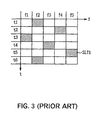
- frequency hopping is performed to randomly change the frequency channel to be used, according to a predetermined pattern for every slot, so that the effects of the interference waves from other communications can be reduced.
- the base station 2 and the communication terminal 3 detect the signal-to-interference wave power ratio C/I of the transmission signal from each other, and notify the control data of the transmission power according to the detection result to each other, thereby to control the transmission power.
- the flowchart of Fig. 2 is used to explain the transmission power control procedure in the control unit 8, which controls the transmission power of the communication terminal 3 based on the control data for the power control supplied from the base station 2.
- the control unit 8 of the communication terminal 3 begins with the starting step RT1, and moves to the step SP1.
- the control unit 8 first accepts a power control command from the reception unit 7, and moves to the step SP2.
- the control unit 8 determines whether the power control command is a power-up command, which means increase of the transmission power, or not. If the positive result is obtained, the result means a power-up command is accepted, then the control unit 8 moves to the step SP3.
- the control unit 8 determines whether the current transmission power is smaller than the maximum transmission power or not. If the positive result is obtained, the result means there is room to further increase the transmission power, and the control unit 8 moves to the step SP4. On the other hand, if the negative result is obtained in the step SP3, the result means that the current transmission power has already reached the maximum transmission power and the transmission power cannot be increased any more, and the control unit 8 returns to the step SP1 again while maintaining this state.
- the control unit 8 sends out the power-up command to the transmission unit 9 to increase the transmission power by a predetermined level with the transmission unit 9, and returns to the step SP1 again.
- the result means a power-down command, not a power-up command, has been accepted, and the control unit 8 moves to the step SP5.
- the control unit 8 determines whether the current transmission power is larger than the minimum transmission power or not. The positive result is obtained, the result means there is room to further lower the transmission power, the control unit 8 moves to the step SP6. In the step SP6, the control unit 8 sends out the power-down command to the transmission unit 9 to lower the transmission power by a predetermined level with the transmission unit 9, and returns to the step SP1 again.
- the control unit 8 returns to the step SP1 again while maintaining this state.
- the base station 2 and the communication terminal 3 monitor the reception power (or quality of the reception power) each other, and notify the monitoring result to each other, to form a feedback loop for performing the transmission power control.
- a transmission error can occur during the transmission of the monitoring result to each other through the feedback loop, so that the power-up command and the power-down command are inverted respectively.
- the communication terminal 3 when a power-up command is repeatedly sent from the base station 2 regardless of the current transmission power being the maximum because the base station 2 and the communication terminal 3 are distant from each other, if a power-down command is sent due to a transmission error, the transmission power is lowered according to the power-down command even though the transmission power is desired to be increased because the transmission power is obviously insufficient. As a result, the cellular radio communication system 1 has a problem that communication quality cannot be maintained between the base station 2 and the communication terminal 3.
- the communication terminal 3 when a power-down command is repeatedly sent from the base station 2 regardless of the current transmission power being the minimum because the distance between the base station 2 and the communication terminal 3 has become shorter, if a power-up command is sent due to a transmission error, the transmission power is increased according to the power-up command even though the transmission power is desired to be lowered because the transmission power is obviously sufficient. As a result, the communication with an optimum transmission power according to the distance between the base station 2 and the communication terminal 3 cannot be performed, thus the cellular radio communication system 1 has problems that an increase in the power consumption is caused and an interference wave to other channels occurs.
- the frequency hopping (FH) is performed to randomly change the frequency channel to be used according to a predetermined pattern (diagonally shaded portions) for each slot, as shown in Fig. 3.
- a predetermined pattern diagonally shaded portions
- the communication terminal 3 lowers the transmission power according to the accidental power-down command, the transmission power is short again in the next frequency hopping. Accordingly, since it is possible that a power-down command due to some error is sent, the communication terminal 3 has a problem that communication quality cannot be maintained if the transmission power is easily lowered.
- an object of the present invention is to provide a transmission power control method, a base station apparatus and a communication terminal, which always enable the transmission with an optimum transmission power.
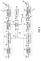
- Fig. 4 in which the portions corresponding to Fig. 1 are assigned the same symbols, 30 represents a cellular radio communication system of the TDMA method as a whole, and communication is performed by connecting a base station apparatus 31 to a communication terminal 32 with a wireless circuit.
- the reception unit 4 of the base station 31 receives a transmission signal from the communication terminal 32, demodulates the incoming transmission data and detects the control data, included in the transmission signal, for the power control, and transmits the detected control data to a control unit 33. Further, the reception unit 4 detects a signal-to-interference wave power ratio C/I of the transmission signal from the communication terminal 32, and also transmits the detected signal-to-interference wave power ratio C/I to the control unit 33.
- the control unit 33 generates a power control signal for controlling the transmission power of the local station based on the control data from the reception unit 4, and sends it out to the transmission unit 6. Moreover, the control unit 33 generates control data for controlling the transmission power of the communication terminal 32 based on the signal-to-interference wave power ratio C/I from the reception unit 4, and also sends it out to the transmission unit 6.
- the transmission unit 6 controls the transmission power of the local station based on the power control signal received from the control unit 33, generates a transmission signal by inserting the control data supplied from the control unit 33 into transmission data, and sends it out to the communication terminal 32.
- the reception unit 7 of the communication terminal 32 receives the transmission signal from the base station 31, and demodulates the incoming transmission data and detects the control data for the power control included in the transmission signal, and transmits the detected control data to a control unit 34. Further, the reception unit 7 detects a signal-to-interference wave power ration C/I of the transmission signal from the base station 31, and transmits the detected signal-to-interference wave power ratio C/I to the control unit 34.
- the control unit 34 generates a power control signal for controlling the transmission power of the local station based on the control data from the reception unit 7, and sends it out to the transmission unit 9. Moreover, the control unit 34 generates control data for controlling the transmission power of the base station 31 based on the signal-to-interference wave power ratio C/I from the reception unit 7, and also sends it out to the transmission unit 9.
- the transmission unit 9 controls the transmission power of the local station based on the power control signal supplied from the control unit 34, generates a transmission signal by inserting the control data supplied from the control unit 34 into the transmission data, and sends it out to the base station 31.
- the frequency hopping (FH) is performed to randomly change the frequency channel to be used according to a predetermined pattern for every slot, to reduce the effect of the interference waves from other communications.
- the base station 31 and the communication terminal 32 detect the signal-to-interference wave power ratio C/I of the transmission signal from each other, and notify the control data of the transmission power according to the detection result to each other, to control the transmission power.
- the base station 31 and the communication terminal 32 are provided with the new control units 33 and 34 which perform different control from the control units 5 and 8 of the cellular radio communication system 1, and counters 35 and 36 are connected to the control units 33 and 34 respectively.
- the reception unit 7, the control unit 34, and the transmission unit 9 of the communication terminal 32 are described as follows. Since the circuit constructions of the base station 31 and the communication terminal 32 are the same, the description of the reception unit 4, the control unit 33, and the transmission unit 6 of the base station 31 is omitted.
- the received signal S1 received first via an antenna 10 is amplified and then, it is subjected to a frequency conversion process to extract a base band signal.
- the base band signal is subjected to a filtering process and thereafter an analog-to-digital conversion process, so that a received signal S2 is generated and sent out to a demodulating circuit 12.
- the demodulating circuit 12 applies a predetermined demodulation process to the received signal S2, and sends out the resultant group of received symbols S3 to a demultiplexer 13. Moreover, the demodulating circuit 12 detects the signal-to-interference wave power ratio C/I of the received signal S2 for every slot, and sends out detection data S4 representing the detected signal-to-interference wave power ratio C/I to the control unit 34.
- the demultiplexer 13 extracts a control symbol S5 for the power control from the supplied group of received symbols S3, and sends out the control symbol S5 to the control unit 34.
- a control symbol S5 for the power control from the supplied group of received symbols S3, and sends out the control symbol S5 to the control unit 34.
- one symbol is inserted into each slot of the control symbol S5 for the power control.
- the demultiplexer 13 sends out a received symbol S6 which remains after extracting the control symbol S5, to a channel decoder 14.
- the channel decoder 14 applies a predetermined symbol demodulation process to the received symbol S6 to restore a received data bit S7 from the received symbol S6, and outputs the received data bit S7 to an audio signal processing circuit (not shown) in the subsequent stage.
- the control unit 34 detects the control data for the transmission power instructed by the base station 31, based on the control symbol S5 supplied from the demultiplexer 13, and generates a power control signal S20 according to the detected data in order to send it out to the transmission unit 9. Moreover, the control unit 34 generates control data for the transmission power of the base station 31 based on the signal-to-interference wave power ratio C/I shown by the supplied detected data S4, and generates a control symbol S9 representing the control data so as to output it to the transmission unit 9.
- the control unit 34 compares the signal-to-interference wave power ratio C/I with a first threshold value, and generates control data for lowering the transmission power by one dB if the ratio C/I is greater than the first threshold value. Further, the control unit 34 compares the signal-to-interference wave power ratio C/I with a second threshold value, and generates control data for increasing the transmission power by one dB if the ratio C/I is smaller than the second threshold value. Thus, the control unit 34 generates the control symbol S9 based on the control data. In addition, since the control unit 34 detects the signal-to-interference wave power ratio C/I for every slot, the control unit 34 generates one control symbol S9 for one slot.
- a transmission data bit S10 to be sent which is supplied from the audio signal processing unit (not shown) is first input to a channel encoder 15.
- the channel encoder 15 performs a predetermined coding process to generate a transmission symbol S11, and sends it out to a multiplexer 16.
- the multiplexer 16 receives the control symbol S9 from the control unit 34, and also receives the transmission symbol S11 from the channel encoder 15.
- the multiplexer 16 generates a transmission symbol S12 by inserting the control symbol S9 into a predetermined position of the transmission symbol S11, and sends it out to a modulating circuit 17. Incidentally, since one control symbol S9 is generated for one slot, one control symbol S9 is inserted for one slot.
- the modulating circuit 17 applies a predetermined modulation process to the transmission symbol S12 in order to generate a transmission signal S13, and sends it out to a variable gain amplifier 18.
- the variable gain amplifier 18 receives a power control signal S20 from the control unit 34, amplifies the transmission signal S13 with a gain value based on the power control signal S20 in order to generate a transmission signal S14 of the transmission power instructed by the base station 31, and sends it out to a transmission circuit 19.
- the transmission circuit 19 applies a filtering process to the transmission signal S14 and then a digital-to-analog conversion process, and after applying a high-frequency process such as frequency conversion to it, amplifies it to a transmission signal S15 of a predetermined power, and sends it out via an antenna 20.
- the power control signal S20 supplied from the control unit 34 consists of a power-up command or a power-down command for controlling the power-up or the power-down of the transmission power.
- the transmission unit 9 controls the gain of the variable gain amplifier 18 based on the power control signal S20, to increase the transmission power by one dB with one power-up command, or to lower the transmission power by one dB with one power-down command.
- control unit 34 controls the amplification operation of the variable gain amplifier 18 and monitors the gain value based on the power control signal S20 so as to always keep track of the current transmission power. Accordingly, the control unit 34 increases the transmission power if the current transmission power is smaller than the maximum transmission power and the instruction of the control symbol S5 provided from the demultiplexer 13 is a power-up command. On the other hand, the control unit 34 lowers the transmission power if the current transmission power is greater than the minimum transmission power and the instruction of the control symbol S5 is a power-down command.
- the control unit 34 counts the number of receptions of the received control symbol S5 by the counter 36, and stops supplying the power control signal S20 generated based on the control symbol S5 to the transmission unit 9.
- the control unit 34 does not immediately lower the transmission power according to the power-down command, but it first counts down the count value of the counter 36 by "one".
- a power-up command is repeatedly supplied from the base station 31 when the communication terminal 32 is lack of transmission power.
- the communication terminal 32 cannot increase the transmission power when the current transmission power has already reached the maximum transmission power, so that the count value of the counter 36 is incremented by the number of times the power-up command is supplied.
- the communication quality is inconveniently degraded.
- the communication terminal 32 since a power-down command can be supplied due to a transmission error or the like, the communication terminal 32 does not immediately lower the transmission power according to the power-down command. It is not until the communication terminal 32 recognizes that this is not the power-down command supplied due to an error or the like, but the power-down command indicating such the communication environment that the transmission power can be lowered when the power-down command is supplied several times, that the transmission power is lowered.
- the control unit 34 lowers the transmission power by one dB according to the power-down command. That is, by providing a difference between the number of counts based on the power-up command and the number of counts by count-down based on the power-down command, the control unit 34 executes the control of the transmission power with a hysteresis characteristic.
- control unit 34 does not lower the transmission power until the count value reaches "M" even if a power-down command due to an error or the like is supplied instead of a power-up command. Therefore, the control unit 34 does not immediately lower the transmission power even if a power-down command due to an error or the like is supplied when power-up commands are continuously supplied, whereby the communication condition can be prevented from being deteriorated.
- control unit 34 controls the amplification operation of the variable gain amplifier 18 based on the count value of the counter 36 in consideration of the safety factor so that the control unit 34 does not lower the transmission power until it recognizes that the communication condition becomes good and a sure power-down command is supplied, whereby the communication quality between the base station 31 and the communication terminal 32 can be maintained.
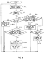
- the control unit 34 of the communication terminal 32 begins with the starting step RT2, and moves to the step SP11.
- the control unit 34 first receives the control symbol S5 as a power control command from the demultiplexer 13 of the reception unit 7, and moves to the step SP12.
- the control unit 34 determines whether or not the control data for the transmission power instructed by the base station 31 is a power-up command which means the increase of the transmission power, based on the control symbol S5. If the positive result is obtained, the result means a power-up command has occurred, then the control unit 34 moves to the step SP13.
- the control unit 34 determines whether the current transmission power is smaller than the maximum transmission power or not. If the positive result is obtained, the result means that the current transmission power is smaller than the maximum transmission power and there is room to further increase the transmission power, then the control unit 34 moves to the step SP14.
- the control unit 34 sends out the power control signal S20 generated based on the control symbol S5 to the transmission unit 9, to increase the transmission power by one dB with the transmission unit 9, and returns to the step SP11 again.
- the control unit 34 increments the count value of the counter 36 and moves to the step SP15.
- the control unit 34 determines whether the count value of the counter 36 has reached "N" (in this example, "10") or not. If the negative result is obtained, the result means the count value of the counter 36 has not been counted up to "N" as yet. At this time, the control unit 34 moves to the step SP16.
- control unit 34 increments the count value of the counter 36 by the number of supplied power-up commands, and returns to the step SP11 again.
- the control unit 34 returns to the step SP11 again.
- the control unit 34 moves to the step SP17.
- the control unit 34 determines whether the current count value of the counter 36 indicates a count value greater than "M" or not. If the positive result is obtained, the result means that the current value of the counter 36 indicates a count value greater than "M". That is, a power-up command has been supplied a plurality of times even though the transmission power has already reached the maximum transmission power and the plurality of times have been already counted more than the count value "M". At this time, the control unit 34 does not lower the transmission power, but it decreases the count value of the counter 36 by one and returns to the step SP11 again.
- the result means the current count value of the counter 36 is "M". That is, the current count value has reached "M” as a result of decreasing the count value of the counter 36 according to each occurrence of power-down commands, and at this time the control unit 34 moves to the step SP19.
- the control unit 34 determines whether the current transmission power is greater than the minimum transmission power or not. If the negative result is obtained, the result means that a power-down command is supplied even though the current transmission power has already reached the minimum transmission power and the transmission power cannot be lowered any more. At this time, the control unit 34 returns to the step SP11 again while maintaining this state.
- the control unit 34 moves to the step SP20.
- the control unit 34 sends out the power control signal S20 generated based on the control symbol S5 to the transmission unit 9, lowers the transmission power by one dB with the variable gain amplifier 18 of the transmission unit 9, and moves to the step SP21.
- control unit 34 resets the count value of the counter 36 from "M" to "0" in order to prepare for controlling the transmission power according to the next new power control command, and returns to the step SP11 again so as to complete the process.
- the communication terminal 32 counts up the number of times the power-up command is supplied by the counter 36 while it cannot increase the transmission power any more.
- a power-down command is supplied once thereafter, it plausibly seems a power-down command due to an error or the like.
- the communication quality is degraded if the communication terminal 32 immediately lowers the transmission power according to such wrong power-down command, and therefore the communication terminal 32 first counts down the count value of the counter 36 by one rather than actually lowering the transmission power.
- the communication terminal 32 counts down the count value of the counter 36 by the plurality of times. Then, if the count value of the counter reaches "M", the communication terminal 32 determines that the power-down command is not a power-down command due to an error or the like because the power-down command has been continuously supplied a plurality of times. At this time, the transmission power can be lowered according to the power-down command.
- the control unit 34 by controlling the transmission power so that the transmission power is not lowered until the control unit 34 recognizes a real power-down command based on the count value of the counter 36, control of the transmission power based on a wrong power-down command due to a transmission error or the like is eliminated, so that the transmission signal S15 can always be sent out to the base station 31 with the optimum transmission power.
- the control unit 34 controls the transmission power not to be lowered until a power-down command is supplied a predetermined number of times after a power-up command has supplied a plurality of times, the transmission power can be lowered only when a real power-down command is surely recognized, and thus the transmission can always be performed with the optimum transmission power.
- the count value "N" of the counter 36 as counting means is set to “10" at maximum, and the count value “M” as a reference for lowering the transmission power is set to "5" by the control unit 34 as control means.
- the present invention is not limited thereto, but the count value can be set to a count value with arbitrary hysteresis characteristic according to the communication environment, such as setting the count value "N” to "5", and setting the count value "M" to "0".
- a hysteresis characteristic is provided by setting the count value "N" of the counter 36 to “10” at maximum, and setting the count value “M” as a reference for lowering the transmission power to "5" by the control unit 34.
- the present invention is not limited thereto, but no hysteresis characteristic can be given by setting the count value "N” of the counter 36 to "10” at maximum, and setting the count value "M” as a reference for lowering the transmission power to "10". In this case, since the transmission power is not easily lowered, the communication quality is degraded more difficultly.
- the present invention is not limited thereto, but the present invention can be applied to the transmission control method for a power-up command in the case where a power-down command is supplied a plurality of times when the transmission power has already reached the minimum transmission power.
- the communication terminal 32 can obtain the same effect by changing only the control method of the control unit 34.
- a transmission power control method in which a control signal for controlling the transmission power is transmitted at the transmission side, and the transmission power is controlled based on the received control signal at the reception side; with the power value of the transmission power having reached the limit value of a power control range, if the instructions of the received control signal are to control the power value in the direction of allowing it to exceed the power control range, the number of receptions of the control signal is counted, and if the instructions of the control signal received thereafter are to control the power value in the direction of not allowing it to exceed the power control range, the count value of the number of receptions is decreased, and it is not until the count value reaches a predetermined value that the power value is controlled in the direction of not allowing it to exceed the power control range; whereby the transmission power is not immediately lowered even if an error or the like causes the reception of the control signal controlling the power value in a wrong direction, and it is not until the normal control signal is received a predetermined number of times that the transmission power can be
- a base station apparatus which controls the transmission power of a transmission signal based on the control signal sent from a communication terminal as a mobile station, by providing receiving means for receiving the control signal; counting means for counting the number of receptions of the control signal; control means for counting the number of receptions of the control signal by the counting means if the instructions of the received control signal are to control the power value of the transmission power in the direction of allowing it to exceed a power control range, with the power value having reached the limit value of the power control range, decreasing the count value of the number of receptions if the instructions of the control signal received thereafter are to control the power value in the direction of not allowing it to exceed the power control range, and not controlling the power value in the direction of not allowing it to exceed the power control range until the count value reaches a predetermined value; and transmitting means for performing the transmission to the mobile station with the transmission power controlled by the control means, the transmission power is not immediately lowered even if an error or the like causes the reception of the control signal controlling the power value in
- a communication terminal which controls the transmission power of a transmission signal based on the control signal sent from a base station apparatus as a fixed station, by providing receiving means for receiving the control signal; counting means for counting the number of receptions of the control signal; control means for counting the number of receptions of the control signal by the counting means if the instructions of the received control signal are to control the power value of the transmission power in the direction of allowing it to exceed a power control range, with the power value having reached the limit value of the power control range, decreasing the count value of the number of receptions if the instructions of the control signal received thereafter are to control the power value in the direction of not allowing it to exceed the power control range, and not controlling the power value in the direction of not allowing it exceed the power control range until the count value reaches a predetermined value; and transmitting means for performing the transmission to the base station apparatus with the transmission power controlled by the control means, the transmission power is not immediately lowered even if an error or the like causes the reception of the control signal controlling the power value in
Applications Claiming Priority (2)
| Application Number | Priority Date | Filing Date | Title |
|---|---|---|---|
| JP36773297A JP3755704B2 (ja) | 1997-12-27 | 1997-12-27 | 送信電力制御方法、基地局装置及び通信端末装置 |
| JP36773297 | 1997-12-27 |
Publications (2)
| Publication Number | Publication Date |
|---|---|
| EP0926842A2 true EP0926842A2 (de) | 1999-06-30 |
| EP0926842A3 EP0926842A3 (de) | 2001-01-31 |
Family
ID=18490058
Family Applications (1)
| Application Number | Title | Priority Date | Filing Date |
|---|---|---|---|
| EP19980124543 Withdrawn EP0926842A3 (de) | 1997-12-27 | 1998-12-22 | Verfahren zur Sendeleistungsregelung, Basisstation und Kommunikationsendgerät |
Country Status (3)
| Country | Link |
|---|---|
| US (1) | US6226526B1 (de) |
| EP (1) | EP0926842A3 (de) |
| JP (1) | JP3755704B2 (de) |
Cited By (10)
| Publication number | Priority date | Publication date | Assignee | Title |
|---|---|---|---|---|
| EP1069702A2 (de) * | 1999-07-16 | 2001-01-17 | Lucent Technologies Inc. | Synchronisierung der Sendeleistungspegeleinstellungen während weichem Weiterreichen in einem drahtlosen System mittels Leistungspegelbegrenzungen |
| WO2001031808A1 (en) * | 1999-10-25 | 2001-05-03 | Motorola Limited | Reduction of transmit power in a mobile station |
| EP1122896A2 (de) * | 2000-02-02 | 2001-08-08 | Nec Corporation | Funkübertragungssystem |
| EP1134911A1 (de) | 2000-03-17 | 2001-09-19 | Alcatel | Betrieb eines zellularen Telekommunikationssystems |
| WO2001091320A1 (de) * | 2000-05-20 | 2001-11-29 | Robert Bosch Gmbh | Verfahren zur regelung der sendeleistung einer sendestation und sendestation |
| EP1175020A1 (de) * | 2000-07-20 | 2002-01-23 | Alcatel | Regelung der Sendeleistung in Abwärtsrichtung in einem zellularen Telekommunikationssystem |
| WO2002015431A2 (de) * | 2000-08-17 | 2002-02-21 | Siemens Aktiengesellschaft | Verfahren zur regelung der sendeleistung in einem funksystem |
| EP1239604A1 (de) * | 2001-03-05 | 2002-09-11 | Lucent Technologies Inc. | Überschwingungssteurung der Aufwärtsrichtungsleistung mit Berücksichtigung der Übertragungsbegrenzungen einer Mobilstation |
| EP1249941A1 (de) * | 2000-11-13 | 2002-10-16 | Mitsubishi Denki Kabushiki Kaisha | Tragbares telefon |
| EP1267499A1 (de) * | 2000-03-23 | 2002-12-18 | Huawei Technologies Co., Ltd. | Verfahren zur verhinderung einer vorwärts-leistungssättigung und einrichtung zur leistungs-steuerung in einem cdma-kommunikationssystem |
Families Citing this family (11)
| Publication number | Priority date | Publication date | Assignee | Title |
|---|---|---|---|---|
| EP1088406B1 (de) * | 1998-06-17 | 2004-04-14 | Siemens Aktiengesellschaft | Verfahren und system zur regelung der übertragungsleistung einer mobilstation eines mobilfunksystems |
| US6529482B1 (en) * | 1999-06-30 | 2003-03-04 | Qualcomm Inc. | Method and apparatus for adjusting a signal-to-interference threshold in a closed loop power control communications system |
| FI112743B (fi) | 1999-10-20 | 2003-12-31 | Nokia Corp | Menetelmä ja järjestely lähetystehon säätämiseksi sekä verkkoelementti |
| JP3389951B2 (ja) * | 2000-02-07 | 2003-03-24 | 日本電気株式会社 | Cdma移動通信システム及び該cdma移動通信システムにおける下り回線送信電力制御方法 |
| US6799045B1 (en) | 2000-11-07 | 2004-09-28 | Telefonaktiebolaget Lm Ericsson (Publ) | Reliable congestion control in a CDMA-based mobile radio commmunications system |
| US6985739B2 (en) * | 2000-12-15 | 2006-01-10 | Telefonaktiebolaget Lm Ericsson (Publ) | Admission and congestion control in a CDMA-based mobile radio communications system |
| KR100438171B1 (ko) * | 2000-12-19 | 2004-07-01 | 엘지전자 주식회사 | 기지국 송신 상태 측정 회로 |
| KR100531361B1 (ko) * | 2000-12-30 | 2005-11-28 | 엘지전자 주식회사 | Ds―cdma 시스템에서의 전력 제어 방법 |
| EP1588504B1 (de) * | 2003-01-31 | 2008-05-28 | Nokia Corporation | Ausgangsleistungsregelung für aufwärtsverbindungen mit mehreren zeitschlitzen |
| JP2005006251A (ja) | 2003-06-16 | 2005-01-06 | Oki Electric Ind Co Ltd | フィルタ装置および送信電力制御装置 |
| KR20090032270A (ko) * | 2007-09-27 | 2009-04-01 | 삼성전자주식회사 | 휴대단말기의 전원제어 장치 |
Citations (1)
| Publication number | Priority date | Publication date | Assignee | Title |
|---|---|---|---|---|
| EP0682417A2 (de) | 1994-05-12 | 1995-11-15 | Ntt Mobile Communications Network Inc. | Übertragungsleistungsregelung in der die Übertragungsleistung entsprechend der Anzahl von nacheinander empfangener Übertragungsleistungsregelungsbit gleichen Wertes eingestellt wird |
Family Cites Families (7)
| Publication number | Priority date | Publication date | Assignee | Title |
|---|---|---|---|---|
| US5333175A (en) * | 1993-01-28 | 1994-07-26 | Bell Communications Research, Inc. | Method and apparatus for dynamic power control in TDMA portable radio systems |
| JP2974274B2 (ja) * | 1994-05-12 | 1999-11-10 | エヌ・ティ・ティ移動通信網株式会社 | 送信電力制御方法および送信電力制御装置 |
| BR9611480A (pt) * | 1995-11-10 | 1999-07-13 | Ionica Int Ltd | Método e aparelho para controle de força em um sistema de telefone |
| FI100072B (fi) * | 1996-01-19 | 1997-09-15 | Nokia Mobile Phones Ltd | Menetelmä lähetystehon säätämiseksi sekä radiojärjestelmä |
| KR980007105A (ko) * | 1996-06-28 | 1998-03-30 | 김광호 | 이동국 송신전력 제어방법 |
| US5960361A (en) * | 1996-10-22 | 1999-09-28 | Qualcomm Incorporated | Method and apparatus for performing a fast downward move in a cellular telephone forward link power control system |
| JP3459866B2 (ja) * | 1997-04-22 | 2003-10-27 | 埼玉日本電気株式会社 | 符号分割多元接続方式の送信電力制御方法 |
-
1997
- 1997-12-27 JP JP36773297A patent/JP3755704B2/ja not_active Expired - Fee Related
-
1998
- 1998-12-18 US US09/216,503 patent/US6226526B1/en not_active Expired - Lifetime
- 1998-12-22 EP EP19980124543 patent/EP0926842A3/de not_active Withdrawn
Patent Citations (1)
| Publication number | Priority date | Publication date | Assignee | Title |
|---|---|---|---|---|
| EP0682417A2 (de) | 1994-05-12 | 1995-11-15 | Ntt Mobile Communications Network Inc. | Übertragungsleistungsregelung in der die Übertragungsleistung entsprechend der Anzahl von nacheinander empfangener Übertragungsleistungsregelungsbit gleichen Wertes eingestellt wird |
Cited By (21)
| Publication number | Priority date | Publication date | Assignee | Title |
|---|---|---|---|---|
| EP1069702A3 (de) * | 1999-07-16 | 2003-05-21 | Lucent Technologies Inc. | Synchronisierung der Sendeleistungspegeleinstellungen während weichem Weiterreichen in einem drahtlosen System mittels Leistungspegelbegrenzungen |
| EP1069702A2 (de) * | 1999-07-16 | 2001-01-17 | Lucent Technologies Inc. | Synchronisierung der Sendeleistungspegeleinstellungen während weichem Weiterreichen in einem drahtlosen System mittels Leistungspegelbegrenzungen |
| WO2001031808A1 (en) * | 1999-10-25 | 2001-05-03 | Motorola Limited | Reduction of transmit power in a mobile station |
| GB2355887B (en) * | 1999-10-25 | 2004-01-07 | Motorola Ltd | Reduction of transmit power in a mobile station |
| EP1122896A2 (de) * | 2000-02-02 | 2001-08-08 | Nec Corporation | Funkübertragungssystem |
| EP1122896A3 (de) * | 2000-02-02 | 2005-06-08 | Nec Corporation | Funkübertragungssystem |
| EP1134911A1 (de) | 2000-03-17 | 2001-09-19 | Alcatel | Betrieb eines zellularen Telekommunikationssystems |
| EP1267499A4 (de) * | 2000-03-23 | 2006-11-02 | Huawei Tech Co Ltd | Verfahren zur verhinderung einer vorwärts-leistungssättigung und einrichtung zur leistungs-steuerung in einem cdma-kommunikationssystem |
| EP1267499A1 (de) * | 2000-03-23 | 2002-12-18 | Huawei Technologies Co., Ltd. | Verfahren zur verhinderung einer vorwärts-leistungssättigung und einrichtung zur leistungs-steuerung in einem cdma-kommunikationssystem |
| WO2001091320A1 (de) * | 2000-05-20 | 2001-11-29 | Robert Bosch Gmbh | Verfahren zur regelung der sendeleistung einer sendestation und sendestation |
| US9008596B2 (en) | 2000-05-20 | 2015-04-14 | Ipcom Gmbh & Co. Kg | Method for regulating the transmission power of a transmitting station, and transmitting station |
| EP1175020A1 (de) * | 2000-07-20 | 2002-01-23 | Alcatel | Regelung der Sendeleistung in Abwärtsrichtung in einem zellularen Telekommunikationssystem |
| US6591113B1 (en) | 2000-07-20 | 2003-07-08 | Alcatel | Operating a cellular telecommunication system |
| EP1501207A1 (de) * | 2000-08-17 | 2005-01-26 | Siemens Aktiengesellschaft | Verfahren zur Regelung der Sendeleistung in einem Funksystem |
| US7062288B2 (en) | 2000-08-17 | 2006-06-13 | Siemens Aktiengesellschaft | Method for controlling the transmission power in a radio communication system |
| WO2002015431A3 (de) * | 2000-08-17 | 2002-05-23 | Siemens Ag | Verfahren zur regelung der sendeleistung in einem funksystem |
| WO2002015431A2 (de) * | 2000-08-17 | 2002-02-21 | Siemens Aktiengesellschaft | Verfahren zur regelung der sendeleistung in einem funksystem |
| EP1249941A1 (de) * | 2000-11-13 | 2002-10-16 | Mitsubishi Denki Kabushiki Kaisha | Tragbares telefon |
| EP1249941A4 (de) * | 2000-11-13 | 2005-01-19 | Mitsubishi Electric Corp | Tragbares telefon |
| US6829468B2 (en) | 2001-03-05 | 2004-12-07 | Lucent Technologies Inc. | Reverse-link power control overshoot considering mobile station transmission limitations |
| EP1239604A1 (de) * | 2001-03-05 | 2002-09-11 | Lucent Technologies Inc. | Überschwingungssteurung der Aufwärtsrichtungsleistung mit Berücksichtigung der Übertragungsbegrenzungen einer Mobilstation |
Also Published As
| Publication number | Publication date |
|---|---|
| JPH11196042A (ja) | 1999-07-21 |
| EP0926842A3 (de) | 2001-01-31 |
| JP3755704B2 (ja) | 2006-03-15 |
| US6226526B1 (en) | 2001-05-01 |
Similar Documents
| Publication | Publication Date | Title |
|---|---|---|
| EP0926842A2 (de) | Verfahren zur Sendeleistungsregelung, Basisstation und Kommunikationsendgerät | |
| US4613990A (en) | Radiotelephone transmission power control | |
| US6954434B2 (en) | CDMA mobile communication system and transmission power control method therefor | |
| US5604766A (en) | Transmission power control method of a spread-spectrum communication system, and a spread-spectrum communication system employing the control method | |
| JP3966369B2 (ja) | Cdma無線加入者網システムの順方向トラヒックチャンネル電力制御方法及びその装置 | |
| US6580919B1 (en) | CDMA transmission power control capable of preventing call disconnection and degradation of capacity of subscribers | |
| US5930684A (en) | Method for transmitting calls of different priorities which are associated with different power levels in a cellular network | |
| EP2264912B1 (de) | Verfahren und System zur unterdrückung von Interferenzen zwischen Zellen | |
| JP3192839B2 (ja) | 初期送信電力の決定方法 | |
| KR100493685B1 (ko) | 통신채널 선택용 기지국 장치 | |
| EP0954194A2 (de) | Sanftes Weiterreichungsverfahren für ein Mobilfunkkommunikationssystem | |
| US6917599B2 (en) | Transmission power control system in mobile communication system | |
| US6570862B2 (en) | Method for selecting the way to perform a handover, and a cellular radio system | |
| EP0991204B1 (de) | Verfahren zur Sendeleistungsregelung mit Pilotensymbolmuster | |
| JP2954086B2 (ja) | 移動通信システム | |
| US6658262B1 (en) | Method and system for power control order message management | |
| CN100394707C (zh) | 用于控制移动通信系统中手持终端的输出功率的方法 | |
| EP1453222B1 (de) | Mobiles Kommunikationssystem, Funksteuereinrichtung, Basisstation und Verfahren zur Sendeleistungsregelung | |
| JP2853470B2 (ja) | 周回衛星通信方式 | |
| JPH0666724B2 (ja) | 無線通信方法 | |
| US20030129947A1 (en) | Data communication terminal device and data communication rate varying method using the same | |
| JP2988132B2 (ja) | 周回衛星通信方式 | |
| CN111245463A (zh) | 一种上行信号的发送方法和移动终端 | |
| CN115361733A (zh) | 功率调整方法、装置、基站设备及计算机可读存储介质 | |
| Koshi et al. | An approach to the calculation of the probability of cochannel interference for PCS/PCN cellular planning |
Legal Events
| Date | Code | Title | Description |
|---|---|---|---|
| PUAI | Public reference made under article 153(3) epc to a published international application that has entered the european phase |
Free format text: ORIGINAL CODE: 0009012 |
|
| AK | Designated contracting states |
Kind code of ref document: A2 Designated state(s): DE FR GB |
|
| AX | Request for extension of the european patent |
Free format text: AL;LT;LV;MK;RO;SI |
|
| PUAL | Search report despatched |
Free format text: ORIGINAL CODE: 0009013 |
|
| AK | Designated contracting states |
Kind code of ref document: A3 Designated state(s): AT BE CH CY DE DK ES FI FR GB GR IE IT LI LU MC NL PT SE |
|
| AX | Request for extension of the european patent |
Free format text: AL;LT;LV;MK;RO;SI |
|
| 17P | Request for examination filed |
Effective date: 20010601 |
|
| AKX | Designation fees paid |
Free format text: DE FR GB |
|
| 17Q | First examination report despatched |
Effective date: 20071128 |
|
| GRAP | Despatch of communication of intention to grant a patent |
Free format text: ORIGINAL CODE: EPIDOSNIGR1 |
|
| INTG | Intention to grant announced |
Effective date: 20160127 |
|
| STAA | Information on the status of an ep patent application or granted ep patent |
Free format text: STATUS: THE APPLICATION IS DEEMED TO BE WITHDRAWN |
|
| 18D | Application deemed to be withdrawn |
Effective date: 20160607 |