EP0926792A1 - Keying device for electrical apparatuses, in particular for circuit-breakers and differential switches - Google Patents
Keying device for electrical apparatuses, in particular for circuit-breakers and differential switches Download PDFInfo
- Publication number
- EP0926792A1 EP0926792A1 EP98410141A EP98410141A EP0926792A1 EP 0926792 A1 EP0926792 A1 EP 0926792A1 EP 98410141 A EP98410141 A EP 98410141A EP 98410141 A EP98410141 A EP 98410141A EP 0926792 A1 EP0926792 A1 EP 0926792A1
- Authority
- EP
- European Patent Office
- Prior art keywords
- pins
- devices
- pawns
- keying
- orifices
- Prior art date
- Legal status (The legal status is an assumption and is not a legal conclusion. Google has not performed a legal analysis and makes no representation as to the accuracy of the status listed.)
- Granted
Links
Images


Classifications
-
- H—ELECTRICITY
- H02—GENERATION; CONVERSION OR DISTRIBUTION OF ELECTRIC POWER
- H02B—BOARDS, SUBSTATIONS OR SWITCHING ARRANGEMENTS FOR THE SUPPLY OR DISTRIBUTION OF ELECTRIC POWER
- H02B1/00—Frameworks, boards, panels, desks, casings; Details of substations or switching arrangements
- H02B1/26—Casings; Parts thereof or accessories therefor
-
- H—ELECTRICITY
- H01—ELECTRIC ELEMENTS
- H01H—ELECTRIC SWITCHES; RELAYS; SELECTORS; EMERGENCY PROTECTIVE DEVICES
- H01H71/00—Details of the protective switches or relays covered by groups H01H73/00 - H01H83/00
- H01H71/02—Housings; Casings; Bases; Mountings
- H01H71/0264—Mountings or coverplates for complete assembled circuit breakers, e.g. snap mounting in panel
- H01H71/0271—Mounting several complete assembled circuit breakers together
-
- H—ELECTRICITY
- H01—ELECTRIC ELEMENTS
- H01H—ELECTRIC SWITCHES; RELAYS; SELECTORS; EMERGENCY PROTECTIVE DEVICES
- H01H2300/00—Orthogonal indexing scheme relating to electric switches, relays, selectors or emergency protective devices covered by H01H
- H01H2300/044—Application rejection 1: coded interacting surfaces, polarising, e.g. to avoid insertion of a circuit breaker or fuse or relay or rating plug of the wrong caliber or in the wrong direction
-
- H—ELECTRICITY
- H01—ELECTRIC ELEMENTS
- H01H—ELECTRIC SWITCHES; RELAYS; SELECTORS; EMERGENCY PROTECTIVE DEVICES
- H01H83/00—Protective switches, e.g. circuit-breaking switches, or protective relays operated by abnormal electrical conditions otherwise than solely by excess current
- H01H83/20—Protective switches, e.g. circuit-breaking switches, or protective relays operated by abnormal electrical conditions otherwise than solely by excess current operated by excess current as well as by some other abnormal electrical condition
- H01H83/22—Protective switches, e.g. circuit-breaking switches, or protective relays operated by abnormal electrical conditions otherwise than solely by excess current operated by excess current as well as by some other abnormal electrical condition the other condition being unbalance of two or more currents or voltages
-
- H—ELECTRICITY
- H02—GENERATION; CONVERSION OR DISTRIBUTION OF ELECTRIC POWER
- H02B—BOARDS, SUBSTATIONS OR SWITCHING ARRANGEMENTS FOR THE SUPPLY OR DISTRIBUTION OF ELECTRIC POWER
- H02B1/00—Frameworks, boards, panels, desks, casings; Details of substations or switching arrangements
- H02B1/015—Boards, panels, desks; Parts thereof or accessories therefor
- H02B1/04—Mounting thereon of switches or of other devices in general, the switch or device having, or being without, casing
- H02B1/041—Mechanical coupling for side-by-side mounted apparatus
Definitions
- the present invention relates to a keying device for electrical devices in particular for a circuit breaker and a differential unit, said device being intended to prevent the electrical connection of two devices having an incompatibility holding for example to their nature or their caliber and to allow this association when several conditions are met.
- the polarization configuration is fixed at the start on each device, the shapes of the pins and the orifices being inherent in one of the parts of the appliances. As a result, it is necessary to manage as many different rooms as there are coding combinations.
- the present invention solves this problem and proposes a polarization device in especially for circuit breakers and differential blocks, reducing the number of parts to one to be managed to achieve the polarization, the configuration of the polarization being carried out at the end of assembly, which allows optimal industrial rationalization.
- the present invention relates to a device of the kind previously mentioned, this device being characterized in that it comprises a certain number of pawns provided on the housing of a first device and each corresponding to a characteristic likely to be taken into account at the time of association, and the same number of holes provided on the housing of the other device, said holes being closed by a shutter able to be removed to release the orifice, said pins being located so as to be located respectively opposite the orifices in the associated position of the devices, and in this that the pawns corresponding to characteristics not verified by the first device are retracted while the shutters corresponding to characteristics verified by the second device are made inoperative so as to allow the introduction of non-pawns retracted from the first device into the corresponding holes in the second device.
- the housing of the differential unit 1 has on its side face 3, intended for be attached to the circuit breaker 2, in the vicinity of its rear face 5 for attachment to the rail, five Keying pins 6,7,8,9,10. Among these five pawns, two 7.9 were buttoned or cut while the other three 6,8,10 extend perpendicular to said face lateral 3 on one side of the recess E intended to allow the fixing of the differential unit 1 on the rail.
- the case of the circuit breaker 2 comprises, in locations corresponding to those of pawns 6 to 10 when the differential block 1 is associated with the circuit breaker 2, ports 11 to 15.
- the first pin 6 associated with its orifice 11 achieves the coding industry standard.
- Pawn 10 performs the polarization by number of poles and makes it possible to verify that the two devices are of the three-pole type.
- Pawn 8 performs the coding by caliber, i.e. allows association only when the caliber of devices is less than 63A for the circuit breaker.
- the differential block also has five pawns, but these are the first 6 third 8 and fourth 9 remaining pawns, the others having been retracted, said 6,8,9 pawns corresponding respectively to the industrial standard, to a caliber less than 63A and the four-pole nature of the device. Note that we can add at will other pawns if it is necessary to take into account other characteristics.
- the differential block 1 comprises six slots for a pin 16 to 21.
- the first sends a coding relating to the industrial standard, the second bipolar character, the 3 rd to the domestic standard, the 4th to gauge 63A, the 5th character to the pole and the pole 6th character.
- the device shown is a three-pole differential block, industry standard and 63A caliber. This is why the third 18, and fifth 20 pawns starting from the left have been cut or lashed up.
- the housings of the devices are equipped with a number of coding pins or respectively of orifices provided with shutters, made of material with a removable part of the housing.
- This piece is unique for all types of devices, which allows you to manage only one room. It is only at the end of assembly that the pawns corresponding to non-verified characteristics are deleted for devices fitted of these pins, in general the additional devices, and that the shutters of the orifices corresponding to the verified characteristics are removed, for other devices, by general basic devices.
- this device can be used to provide keying between others devices, for example between a differential switch and circuit breakers.
- the polarization will not be limited to the standard, the caliber and the number of poles but could be extended to other criteria.
- the invention makes it possible to condemn any bad association while offering a maximum industrial rationalization.
- This principle of coding by pawn and obturator allows you to undo a large number of combinations by adding additional pawns.
Abstract
Description
La présente invention concerne un dispositif de détrompage pour appareils électriques notamment pour un disjoncteur et un bloc différentiel, ledit dispositif étant destiné à empêcher le raccordement électrique de deux appareils présentant une incompatibilité tenant par exemple à leur nature ou à leur calibre et à permettre cette association lorsque plusieurs conditions sont respectées.The present invention relates to a keying device for electrical devices in particular for a circuit breaker and a differential unit, said device being intended to prevent the electrical connection of two devices having an incompatibility holding for example to their nature or their caliber and to allow this association when several conditions are met.
On connaít un dispositif du genre précédemment mentionné tel que décrit dans le document EP 0223622 et destiné à empêcher le raccordement d'un bloc différentiel sur un disjoncteur lorsque le calibre nominal du bloc différentiel est inférieur à celui du disjoncteur. Pour assurer ce détrompage, il est prévu sur le bloc différentiel, un pion de détrompage dont la position correspond ou non à celle d'une alvéole conjuguée ménagée dans le boítier du disjoncteur.We know a device of the kind previously mentioned as described in the document EP 0223622 and intended to prevent the connection of a differential unit to a circuit breaker when the nominal rating of the differential unit is less than that of the circuit breaker. For ensure this polarization, there is provided on the differential block, a polarization pin whose position corresponds or not to that of a conjugate alveolus formed in the housing of the circuit breaker.
On connaít également une autre solution consistant à prévoir en un endroit donné du boítier, un pion apte à s'engager dans une ouverture de forme correspondante ménagée en regard dudit pion dans le boítier d'un autre appareil, le pion et l'orifice précités ayant un diamètre et une longueur donnés différents pour chaque calibre.We also know another solution consisting in providing in a given location of the housing, a pin capable of engaging in an opening of corresponding shape arranged opposite said pin in the housing of another device, the aforementioned pin and orifice having a diameter and a different length given for each size.
Or, dans ces deux réalisations, la configuration de détrompage est fixée au départ sur chaque appareil, les formes des pions et des orifices étant inhérentes à l'une des pièces des appareils. Il en résulte qu'il est nécessaire de gérer autant de pièces différentes qu'il y a de combinaisons de détrompage.However, in these two embodiments, the polarization configuration is fixed at the start on each device, the shapes of the pins and the orifices being inherent in one of the parts of the appliances. As a result, it is necessary to manage as many different rooms as there are coding combinations.
La présente invention résout ce problème et propose un dispositif de détrompage en particulier pour disjoncteurs et blocs différentiels, réduisant à une seule le nombre de pièces à gérer pour réaliser le détrompage, la configuration du détrompage étant réalisée en fin de montage, ce qui permet d'obtenir une rationnalisation industrielle optimale.The present invention solves this problem and proposes a polarization device in especially for circuit breakers and differential blocks, reducing the number of parts to one to be managed to achieve the polarization, the configuration of the polarization being carried out at the end of assembly, which allows optimal industrial rationalization.
A cet effet, la présente invention a pour objet un dispositif du genre précédemment mentionné, ce dispositif étant caractérisé en ce qu'il comporte un certain nombre de pions prévus sur le boítier d'un premier appareil et correspondant chacun à une caractéristique susceptible d'être prise en compte au moment de l'association, et un même nombre d'orifices prévus sur le boítier de l'autre appareil, lesdits orifices étant fermés par un obturateur apte à être supprimé pour libérer l'orifice, lesdits pions étant situés de manière à se trouver en regard respectivement des orifices en position associée des appareils, et en ce que les pions correspondant à des caractéristiques non vérifiées par le premier appareil sont escamotés tandis que les obturateurs correspondant à des caractéristiques vérifiées par le second appareil sont rendus inopérants de manière à permettre l'introduction des pions non escamotés du premier appareil dans les orifices correspondants du second appareil.To this end, the present invention relates to a device of the kind previously mentioned, this device being characterized in that it comprises a certain number of pawns provided on the housing of a first device and each corresponding to a characteristic likely to be taken into account at the time of association, and the same number of holes provided on the housing of the other device, said holes being closed by a shutter able to be removed to release the orifice, said pins being located so as to be located respectively opposite the orifices in the associated position of the devices, and in this that the pawns corresponding to characteristics not verified by the first device are retracted while the shutters corresponding to characteristics verified by the second device are made inoperative so as to allow the introduction of non-pawns retracted from the first device into the corresponding holes in the second device.
Mais d'autres avantages et caractéristiques de l'invention apparaítront mieux dans la description détaillée qui suit et se réfère aux dessins annexés donnés uniquement à titre d'exemple et dans lesquels :
- Les figures 1 et 2 sont deux vues partielles en perspective, illustrant respectivement deux configurations différentes de détrompage mises en oeuvre pour l'association d'un disjoncteur et d'un bloc différentiel,
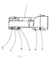
- La figure 3 est une vue en plan illustrant la face latérale d'un bloc différentiel présentant une configuration de détrompage comportant sept caractéristiques.
- FIGS. 1 and 2 are two partial perspective views, respectively illustrating two different keying configurations implemented for the association of a circuit breaker and a differential unit,
- Figure 3 is a plan view illustrating the side face of a differential unit having a keying configuration having seven characteristics.
Sur les figures 1 et 2, on voit deux boítiers modulaires A et B renfermant respectivement un
bloc différentiel 1 et un disjoncteur 2, lesdits boítiers étant destinés à être juxtaposés sur un
même rail non représenté et à être fixés l'un à l'autre par leur faces latérales 3,4 par
l'intermédiaire de moyens de fixation M.In Figures 1 and 2, we see two modular boxes A and B respectively containing a
Sur la figure 1, le boítier du bloc différentiel 1 comporte sur sa face latérale 3, destinée à
être accolée au disjoncteur 2, au voisinage de sa face arrière 5 de fixation au rail, cinq
pions de détrompage 6,7,8,9,10 . Parmi ces cinq pions, deux 7,9 ont été bouterollés ou
découpés tandis que les trois autres 6,8,10 s'étendent perpendiculairement à ladite face
latérale 3 d'un côté de l'évidement E destiné à permettre la fixation du bloc différentiel 1
sur le rail. De la même manière, le boítier du disjoncteur 2 comporte, en des emplacements
correspondant à ceux des pions 6 à 10 lorsque le bloc différentiel 1 est associé au
disjoncteur 2, des orifices 11 à 15. Les deux orifices 12,14 situés en regard des pions
bouterollés 7,9, comportent encore des obturateurs, tandis que les trois orifices 11,13,15
situés en regard des pions 6,8,10 n'en comportent plus, ceux-ci ayant été retirés, par
exemple par découpage, de manière à permettre l'introduction des trois pions 6,8,10. Dans
la réalisation représentée sur la figure 1, le premier pion 6 associé à son orifice 11 réalise le
détrompage de la norme industrielle. Le pion 10 réalise le détrompage par nombre de pôles
et permet de vérifier que les deux appareils sont de type tripolaire. Le pion 8 réalise le
détrompage par le calibre, c'est à dire ne permet l'association que lorsque le calibre des
appareils est inférieur à 63A pour le disjoncteur. In Figure 1, the housing of the
Sur la figure 2, le bloc différentiel comporte également cinq pions, mais ce sont les premier
6 troisième 8 et quatrième 9 pions qui subsistent, les autres ayant été escamotés, lesdits
pions 6,8,9 correspondant respectivement à la norme industrielle, à un calibre inférieur à
63A et au caractère tétrapolaire de l'appareil. On notera que l'on pourra ajouter à volonté
d'autres pions s'il est nécessaire de prendre en compte d'autres caractéristiques.In Figure 2, the differential block also has five pawns, but these are the first
6
Sur la figure 3, le bloc différentiel 1 comprend six emplacements pour un pion 16 à 21. Le
premier réalise un détrompage tenant à la norme industrielle, le 2ème au caractère
bipolaire, le 3ème à la norme domestique, le 4ème à un calibre de 63A, le 5ème au caractère
tétrapolaire et le 6ème au caractère tripolaire. L'appareil représenté est un bloc différentiel
tripolaire, de norme industrielle et de calibre 63A. C'est pourquoi les troisième 18, et
cinquième 20 pions en partant de la gauche ont été découpés ou bouterollés .In Figure 3, the
Ainsi, lors de leur fabrication, les boítiers des appareils sont équipés d'un certain nombre de pions de détrompage ou respectivement d'orifices munis d'obturateurs, venus de matière avec une pièce amovible du boítier. Cette pièce est unique pour tous les types d'appareils, ce qui permet de ne gérer qu'une seule pièce. Ce n'est qu'en fin de montage que les pions correspondant à des caractéristiques non vérifiées sont supprimés pour les appareils équipés de ces pions, en général les appareils additionnels, et que les obturateurs des orifices correspondant aux caractéristiques vérifiées sont retirés, pour les autres appareils, en général les appareils de base.Thus, during their manufacture, the housings of the devices are equipped with a number of coding pins or respectively of orifices provided with shutters, made of material with a removable part of the housing. This piece is unique for all types of devices, which allows you to manage only one room. It is only at the end of assembly that the pawns corresponding to non-verified characteristics are deleted for devices fitted of these pins, in general the additional devices, and that the shutters of the orifices corresponding to the verified characteristics are removed, for other devices, by general basic devices.
On notera que ce dispositif pourra être utilisé pour réaliser le détrompage entre d'autres appareils, par exemple entre un interrupteur différentiel et des disjoncteurs.It will be noted that this device can be used to provide keying between others devices, for example between a differential switch and circuit breakers.
On notera également que le détrompage ne se limitera pas à la norme, au calibre et au nombre de pôles mais pourra être élargi à d'autres critères.It will also be noted that the polarization will not be limited to the standard, the caliber and the number of poles but could be extended to other criteria.
L'invention permet de condamner toute mauvaise association tout en offrant une rationnalisation industrielle maximale. Ce principe de détrompage par pion et obturateur permet de détromper un grand nombre de combinaisons par ajout de pions supplémentaires.The invention makes it possible to condemn any bad association while offering a maximum industrial rationalization. This principle of coding by pawn and obturator allows you to undo a large number of combinations by adding additional pawns.
Claims (11)
Applications Claiming Priority (2)
| Application Number | Priority Date | Filing Date | Title |
|---|---|---|---|
| FR9716418 | 1997-12-18 | ||
| FR9716418A FR2773003B1 (en) | 1997-12-18 | 1997-12-18 | DECORING DEVICE FOR ELECTRICAL APPARATUS, PARTICULARLY FOR DIFFERENTIAL CIRCUIT BREAKERS AND CIRCUIT BREAKERS |
Publications (2)
| Publication Number | Publication Date |
|---|---|
| EP0926792A1 true EP0926792A1 (en) | 1999-06-30 |
| EP0926792B1 EP0926792B1 (en) | 2006-06-14 |
Family
ID=9515054
Family Applications (1)
| Application Number | Title | Priority Date | Filing Date |
|---|---|---|---|
| EP98410141A Expired - Lifetime EP0926792B1 (en) | 1997-12-18 | 1998-12-09 | Keying device for electrical apparatuses, in particular for circuit-breakers and differential switches |
Country Status (6)
| Country | Link |
|---|---|
| EP (1) | EP0926792B1 (en) |
| CN (1) | CN1085396C (en) |
| AT (1) | ATE330349T1 (en) |
| DE (1) | DE69834897T2 (en) |
| ES (1) | ES2264191T3 (en) |
| FR (1) | FR2773003B1 (en) |
Cited By (4)
| Publication number | Priority date | Publication date | Assignee | Title |
|---|---|---|---|---|
| FR2892852A1 (en) * | 2005-10-28 | 2007-05-04 | Hager Electro S A S Soc Par Ac | Keying system for prohibiting association of modular electrical apparatuses e.g. quadripolar circuit breaker, has rivets for grouping set of unipolar circuit breakers forming quadripolar circuit breaker |
| CN102082045A (en) * | 2009-11-30 | 2011-06-01 | 施耐德电器工业公司 | Electric accessory and switching device matched with the electric accessory |
| CN104733251A (en) * | 2012-12-31 | 2015-06-24 | 吴红平 | Intelligent molded case circuit breaker allowing communication protocol converter to be conveniently installed |
| CN104733250A (en) * | 2012-12-31 | 2015-06-24 | 吴红平 | Intelligent molded case circuit breaker convenient to install |
Citations (2)
| Publication number | Priority date | Publication date | Assignee | Title |
|---|---|---|---|---|
| EP0626712A1 (en) * | 1993-05-26 | 1994-11-30 | Bticino S.P.A. | A coupling device between two modular electric apparatus |
| EP0717425A1 (en) * | 1994-12-13 | 1996-06-19 | Bticino S.P.A. | A differential protection module with safety coupling for coupling to a multipole switch block |
-
1997
- 1997-12-18 FR FR9716418A patent/FR2773003B1/en not_active Expired - Fee Related
-
1998
- 1998-12-09 AT AT98410141T patent/ATE330349T1/en active
- 1998-12-09 EP EP98410141A patent/EP0926792B1/en not_active Expired - Lifetime
- 1998-12-09 DE DE69834897T patent/DE69834897T2/en not_active Expired - Lifetime
- 1998-12-09 ES ES98410141T patent/ES2264191T3/en not_active Expired - Lifetime
- 1998-12-18 CN CN98111661.2A patent/CN1085396C/en not_active Expired - Lifetime
Patent Citations (2)
| Publication number | Priority date | Publication date | Assignee | Title |
|---|---|---|---|---|
| EP0626712A1 (en) * | 1993-05-26 | 1994-11-30 | Bticino S.P.A. | A coupling device between two modular electric apparatus |
| EP0717425A1 (en) * | 1994-12-13 | 1996-06-19 | Bticino S.P.A. | A differential protection module with safety coupling for coupling to a multipole switch block |
Cited By (7)
| Publication number | Priority date | Publication date | Assignee | Title |
|---|---|---|---|---|
| FR2892852A1 (en) * | 2005-10-28 | 2007-05-04 | Hager Electro S A S Soc Par Ac | Keying system for prohibiting association of modular electrical apparatuses e.g. quadripolar circuit breaker, has rivets for grouping set of unipolar circuit breakers forming quadripolar circuit breaker |
| CN102082045A (en) * | 2009-11-30 | 2011-06-01 | 施耐德电器工业公司 | Electric accessory and switching device matched with the electric accessory |
| EP2328166A1 (en) * | 2009-11-30 | 2011-06-01 | Schneider Electric Industries SAS | Auxiliary switch intended for being connected to circuit breaker and comprising fool-proofing means, circuit breaker intended for engaging with such an auxiliary switch |
| FR2953325A1 (en) * | 2009-11-30 | 2011-06-03 | Schneider Electric Ind Sas | ELECTRICAL AUXILIARY BEING INTENDED TO BE CONNECTED TO A CUTTING DEVICE AND COMPRISING DETROMPING MEANS, CUTTING DEVICE FOR COLLABORATING WITH SUCH AN AUXILIARY |
| CN102082045B (en) * | 2009-11-30 | 2015-02-18 | 施耐德电器工业公司 | Electric accessory and switching device matched with the electric accessory |
| CN104733251A (en) * | 2012-12-31 | 2015-06-24 | 吴红平 | Intelligent molded case circuit breaker allowing communication protocol converter to be conveniently installed |
| CN104733250A (en) * | 2012-12-31 | 2015-06-24 | 吴红平 | Intelligent molded case circuit breaker convenient to install |
Also Published As
| Publication number | Publication date |
|---|---|
| ATE330349T1 (en) | 2006-07-15 |
| FR2773003B1 (en) | 2000-02-11 |
| CN1085396C (en) | 2002-05-22 |
| EP0926792B1 (en) | 2006-06-14 |
| CN1228603A (en) | 1999-09-15 |
| DE69834897D1 (en) | 2006-07-27 |
| FR2773003A1 (en) | 1999-06-25 |
| ES2264191T3 (en) | 2006-12-16 |
| DE69834897T2 (en) | 2006-11-30 |
Similar Documents
| Publication | Publication Date | Title |
|---|---|---|
| EP0598811B2 (en) | Hermaphrodite electrical connector | |
| EP0123590A1 (en) | Connector | |
| EP1376638B1 (en) | Electromagnetic protection and control assembly | |
| EP0715375A1 (en) | Modular electrical assembly | |
| EP0926792A1 (en) | Keying device for electrical apparatuses, in particular for circuit-breakers and differential switches | |
| EP0649158B1 (en) | Differential protection block with cable passage | |
| CA2348111A1 (en) | Multiple contact device for power bus bar systems | |
| EP2849295B1 (en) | Electric distribution assembly comprising a multipole electric power distribution comb. | |
| EP0004266A1 (en) | Support assembly for a bus bar set | |
| FR2787933A1 (en) | Protecting operators from accidental contact with electrical terminals by providing insulating screens which slide within one another such that only one terminal at a time is accessible to tools | |
| FR2789523A1 (en) | INTERCONNECTION BLOCK FOR ELECTRICAL APPLIANCES | |
| FR2645602A1 (en) | PNEUMATIC OR HYDRAULIC VALVE ASSEMBLY | |
| FR2749108A1 (en) | CONNECTOR FOR ESTABLISHING A TRANSVERSAL CONNECTION BETWEEN ALIGNED MODULAR ELECTRICAL APPLIANCES | |
| FR2845530A1 (en) | ELECTRICAL APPARATUS FOR MOUNTING ON A CHASSIS | |
| EP0478469A1 (en) | Terminals for the distribution of neutral and ground in an electrical distribution box | |
| FR2714540A1 (en) | Multiple socket for socket. | |
| EP1107363B1 (en) | Monopolar modular distribution frame | |
| FR2783668A1 (en) | CHASSIS, ESPECIALLY FOR ELECTRICAL EQUIPMENT | |
| FR2725071A1 (en) | DIFFERENTIAL SWITCH ASSOCIATED WITH ONE OR MORE CIRCUIT PROTECTION ELEMENTS SUCH AS FUSE OR CIRCUIT BREAKERS | |
| FR2699745A1 (en) | Power supply socket with integrated protection from live contacts | |
| EP0797271B1 (en) | Base for current socket | |
| EP2849288B1 (en) | Electric apparatus supplied by a comb and comprising at least one terminal | |
| FR2511199A1 (en) | Safety mains socket with protected terminals - has rocking cover plate with sliding action and only accepts simultaneous insertion of plug prongs | |
| WO2017064415A1 (en) | Circuit breaker panel | |
| EP0926775B1 (en) | Housing for electrical connectors |
Legal Events
| Date | Code | Title | Description |
|---|---|---|---|
| PUAI | Public reference made under article 153(3) epc to a published international application that has entered the european phase |
Free format text: ORIGINAL CODE: 0009012 |
|
| AK | Designated contracting states |
Kind code of ref document: A1 Designated state(s): AT DE ES GB IT |
|
| AX | Request for extension of the european patent |
Free format text: AL;LT;LV;MK;RO;SI |
|
| RAP1 | Party data changed (applicant data changed or rights of an application transferred) |
Owner name: SCHNEIDER ELECTRIC INDUSTRIES SA |
|
| 17P | Request for examination filed |
Effective date: 19991115 |
|
| AKX | Designation fees paid |
Free format text: AT DE ES GB IT |
|
| RAP1 | Party data changed (applicant data changed or rights of an application transferred) |
Owner name: SCHNEIDER ELECTRIC INDUSTRIES SA |
|
| RAP1 | Party data changed (applicant data changed or rights of an application transferred) |
Owner name: SCHNEIDER ELECTRIC INDUSTRIES SAS |
|
| GRAP | Despatch of communication of intention to grant a patent |
Free format text: ORIGINAL CODE: EPIDOSNIGR1 |
|
| GRAS | Grant fee paid |
Free format text: ORIGINAL CODE: EPIDOSNIGR3 |
|
| GRAA | (expected) grant |
Free format text: ORIGINAL CODE: 0009210 |
|
| AK | Designated contracting states |
Kind code of ref document: B1 Designated state(s): AT DE ES GB IT |
|
| REG | Reference to a national code |
Ref country code: GB Ref legal event code: FG4D Free format text: NOT ENGLISH |
|
| REF | Corresponds to: |
Ref document number: 69834897 Country of ref document: DE Date of ref document: 20060727 Kind code of ref document: P |
|
| GBT | Gb: translation of ep patent filed (gb section 77(6)(a)/1977) |
Effective date: 20060929 |
|
| REG | Reference to a national code |
Ref country code: ES Ref legal event code: FG2A Ref document number: 2264191 Country of ref document: ES Kind code of ref document: T3 |
|
| PLBE | No opposition filed within time limit |
Free format text: ORIGINAL CODE: 0009261 |
|
| STAA | Information on the status of an ep patent application or granted ep patent |
Free format text: STATUS: NO OPPOSITION FILED WITHIN TIME LIMIT |
|
| 26N | No opposition filed |
Effective date: 20070315 |
|
| PGFP | Annual fee paid to national office [announced via postgrant information from national office to epo] |
Ref country code: AT Payment date: 20131126 Year of fee payment: 16 Ref country code: DE Payment date: 20131206 Year of fee payment: 16 |
|
| REG | Reference to a national code |
Ref country code: DE Ref legal event code: R119 Ref document number: 69834897 Country of ref document: DE |
|
| REG | Reference to a national code |
Ref country code: AT Ref legal event code: MM01 Ref document number: 330349 Country of ref document: AT Kind code of ref document: T Effective date: 20141209 |
|
| PG25 | Lapsed in a contracting state [announced via postgrant information from national office to epo] |
Ref country code: DE Free format text: LAPSE BECAUSE OF NON-PAYMENT OF DUE FEES Effective date: 20150701 |
|
| PG25 | Lapsed in a contracting state [announced via postgrant information from national office to epo] |
Ref country code: AT Free format text: LAPSE BECAUSE OF NON-PAYMENT OF DUE FEES Effective date: 20141209 |
|
| PGFP | Annual fee paid to national office [announced via postgrant information from national office to epo] |
Ref country code: GB Payment date: 20161207 Year of fee payment: 19 |
|
| PGFP | Annual fee paid to national office [announced via postgrant information from national office to epo] |
Ref country code: IT Payment date: 20161221 Year of fee payment: 19 Ref country code: ES Payment date: 20161111 Year of fee payment: 19 |
|
| GBPC | Gb: european patent ceased through non-payment of renewal fee |
Effective date: 20171209 |
|
| PG25 | Lapsed in a contracting state [announced via postgrant information from national office to epo] |
Ref country code: IT Free format text: LAPSE BECAUSE OF NON-PAYMENT OF DUE FEES Effective date: 20171209 |
|
| PG25 | Lapsed in a contracting state [announced via postgrant information from national office to epo] |
Ref country code: GB Free format text: LAPSE BECAUSE OF NON-PAYMENT OF DUE FEES Effective date: 20171209 |
|
| REG | Reference to a national code |
Ref country code: ES Ref legal event code: FD2A Effective date: 20190702 |
|
| PG25 | Lapsed in a contracting state [announced via postgrant information from national office to epo] |
Ref country code: ES Free format text: LAPSE BECAUSE OF NON-PAYMENT OF DUE FEES Effective date: 20171210 |