EP0926758B1 - Nickel-metal hydride storage battery for back-up power source - Google Patents
Nickel-metal hydride storage battery for back-up power source Download PDFInfo
- Publication number
- EP0926758B1 EP0926758B1 EP98124421A EP98124421A EP0926758B1 EP 0926758 B1 EP0926758 B1 EP 0926758B1 EP 98124421 A EP98124421 A EP 98124421A EP 98124421 A EP98124421 A EP 98124421A EP 0926758 B1 EP0926758 B1 EP 0926758B1
- Authority
- EP
- European Patent Office
- Prior art keywords
- battery
- nickel
- batteries
- positive electrode
- power source
- Prior art date
- Legal status (The legal status is an assumption and is not a legal conclusion. Google has not performed a legal analysis and makes no representation as to the accuracy of the status listed.)
- Expired - Lifetime
Links
Images



Classifications
-
- H—ELECTRICITY
- H01—ELECTRIC ELEMENTS
- H01M—PROCESSES OR MEANS, e.g. BATTERIES, FOR THE DIRECT CONVERSION OF CHEMICAL ENERGY INTO ELECTRICAL ENERGY
- H01M10/00—Secondary cells; Manufacture thereof
- H01M10/42—Methods or arrangements for servicing or maintenance of secondary cells or secondary half-cells
- H01M10/44—Methods for charging or discharging
-
- H—ELECTRICITY
- H01—ELECTRIC ELEMENTS
- H01M—PROCESSES OR MEANS, e.g. BATTERIES, FOR THE DIRECT CONVERSION OF CHEMICAL ENERGY INTO ELECTRICAL ENERGY
- H01M10/00—Secondary cells; Manufacture thereof
- H01M10/24—Alkaline accumulators
- H01M10/26—Selection of materials as electrolytes
-
- H—ELECTRICITY
- H01—ELECTRIC ELEMENTS
- H01M—PROCESSES OR MEANS, e.g. BATTERIES, FOR THE DIRECT CONVERSION OF CHEMICAL ENERGY INTO ELECTRICAL ENERGY
- H01M10/00—Secondary cells; Manufacture thereof
- H01M10/34—Gastight accumulators
- H01M10/345—Gastight metal hydride accumulators
-
- H—ELECTRICITY
- H01—ELECTRIC ELEMENTS
- H01M—PROCESSES OR MEANS, e.g. BATTERIES, FOR THE DIRECT CONVERSION OF CHEMICAL ENERGY INTO ELECTRICAL ENERGY
- H01M4/00—Electrodes
- H01M4/02—Electrodes composed of, or comprising, active material
- H01M4/36—Selection of substances as active materials, active masses, active liquids
- H01M4/48—Selection of substances as active materials, active masses, active liquids of inorganic oxides or hydroxides
- H01M4/52—Selection of substances as active materials, active masses, active liquids of inorganic oxides or hydroxides of nickel, cobalt or iron
-
- H—ELECTRICITY
- H01—ELECTRIC ELEMENTS
- H01M—PROCESSES OR MEANS, e.g. BATTERIES, FOR THE DIRECT CONVERSION OF CHEMICAL ENERGY INTO ELECTRICAL ENERGY
- H01M10/00—Secondary cells; Manufacture thereof
- H01M10/42—Methods or arrangements for servicing or maintenance of secondary cells or secondary half-cells
- H01M2010/4292—Aspects relating to capacity ratio of electrodes/electrolyte or anode/cathode
-
- H—ELECTRICITY
- H01—ELECTRIC ELEMENTS
- H01M—PROCESSES OR MEANS, e.g. BATTERIES, FOR THE DIRECT CONVERSION OF CHEMICAL ENERGY INTO ELECTRICAL ENERGY
- H01M4/00—Electrodes
- H01M4/02—Electrodes composed of, or comprising, active material
- H01M4/36—Selection of substances as active materials, active masses, active liquids
- H01M4/38—Selection of substances as active materials, active masses, active liquids of elements or alloys
- H01M4/383—Hydrogen absorbing alloys
-
- Y—GENERAL TAGGING OF NEW TECHNOLOGICAL DEVELOPMENTS; GENERAL TAGGING OF CROSS-SECTIONAL TECHNOLOGIES SPANNING OVER SEVERAL SECTIONS OF THE IPC; TECHNICAL SUBJECTS COVERED BY FORMER USPC CROSS-REFERENCE ART COLLECTIONS [XRACs] AND DIGESTS
- Y02—TECHNOLOGIES OR APPLICATIONS FOR MITIGATION OR ADAPTATION AGAINST CLIMATE CHANGE
- Y02E—REDUCTION OF GREENHOUSE GAS [GHG] EMISSIONS, RELATED TO ENERGY GENERATION, TRANSMISSION OR DISTRIBUTION
- Y02E60/00—Enabling technologies; Technologies with a potential or indirect contribution to GHG emissions mitigation
- Y02E60/10—Energy storage using batteries
-
- Y—GENERAL TAGGING OF NEW TECHNOLOGICAL DEVELOPMENTS; GENERAL TAGGING OF CROSS-SECTIONAL TECHNOLOGIES SPANNING OVER SEVERAL SECTIONS OF THE IPC; TECHNICAL SUBJECTS COVERED BY FORMER USPC CROSS-REFERENCE ART COLLECTIONS [XRACs] AND DIGESTS
- Y02—TECHNOLOGIES OR APPLICATIONS FOR MITIGATION OR ADAPTATION AGAINST CLIMATE CHANGE
- Y02P—CLIMATE CHANGE MITIGATION TECHNOLOGIES IN THE PRODUCTION OR PROCESSING OF GOODS
- Y02P70/00—Climate change mitigation technologies in the production process for final industrial or consumer products
- Y02P70/50—Manufacturing or production processes characterised by the final manufactured product
Definitions
- the present invention relates to a nickel-metal hydride storage batteries to be applied to back-up power sources for maintaining, in place of main power sources, operating states or conditions of electric appliances such as a guidance light (taxing guidance light), an emergency light, an information telecommunication system and the like at an emergency such as unforeseen power failure.
- a guidance light taxing guidance light
- an emergency light an information telecommunication system and the like at an emergency such as unforeseen power failure.
- the nickel-metal hydride storage batteries which employ a hydrogen storage alloy capable of absorbing and desorbing hydrogen in a reversible manner as a negative electrode material have been popularized as the power sources for telecommunication apparatuses, computers, video recording apparatuses and the like, in place of nickel-cadmium batteries, since they can be sealed and have a higher energy density than the nickel-cadmium storage batteries.
- the nickel metal-hydride storage batteries have since been widely used as the main power sources for cordless appliances such as telecommunication apparatuses, computers and video recording appliances, they have not been used as the back-up power sources. This is because there was no suitable battery design and no charging method of the nickel metal-hydride storage batteries as the back-up power sources which must stand by in a state of constantly maintaining their discharge capacities sufficient for irregular discharging.
- trickle charge For the conventional back-up power sources using the nickel-cadmium storage batteries, so-called trickle charge has been employed, whereby the batteries are constantly supplied with a minute charging current. According to the trickle charge, the batteries are constantly maintained to the fully charged states.
- the discharge capacity of the battery decreases seriously, and it is impossible to maintain a satisfactory discharge capacity for a long-term.
- Such decrease in battery capacities is due to the proceedings of oxidation of the hydrogen storage alloy contained in the negative electrodes, facilitated by bringing the batteries into the overcharged state during the trickle charge. That is, the oxidation of the hydrogen storage alloy causes an increase in internal resistance of the batteries due to the decrease in hydrogen storaging ability of the alloy and consumption of the electrolyte.
- an intermittent charge has been proposed in, for instance, Japanese Unexamined Patent Publication No. Hei 9-117074 or Proceedings of the 1997 communications society conference of IEICE (Proceedings II, page 531).
- the intermittent charge is a method of maintain a battery in nearly full-charged state by charging the battery intermittently to compensate the self-discharge quantity of the battery during the last idle period or the last quiescence in the charging.
- the primary object of the present invention is to solve the above-mentioned problems and to provide a back-up power source which is capable of maintaining the discharge capacity of the nick-metal hydride storage battery for a long term and is suitable for the back-up power source of the guidance lights, the emergency lights, the information telecommunication systems and the like.
- the present invention provides a nickel metal-hydride storage battery for back-up power source to be subjected to an intermittent charge comprising: at least one positive electrode consisting mainly of nickel hydroxide; at least one negative electrode consisting mainly of a hydrogen storage alloy powder; at least one separator; and an alkaline electrolyte, characterized in that a theoretical electric capacity ratio of said positive electrode to said negative electrode is from 1:1.5 to 1:2.0, and an amount of said alkaline electrolyte is from 1.7 g to 3.5 g per 1 Ah of the theoretical electric capacity of said positive electrode, and said alkaline electrolyte contains potassium hydroxide and sodium hydroxide at a total molar concentration of from 7 to 10 mol/L, and the molar ratio of the potassium hydroxide to the sodium hydroxide is 1:1 to 1:4.
- the invention provides a nickel metal-hydride storage battery for back-up power source, which is characterized in that the charging in said intermittent charge is controlled under a system selected from the group consisting of the - ⁇ v control system, the dT/dt control system and the timer control system.
- the nickel metal-hydride storage battery for back-up power source is characterized in that said positive electrode contains, as an additive, at least one of an yttrium metal powder and an yttrium oxide powder.
- the nickel metal-hydride storage battery for back-up power source is characterized in that an amount of said additive is from 0.1 to 5 parts by weight for 100 parts by weight of said nickel hydroxide.
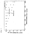
- FIG. 1 is a characteristic diagram showing relationships between charge/discharge cycles and the capacity maintenance rates of the batteries.
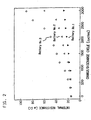
- FIG. 2 is a characteristic diagram showing relationships between charge/discharge cycles and internal resistances of the batteries.
- FIG. 3 is a characteristic diagram showing relationships between the continuous charging duration and the internal resistances of the batteries under an atmosphere of 65°C.
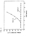
- FIG. 4 is a characteristic diagram showing relationships between the continuous charging duration and the internal resistances of the batteries under an atmosphere of 65°C.
- FIG. 5 is a characteristic diagram showing relationships between the molar concentration of the alkaline electrolytes and utilization rates of the positive electrode active materials.
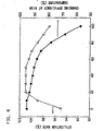
- FIG. 6 is a characteristic diagram showing relationships between the molar concentration of potassium hydroxide to that of sodium hydroxide, and the utilization rate of the positive electrode active material as well as the charging efficiency at high temperatures.
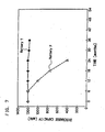
- FIG. 7 is a diagram showing a result of an accelerated cycle life test for a battery subjected to the intermittent charge in accordance with the present invention and of another battery subjected to the conventional trickle charge.
- FIG. 8 is a diagram showing a result of the accelerated cycle life test for batteries, which indicates a relationship between a time for testing and a discharge capacity of the batteries.
- a paste prepared by compounding mainly of a nickel hydroxide powder and a cobalt compound powder as a conductive agent was filled in a substrate consisting of foamed nickel.
- the substrate filled with the paste was pressed to have a predetermined thickness and cut into a size for a battery of AA size, thereby to produce a positive electrode plate.
- a paste consisting mainly of a hydrogen storage alloy powder was applied on both side faces of a perforated Ni-plated stainless steel sheet. After pressing the sheet to have a predetermined thickness, it was cut into the size for battery of AA size, thereby to produce a negative electrode plate.
- the laminated plates were wound up. together in a spiral fashion with a separator consisting of a nonwoven fabric of polypropylene interposed therebetween, thereby to produce an electrode group.
- the obtained electrode group was enclosed in a metal battery case.
- An alkaline electrolyte was prepared by dissolving lithium hydroxide in an aqueous solution of potassium hydroxide of a concentration of 7.5 mol/L, at 1 mol/L.
- the alkaline electrolyte is such that has conventionally been used in the nickel-metal hydride storage battery for the telecommunication apparatuses and computers.
- the obtained battery was stood still under an atmosphere at 25°C for 12 hours. Then the battery was subjected to an activation of charging at a current of 0.1 CmA for 15 hours and discharging at a current of 0.2 CmA for 4 hours.
- a cycle of charging the battery under the - ⁇ V control system at a charging current of 1/2 CmA until a fully charged state with an idle period of one day was repeated.
- a self-discharge quantity of the battery is about 5% of the discharge capacity thereof.
- the respective batteries were discharged until their terminal voltages were dropped to 1.0 V for every 100 cycles so as to derive the discharge capacities.
- Battery No. 1 demonstrates a high capacity maintenance rate for a long-term even when the charge/discharge cycles are repeated.
- the internal resistance of Battery No. 1 remains to be low for along term.
- the capacity maintenance rates of Batteries No. 2 and No. 3 decrease at an early stage of the cycles as compared with that of Battery No. 1, and the internal resistances increase. The deteriorations of these batteries proceed with the repetition of the charge/discharge cycle and become remarkable when the repetition is not less than 400 cycles in particular.
- the theoretical electric-capacity ratio of the positive electrode to the negative electrode is preferably 1:1.5 - 1:2.0. Further, it is preferable to set the amount of the alkaline electrolyte to 1.7 - 3.5 g per 1 Ah of the theoretical electric capacity of the positive electrode.
- Powders "D” through “F” were prepared as follows.
- the alloy powder having the same composition was subjected to a similar treatment by using an aqueous solution of potassium hydroxide of a concentration of 4 mol/L in place of the aqueous solution of lithium hydroxide.
- the obtained hydrogen storage alloy powder is named as Powder D.
- the alloy powder having the same composition was subjected to a similar treatment by using an aqueous solution of sodium hydroxide of a concentration of 4 mol/L.
- the obtained hydrogen storage alloy powder is named as Powder E.
- the alloy powder without being subjected to any treatment with an aqueous alkaline solution is named as Powder F.
- the magnetization rate of the alloy increases by immersing the alloy in an aqueous alkaline solution. It is considered that the increase in magnetization rate is due to an oxidation of misch metal or manganese in the alloy by the aqueous alkaline solution and a formation of single phase of nickel or cobalt which constitutes these alloy.
- the hydrogen storage alloy treated with the lithium hydroxide aqueous solution demonstrates a higher magnetization rate as compared with the hydrogen storage alloy treated with the aqueous solution of potassium hydroxide or that of sodium hydroxide.
- lithium hydroxide further promotes the oxidation reaction of the misch metal or manganese in the hydrogen storage alloy.
- lithium hydroxide By an addition of lithium hydroxide to the alkaline electrolyte, it becomes possible to stably derive an excellent discharge characteristic of the battery at the early stage. However, if lithium hydroxide exists in the alkaline electrolyte, the oxidation of the hydrogen storage alloy gradually proceeds, thereby to decrease the hydrogen storaging ability of the alloy and to further consume the alkaline electrolyte. As the back-up power source, not only to have an excellent early stage performance, the battery is also required to maintain the performance for a long term.
- Nickel-metal hydride storage batteries similar to those in Example 1 were assembled by using alkaline electrolytes of different species.
- a battery assembled by using an alkaline electrolyte prepared by dissolving lithium hydroxide in an aqueous solution of potassium hydroxide having a concentration of 7.5 mol/L at 1 mol/L which had conventionally been used in the nickel-metal hydride storage battery for the telecommunication apparatuses and computers is named as Battery "P" of the comparative example.
- Another battery was assembled in a similar manner by using an alkaline electrolyte prepared by dissolving lithium hydroxide in an aqueous solution of sodium hydroxide having a concentration of 7.5 mol/L at 1 mol/L. This battery is named as Battery "Q" of the comparative example.
- Still another battery was assembled by using an alkaline electrolyte containing only potassium hydroxide having a concentration of 8.5 mol/L. This battery is named as Battery “R”.
- Another battery was also assembled by using an alkaline electrolyte containing only sodium hydroxide having a concentration of 8.5 mol/L. This battery is named as Battery "S”.
- Batteries P, Q, R and S were then subjected to an accelerated reliability test designed for the nickel-metal hydride storage battery for back-up power source, whereby an increases in internal resistance of the batteries were examined during a continuous charging at a charging current of 0.2 CmA under an atmosphere at 65°C. The result thereof are shown by the diagrams in FIG. 3 and FIG. 4.
- Batteries R and S employing the alkaline electrolytes not including lithium hydroxide maintain their low internal resistances for a long term, and thus have a high reliability as the battery for back-up power source.
- the internal resistances of Batteries P and Q with the alkaline electrolytes containing lithium hydroxide increase with the progress of the charging. As previously described, this is due to the oxidation of the hydrogen storage alloy by the lithium hydroxide in the electrolyte and consumption of the alkaline electrolyte during the oxidation reaction.
- Batteries P and Q are found to be inferior in their long-term reliability. Although Battery R demonstrates a high utilization rate, high-temperature charging efficiency thereof is low. Battery S demonstrates an excellent long-term reliability and a high high-temperature charging efficiency, but the utilization rate thereof is not satisfactory. Therefore, any of Batteries P through S cannot satisfy the performance required as the back-up power source.
- Batteries were therefore configured by using the electrolyte containing potassium hydroxide and sodium hydroxide at different ratio and an investigation was conducted on their performances.
- the relationship between the concentration of potassium hydroxide or that of sodium hydroxide and the utilization rate of the positive electrode active material is shown by the diagram in FIG. 5.
- the utilization rate decreases at their concentrations of not more than 7 mol/L or not less than 10 mol/L.
- the concentration in the alkaline electrolyte containing potassium hydroxide or sodium hydroxide singly, it is therefore preferable to make the concentration to a range of 7 - 10 mol/L.
- the total concentration is preferably set to a range of 7 - 10 mol/L when the alkaline electrolyte containing potassium hydroxide and sodium hydroxide at a certain ratio.
- batteries were therefore configured by using the electrolyte containing potassium hydroxide and sodium hydroxide in a total amount of 8.5 mol/L.
- the relationship between the concentration ratio of potassium hydroxide to sodium hydroxide in the electrolyte and the utilization rate of the positive electrode active material is shown by the diagram in FIG. 6.
- the relationship between the concentration ratio and the charging efficiency at high temperature is also shown by the diagram in FIG. 6.
- the high-temperature charging efficiency is improved with the increase in the ratio of sodium hydroxide (i.e., decrease in the ratio of potassium hydroxide).
- the utilization rate of the positive electrode active material decreases abruptly when the ratio of potassium hydroxide reaches not less than 20%.
- any of the batteries with the alkaline electrolyte containing both of potassium hydroxide and sodium hydroxide however demonstrates a higher utilization rate as compared the batteries with the alkaline electrolyte containing one of these singly.
- concentration ratio of potassium hydroxide to 20% to 50%, to the sodium hydroxide in the electrolyte, it is possible to realize an excellent high-temperature charging efficiency and a high utilization rate at the same time.
- a similar tendency is recognized by varying the total amount of potassium hydroxide and sodium hydroxide in the alkaline electrolyte in a range of 7 - 10 mol/L.
- a nickel-metal hydride storage battery was configured by using the alkaline electrolyte containing potassium hydroxide and sodium hydroxide in 8.5 mol/L at the total amount and whose molar concentration ratio is 30% : 70% in a manner similar to Battery P.
- the battery is named as Battery "T”.
- Battery P employing the alkaline electrolyte prepared by dissolving lithium hydroxide in an aqueous solution of potassium hydroxide of a concentration of 7.5 mol/L, at 1 mol/L which has conventionally been used was subjected to trickle charge (Charging current: 1/20 CmA, Atmospheric temperature: 65 °C) which is also the conventional charging system. The results thereof are shown in the diagram in FIG. 7.
- a nickel-metal hydride storage battery for back-up power source, to use an alkaline electrolyte containing no lithium hydroxide which promotes the oxidation of the hydrogen storage alloy and to employ an intermittent charge system.
- a paste prepared by compounding mainly of nickel hydroxide powder and a cobalt compound as a conductive agent was filled in a substrate consisting of foamed nickel.
- the substrate filled with the paste was pressed to have a predetermined thickness and cut into a size for a battery of AA size, thereby to produce a positive electrode plate.
- a paste comprising 100 parts by weight of nickel hydroxide powder and 3 parts by weight of yttrium oxide (Y 2 O 3 ) was applied on both side faces of a perforated Ni-plated stainless steel sheet. After pressing the sheet to make it to have a predetermined thickness, it was cut into the size for the battery of AA size, thereby to produce a positive electrode plate.
- Y 2 O 3 yttrium oxide
- the positive electrode plate and the negative electrode plate obtained in the above-mentioned manner were laminated with a separator made of a nonwoven fabric of polypropylene interposed therebetween. Then, the laminated sheets were wound up together in a spiral fashion, thereby to produce an electrode group. The obtained electrode group was enclosed in a metal battery case.
- the batteries obtained in the above-mentioned manner were stood still at an atmospheric temperature of 25°C for 12 hours and then subjected to an initial charge/discharge (charging at a current of 0.1 CmA for 15 hours, and discharging at a current of 0.2 CmA for 4 hours) for their initial activation.
- Battery V employing the positive electrode added with yttrium oxide powder demonstrates a about 4% higher high-temperature charging efficiency than Battery U employing the positive electrode with no yttrium oxide powder.
- the batteries were discharged at a current of 0.2 CmA until their terminal voltages were dropped to 1.0 V/cell for every 6 months, to confirm the discharge capacities of the batteries. The results thereof are shown in the diagram in FIG. 8.
- the battery's characteristic of maintaining a discharge capacity at a high temperature is improved.
- yttrium oxide it is preferable to add 0.1 - 5 parts by weight of yttrium oxide to 100 parts by weight of nickel hydroxide contained in the positive electrode.
Landscapes
- Chemical & Material Sciences (AREA)
- Chemical Kinetics & Catalysis (AREA)
- Electrochemistry (AREA)
- General Chemical & Material Sciences (AREA)
- Engineering & Computer Science (AREA)
- Manufacturing & Machinery (AREA)
- Secondary Cells (AREA)
- Inorganic Chemistry (AREA)
- Battery Electrode And Active Subsutance (AREA)
Description
and said alkaline electrolyte contains potassium hydroxide and sodium hydroxide at a total molar concentration of from 7 to 10 mol/L, and the molar ratio of the potassium hydroxide to the sodium hydroxide is 1:1 to 1:4.
| Battery No. | Theoretical capacity ratio of positive electrode/negative electrode | Amount of Electrolyte (g/Ah) |
| 1 | 1.7 | 2.5 |
| 2 | 1.7 | 1.6 |
| 3 | 1.3 | 2.5 |
| Alloy Powder | Treatment with Aqueous solution | Concentration of Alkali | Magnetization of the Alloy (emu/g) | |
| | lithium hydroxide | 4 mol/L | 2.8 | |
| | potassium hydroxide | 4 mol/L | 1.1 | |
| | sodium hydroxide | 4 mol/L | 1.0 | |
| F | None | -- | 0.1 |
| Battery | Alkaline electrolyte | Utilization rate | High temperature charging efficiency |
| P | Aqueous solution of KOH of 7.5 mol/L added with LiOH at 1 mol/ | 100% | 75% |
| Q | Aqueous solution of NaOH of 7.5 mol/L added with LiOH at 1 mol/ | 98% | 95% |
| R | Aqueous solution of 8.5 mol/L potassium hydroxide | 97% | 60% |
| S | Aqueous solution of 8.5 mol/L sodium hydroxide | 95% | 95% |
| Battery | Positive electrode plate additives | Utilization rate of the positive electrode active material | High temperature charging efficiency |
| U | Cobalt hydroxide | 101% | 92% |
| V | Cobalt hydroxide and yttrium oxide | 101% | 96% |
Claims (4)
- A nickel metal-hydride storage battery for back-up power source to be subjected to an intermittent charge comprising: at least one positive electrode consisting mainly of nickel hydroxide; at least one negative electrode consisting mainly of a hydrogen storage alloy powder; at least one separator; and an alkaline electrolyte, characterized in that a theoretical electric capacity ratio of said positive electrode to said negative electrode is from 1:1.5 to 1:2.0, and an amount of said alkaline electrolyte is from 1.7 g to 3.5 g per 1 Ah of the theoretical electric capacity of said positive electrode,
and said alkaline electrolyte contains potassium hydroxide and sodium hydroxide at a total molar concentration of from 7 to 10 mol/L, and the molar ratio of the potassium hydroxide to the sodium hydroxide is 1:1 to 1:4. - The nickel metal-hydride storage battery for back-up power source in accordance with claim 1, characterized in that the charging in said intermittent charge is controlled under a system selected from the group consisting of the -ΔV control system, the dT/dt control system and the timer control system.
- The nickel metal-hydride storage battery for back-up power source in accordance with claim 1, characterized in that said positive electrode contains, as an additive, at least one of an yttrium metal powder and an yttrium oxide powder.
- The nickel metal-hydride storage battery for back-up power source in accordance with claim 3, characterized in that an amount of said additive is from 0.1 to 5 parts by weight for 100 parts by weight of said nickel hydroxide.
Applications Claiming Priority (8)
| Application Number | Priority Date | Filing Date | Title |
|---|---|---|---|
| JP35960897 | 1997-12-26 | ||
| JP35960897 | 1997-12-26 | ||
| JP727398 | 1998-01-19 | ||
| JP727398 | 1998-01-19 | ||
| JP5778798 | 1998-03-10 | ||
| JP5778798 | 1998-03-10 | ||
| JP10273369A JP2962326B1 (en) | 1997-12-26 | 1998-09-28 | Nickel-hydrogen storage battery for backup power supply |
| JP27336998 | 1998-09-28 |
Publications (2)
| Publication Number | Publication Date |
|---|---|
| EP0926758A1 EP0926758A1 (en) | 1999-06-30 |
| EP0926758B1 true EP0926758B1 (en) | 2003-10-22 |
Family
ID=27454689
Family Applications (1)
| Application Number | Title | Priority Date | Filing Date |
|---|---|---|---|
| EP98124421A Expired - Lifetime EP0926758B1 (en) | 1997-12-26 | 1998-12-22 | Nickel-metal hydride storage battery for back-up power source |
Country Status (4)
| Country | Link |
|---|---|
| EP (1) | EP0926758B1 (en) |
| JP (1) | JP2962326B1 (en) |
| CN (1) | CN1181589C (en) |
| DE (1) | DE69819123T2 (en) |
Families Citing this family (5)
| Publication number | Priority date | Publication date | Assignee | Title |
|---|---|---|---|---|
| CN101165960B (en) * | 2006-10-20 | 2011-08-17 | 兰州金川科力远电池有限公司 | Solar energy nickel-hydrogen charging battery manufacture process |
| CN101188309B (en) * | 2006-11-17 | 2010-12-01 | 湖南科力远新能源股份有限公司 | A making technology for nickel hydrogen high-temperature charging battery |
| JP5481803B2 (en) * | 2008-05-02 | 2014-04-23 | 株式会社Gsユアサ | Nickel metal hydride storage battery |
| JPWO2014050074A1 (en) * | 2012-09-25 | 2016-08-22 | 三洋電機株式会社 | Alkaline storage battery and storage battery system using the same. |
| WO2014068868A1 (en) * | 2012-10-30 | 2014-05-08 | 三洋電機株式会社 | Nickel metal hydride storage battery and storage battery system |
Family Cites Families (12)
| Publication number | Priority date | Publication date | Assignee | Title |
|---|---|---|---|---|
| JPS63193466A (en) * | 1987-02-04 | 1988-08-10 | Sanyo Electric Co Ltd | Metal-hydrogen alkali battery |
| DE3854727T2 (en) * | 1987-03-25 | 1996-05-30 | Matsushita Electric Ind Co Ltd | Gas-tight nickel hydride battery and method of manufacture. |
| JP2858862B2 (en) * | 1990-04-04 | 1999-02-17 | 三洋電機株式会社 | Metal-hydrogen alkaline storage battery |
| JP2989877B2 (en) * | 1990-10-22 | 1999-12-13 | 東芝電池株式会社 | Nickel hydride rechargeable battery |
| JPH05211069A (en) * | 1992-01-31 | 1993-08-20 | Matsushita Electric Ind Co Ltd | Square type sealed alkaline battery using hydrogen storage alloy negative electrode |
| JP3097347B2 (en) * | 1992-09-18 | 2000-10-10 | 松下電器産業株式会社 | Nickel-metal hydride battery |
| JP3365577B2 (en) * | 1994-05-27 | 2003-01-14 | 松下電器産業株式会社 | Single-cell and unit cells of sealed nickel-hydrogen storage batteries |
| KR100416428B1 (en) * | 1995-09-28 | 2004-05-27 | 가부시키가이샤 유아사코오포레이션 | A hydrogen occlusion electrode, a nickel electrode, and an alkaline storage battery |
| US5807643A (en) * | 1995-10-13 | 1998-09-15 | Kabushiki Kaisha Toshiba | Nickel-hydrogen secondary battery |
| JP3390309B2 (en) * | 1996-09-27 | 2003-03-24 | 松下電器産業株式会社 | Sealed alkaline storage battery |
| JPH10255833A (en) * | 1997-03-14 | 1998-09-25 | Hitachi Maxell Ltd | Manufacturing method of sealed hydride secondary battery |
| JP3489960B2 (en) * | 1997-04-01 | 2004-01-26 | 松下電器産業株式会社 | Alkaline storage battery |
-
1998
- 1998-09-28 JP JP10273369A patent/JP2962326B1/en not_active Expired - Lifetime
- 1998-12-22 EP EP98124421A patent/EP0926758B1/en not_active Expired - Lifetime
- 1998-12-22 DE DE69819123T patent/DE69819123T2/en not_active Expired - Lifetime
- 1998-12-25 CN CNB981260632A patent/CN1181589C/en not_active Expired - Lifetime
Also Published As
| Publication number | Publication date |
|---|---|
| EP0926758A1 (en) | 1999-06-30 |
| CN1181589C (en) | 2004-12-22 |
| DE69819123T2 (en) | 2004-07-08 |
| JP2962326B1 (en) | 1999-10-12 |
| JPH11329481A (en) | 1999-11-30 |
| DE69819123D1 (en) | 2003-11-27 |
| CN1221994A (en) | 1999-07-07 |
Similar Documents
| Publication | Publication Date | Title |
|---|---|---|
| EP0723305B1 (en) | Nickel positive electrode for use in alkaline storage battery. | |
| Shukla et al. | Nickel/iron batteries | |
| JPH01309265A (en) | Alkaline secondary battery and its manufacture | |
| JPH11204148A (en) | Discharge capacity recovery method of nonaqueous electrolyte secondary battery and circuit therefor | |
| Geng et al. | Characteristics of the High‐Rate Discharge Capability of a Nickel/Metal Hydride Battery Electrode | |
| US6097176A (en) | Method for managing back-up power source | |
| EP0926758A1 (en) | Nickel-metal hydride storage battery for back-up power source | |
| JP3390309B2 (en) | Sealed alkaline storage battery | |
| JP3358702B2 (en) | Nickel electrode for alkaline storage battery | |
| US6071644A (en) | Metal hydride storage cell and method of producing hydrogen absorbing alloy electrode | |
| US6207323B1 (en) | Hydrogen storage alloy electrode | |
| JP2000150000A (en) | How to manage backup power | |
| US20010033967A1 (en) | Alkaline storage battery that can be used with stability in a wide temperature range | |
| WO1998031063A1 (en) | Alkaline storage battery and method for charging battery | |
| JPH10134806A (en) | Hydrogen storage alloy electrode and nickel-hydrogen storage battery | |
| JP3314611B2 (en) | Nickel electrode for alkaline storage battery | |
| JP3802703B2 (en) | Nickel metal hydride battery | |
| JPH1021908A (en) | Active material for battery, and battery | |
| JP4326121B2 (en) | Alkaline storage battery | |
| JP3649655B2 (en) | Charging method for multiple parallel alkaline aqueous solution secondary batteries for backup | |
| JP2003257425A (en) | Nickel-metal hydride storage battery and method of manufacturing the same | |
| JP2001102085A (en) | Chemical conversion method of sealed nickel-hydrogen storage battery | |
| JPH04294058A (en) | Manufacturing method of metal oxide-hydrogen storage battery | |
| Fetcenko et al. | Advances in Ni-MH battery performance | |
| JP2861665B2 (en) | Maintenance and inspection method and capacity recovery method for nickel-cadmium batteries |
Legal Events
| Date | Code | Title | Description |
|---|---|---|---|
| PUAI | Public reference made under article 153(3) epc to a published international application that has entered the european phase |
Free format text: ORIGINAL CODE: 0009012 |
|
| 17P | Request for examination filed |
Effective date: 19981222 |
|
| AK | Designated contracting states |
Kind code of ref document: A1 Designated state(s): DE FR GB SE |
|
| AX | Request for extension of the european patent |
Free format text: AL;LT;LV;MK;RO;SI |
|
| AKX | Designation fees paid |
Free format text: DE FR GB SE |
|
| 17Q | First examination report despatched |
Effective date: 20000727 |
|
| GRAH | Despatch of communication of intention to grant a patent |
Free format text: ORIGINAL CODE: EPIDOS IGRA |
|
| GRAS | Grant fee paid |
Free format text: ORIGINAL CODE: EPIDOSNIGR3 |
|
| GRAA | (expected) grant |
Free format text: ORIGINAL CODE: 0009210 |
|
| AK | Designated contracting states |
Kind code of ref document: B1 Designated state(s): DE FR GB SE |
|
| REG | Reference to a national code |
Ref country code: GB Ref legal event code: FG4D |
|
| REG | Reference to a national code |
Ref country code: SE Ref legal event code: TRGR |
|
| REF | Corresponds to: |
Ref document number: 69819123 Country of ref document: DE Date of ref document: 20031127 Kind code of ref document: P |
|
| ET | Fr: translation filed | ||
| PLBE | No opposition filed within time limit |
Free format text: ORIGINAL CODE: 0009261 |
|
| STAA | Information on the status of an ep patent application or granted ep patent |
Free format text: STATUS: NO OPPOSITION FILED WITHIN TIME LIMIT |
|
| 26N | No opposition filed |
Effective date: 20040723 |
|
| REG | Reference to a national code |
Ref country code: FR Ref legal event code: PLFP Year of fee payment: 18 |
|
| REG | Reference to a national code |
Ref country code: FR Ref legal event code: PLFP Year of fee payment: 19 |
|
| REG | Reference to a national code |
Ref country code: FR Ref legal event code: PLFP Year of fee payment: 20 |
|
| PGFP | Annual fee paid to national office [announced via postgrant information from national office to epo] |
Ref country code: FR Payment date: 20171113 Year of fee payment: 20 |
|
| PGFP | Annual fee paid to national office [announced via postgrant information from national office to epo] |
Ref country code: SE Payment date: 20171213 Year of fee payment: 20 Ref country code: GB Payment date: 20171220 Year of fee payment: 20 |
|
| PGFP | Annual fee paid to national office [announced via postgrant information from national office to epo] |
Ref country code: DE Payment date: 20171220 Year of fee payment: 20 |
|
| REG | Reference to a national code |
Ref country code: DE Ref legal event code: R071 Ref document number: 69819123 Country of ref document: DE |
|
| REG | Reference to a national code |
Ref country code: GB Ref legal event code: PE20 Expiry date: 20181221 |
|
| REG | Reference to a national code |
Ref country code: SE Ref legal event code: EUG |
|
| PG25 | Lapsed in a contracting state [announced via postgrant information from national office to epo] |
Ref country code: GB Free format text: LAPSE BECAUSE OF EXPIRATION OF PROTECTION Effective date: 20181221 |