EP0926484A2 - Papier d'essai et tête de recueil d'analyte - Google Patents
Papier d'essai et tête de recueil d'analyte Download PDFInfo
- Publication number
- EP0926484A2 EP0926484A2 EP98310464A EP98310464A EP0926484A2 EP 0926484 A2 EP0926484 A2 EP 0926484A2 EP 98310464 A EP98310464 A EP 98310464A EP 98310464 A EP98310464 A EP 98310464A EP 0926484 A2 EP0926484 A2 EP 0926484A2
- Authority
- EP
- European Patent Office
- Prior art keywords
- test paper
- sample
- tip
- layer
- blood
- Prior art date
- Legal status (The legal status is an assumption and is not a legal conclusion. Google has not performed a legal analysis and makes no representation as to the accuracy of the status listed.)
- Withdrawn
Links
Images


Classifications
-
- G—PHYSICS
- G01—MEASURING; TESTING
- G01N—INVESTIGATING OR ANALYSING MATERIALS BY DETERMINING THEIR CHEMICAL OR PHYSICAL PROPERTIES
- G01N33/00—Investigating or analysing materials by specific methods not covered by groups G01N1/00 - G01N31/00
- G01N33/48—Biological material, e.g. blood, urine; Haemocytometers
- G01N33/50—Chemical analysis of biological material, e.g. blood, urine; Testing involving biospecific ligand binding methods; Immunological testing
- G01N33/52—Use of compounds or compositions for colorimetric, spectrophotometric or fluorometric investigation, e.g. use of reagent paper and including single- and multilayer analytical elements
- G01N33/525—Multi-layer analytical elements
-
- G—PHYSICS
- G01—MEASURING; TESTING
- G01N—INVESTIGATING OR ANALYSING MATERIALS BY DETERMINING THEIR CHEMICAL OR PHYSICAL PROPERTIES
- G01N33/00—Investigating or analysing materials by specific methods not covered by groups G01N1/00 - G01N31/00
- G01N33/48—Biological material, e.g. blood, urine; Haemocytometers
- G01N33/483—Physical analysis of biological material
- G01N33/487—Physical analysis of biological material of liquid biological material
- G01N33/49—Blood
- G01N33/491—Blood by separating the blood components
Definitions
- This invention relates to a test paper and an analyte measuring tip for measuring the amount of a target analyte in a given sample as, for example, in the measurement of blood sugar level in a blood sample.
- Blood sugar measuring devices which work by optically measuring the degree of coloration of a test paper (colorimetry) which assumes a color proportionately to the amount of glucose or other analyte in blood, are known.
- a conventional blood sugar measuring device of this construction the measurement of the color of the test paper has been carried out in a light measuring part provided with a light-emitting element and a light-receiving element by projecting light on the test paper and measuring the intensity of the light reflected from the test paper.
- This device subsequently to the work of supplying and spreading a blood sample on the test paper, requires the test paper to be inserted into a space where it can be shielded from ambient light before the measurement of the blood sugar level can be started. Besides suffering from this inconvenient mode of operation, this device has the problem that the interval between the time the blood is supplied and the time the measurement is started is not fixed, which gives rise to errors.
- the conventional test paper for prior art devices comprises a sheet substrate formed of a porous material capable of absorbing a sample, and a reagent deposited on the substrate.
- This test paper has pores in the sheet substrate with diameters of the order of 0.5 ⁇ m, and is at a disadvantage since it can be insufficiently permeable or attractive to water and can require an unduly long time for a sample to be fully measurable.
- the fact that the time for developing a sample is long as described above is unfavorable particularly for an automatic blood sugar measuring device.
- the object of this invention is to provide a test paper and an analyte measuring tip which permit reduction in the time required for developing a sample and allow measurements to be performed with high accuracy.
- test paper and the analyte measuring tip according to this invention will now be described below with reference to preferred embodiments which are illustrated in the accompanying drawings.
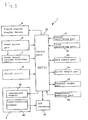
- an analyte measuring device 1 for a blood sample is provided with a casing 2 with a printed circuit 3 disposed therein. Further, the casing 2 is provided in one end portion thereof with a light measuring part 4. The casing 2 has a window with a liquid crystal display device (LCD) 9.
- LCD liquid crystal display device
- a microcomputer 10 as control means operating to control various functions of the analyte measuring device 1.
- This control means 10 has built therein an arithmetic part for computing a target analyte in blood (such as, for example, glucose) based on signals from the light measuring part 4.
- This arithmetic part as occasion demands, performs such correcting treatments as, for example, computation of hematocrit correction and computation of temperature correction.
- the light measuring part 4 is provided with a luminescent element (light-emitting diode) 41 and a light-receiving element (photodiode) 42. These elements are accommodated and retained in a holder 43.
- the luminescent element 41 is electrically connected to the control means 10 and the light-receiving element 42 is electrically connected to the control means 20 via an amplifier (not shown) and an analogue/digital converter 44.
- the luminescent element 41 is actuated by a signal from the control means 10 and caused to emit a pulse of light at prescribed intervals.
- the light pulse cycle is approximately in the range of 0.5 - 3.0 m.sec. and the duration of one pulse is approximately in the range of 0.05 - 0.3 m.sec.
- the wavelength of the light of this pulse is, for example, approximately in the range of 500 - 720 nm.
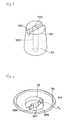
- an analyte measuring tip (hereinafter referred to simply as "tip") 5 having a test paper 53 therein is loaded in such a way as to be freely detachable.
- tip 5 an analyte measuring tip
- Preferred constructions of the tip 5 and of the test paper 53 will be described in detail later.
- the tip 5 is composed of a transparent or translucent tapering cylindrical cap 51. It may have colored transparency such as, for example, blue transparency.
- the test paper 53 set in place on the inner side of the bottom of the cap 51 (Fig. 1 refers).
- the test paper 53 is obtained by superposing a first layer 53a and opaque second layer 53b.
- a tube 52 projects from the outer side of the bottom of the cap 51.
- a sample such as blood is brought into contact with the leading end of this tube 52, the sample is aspirated into the tube 52 and transported to the test paper 53 by capillarity through a narrow conduit in the tube.
- the sample supplied to the approximately central part of the test paper 53 spreads in a radial pattern on the test paper 53 and is allowed to react with the reagent carried thereon and assume a color.
- the luminescent element 41 When the luminescent element 41 is lit while the tip 5 is loaded in the holder 43, the light emitted from the luminescent element impinges on the side of the test paper 53 which is the second layer 53b and produces reflected light.
- the intensity of the reflected light is equivalent to the intensity of coloration of the second layer 53b, namely to the amount of concentration of the target analyte in the sample.
- This reflected light is received by the light-receiving element 42 and subjected to photoelectric conversion therein.
- the light-receiving element 42 emits an analog signal corresponding to the amount of light received.
- the analog signal is amplified, when necessary, converted into a digital signal by the A/D converter 44, injected into the control means 10, and then stored in the first memory of a data memory 13.
- the analyte measuring device 1 is further provided with a power source portion 6, a power source voltage detector 7, a switch circuit 8, a control oscillating portion 11, a clock oscillator 12, the data memory 13, a buzzer output 14, an external output 15, and a temperature measurer 16.
- the power source portion 6 is loaded with a dry cell 61.
- the power source voltage detector 7 detects the voltage of the dry cell 61 and issues the result to the control means 10. Thus, the remaining power of the dry cell 61 can be checked.
- the switch circuit 8 detects the input to a switch and injects the signal corresponding to the input into the control means 10.
- a power source switch a power source switch, memory data read switch, clock setting/changing switch, resetting switch, buzzer ON/OFF selecting switch, and 50 Hz/60 Hz commercial power source frequency selecting switch may be cited.
- the power source switch can be turned ON/OFF by depressing an operating button 31.
- the other switches can be actuated by manipulating the operating button 31, and operating members 32, 33, 34, etc., either alone or in combination.
- the control oscillating portion 11 is a timer. It oscillates clock pulses at fixed intervals and supplies operating standard signals for a microcomputer (microprocessing unit: MPU) of the control means 10.
- MPU microprocessing unit
- the clock oscillating part 12 is a clock for specifying an absolute time (date and time). It oscillates clock pulses at fixed intervals and supplies an operating standard signal for the clock control circuit built in the control means 10.
- the data memory 13 is provided with a first memory (RAM), a second memory (ROM), and a third memory (nonvolatile RAM).
- RAM first memory
- ROM second memory
- nonvolatile RAM third memory
- the relation (calibration curve), tabulated in advance, between the absorbance computed from the magnitude of the result of the measurement of light and the amount of a target analyte in blood (hereinafter represented by "blood sugar level”) is stored.
- proofreading value peculiar to a relevant device is stored in advance.
- the term "proofreading value” as used herein embraces specific magnitudes of the amounts of reflected light and correction coefficients for the computation of final absorbance, for example.
- the blood sugar level is computed on the basis of such sets of data stored in the first second and third memories as described above.
- the blood sugar level is computed based on the ratio of the intensity of the reflected light from the test paper 53 after the development of color to the intensity of the reflected light prior to the development of color.
- the buzzer output 14 actuates a buzzer and causes emission of sound based on the signal from the control means 10.
- the external output 15 is intended to issue the data such as blood sugar level obtained by computation to a device such as, for example, a personal computer.
- the external output 15 has such a communication driver as, for example, RS232C, built therein.
- the external output 15 has an infrared ray-emitting element and a drive circuit therefor built therein.
- the temperature measurer 16 is provided with a temperature sensor such as a thermistor capable of measuring the ambient temperature.
- the temperature measurer 16 performs measurement of temperature from time to time.
- the temperature data so obtained is stored in the first memory of the data memory 13.
- the temperature data read from the first memory is injected into the control means 10 and utilized therein for correcting and computing the correct compensation for the blood sugar level in relation to temperature.
- test paper of this invention and of the analyte measuring tip furnished therewith will be described below.
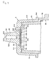
- the tip 5, as illustrated in Fig. 4, is composed of the cap 51, the tube 52 projecting from an end wall 511 of the cap 51, and the test paper 53 set in place inside the cap 51.
- the cap 51 is intended to support the test paper 53 and, at the same time, act to allow the cap 5 to be put in place on the light measuring part 4 of the analyte measuring device 1.
- a used cap can be removed from the measuring device by means of a release button 35 without hand-contact as illustrated in Fig. 1 and Fig. 9, the possibility of contamination by the blood is reduced. If the tip is kept covered with a cap 19 while it is being removed from or put onto the measuring device, contamination from the handler is very unlikely.
- the cap 51 is composed of the end wall 511, a barrel part 513, and a flange 514 formed on the outer periphery of the basal terminal of the barrel part 513. Further, inside the end wall 511, a pedestal 512 for fixing the test paper 53 is formed. The test paper 53 is fixed by its outer peripheral part 533 to the pedestal 512 by e.g., fusion or adhesion.
- the tip 5 is loaded in the light measuring part 4 of the analyte measuring device for blood by inserting holder 43 of the light measuring part 4 inside the barrel part 513 of the cap 51.
- the barrel part 513 is preferably tapered so that the inside diameter thereof converges gradually toward the end wall as illustrated in Fig. 4 and Fig. 9. By this taper, the tip can be infallibly inserted and loaded even when the inside diameter of the barrel differs slight from the outside diameter of the holder 43.
- the flange 514 functions as a grip part for allowing fingers to exert necessary force in attaching or detaching the tip 5 from the light measuring part 4 of the analyte measuring device 1.
- the tube 52 is intended to collect the sample of blood. It has a sample inlet conduit 520 running in a direction nearly perpendicular to the general plane of the test paper 53 and has a sample inlet 523 formed at the leading terminal thereof and a sample outlet 527 formed at the basal terminal thereof.
- the inner diameter or average diameter of the sample inlet conduit 520 is properly approximately in the range of 0.2 - 2.0 mm, preferably 0.3 - 1.0 mm. If the inner diameter of the sample inlet conduit 520 is unduly large, the transfer of the blood by capillarity will become difficult. If the inner diameter is unduly small, the blood will be supplied slowly and the time required for supplying the blood in an ample amount to the test paper 53 will be increased.
- the inside diameter (cross-sectional area) of the sample inlet conduit 520 may be constant or be varied along its longitudinal direction.
- the total length of the sample inlet conduit 520 is preferably in the approximate range of 1 - 10 mm, more preferably in the approximate range of 2 - 5 mm. If the sample inlet conduit 520 is unduly long, transfer of the blood by capillarity takes an unduly long time, If the conduit is unduly short, blood 18 (Fig. 13) may contact and possibly adhere to the outer side of the end wall of the cap 51.
- the leading terminal part and the basal terminal part of the tube 52 are respectively a sample inlet side terminal part 521 and a sample outlet side terminal part 525, as illustrated in Figs. 4 - 6.
- a groove 522 communicating with the sample inlet conduit 520 is formed on the terminal face of the sample inlet side terminal part 521.
- the groove 522 is a straight groove extending diametrically of the tube 52. The opposite ends of this groove 522 open in the outer peripheral surface of the tube 52.
- the groove 522 secures a flow path for blood and allows supply of the blood to the test paper 53 to be effected smoothly and infallibly because the sample inlet conduit 520 is not closed when the terminal face of the sample inlet side terminal part 521 is brought into contact with a surface, such as that of a finger, during the collection of blood.
- L 1 denotes the total peripheral length of the part forming the boundary between the groove 522 and the sample inlet conduit 520 and d 1 denotes the inside diameter of the sample inlet conduit 520 (the inner diameter near the sample inlet mouth 523)
- L 1 ⁇ ⁇ d 1 x 50% is preferred.
- the depth P1 of the groove 522 is not particularly critical but may be selected, depending on the condition of the skin. Generally, it is preferably not less than 0.1 mm and more preferably in the approximate range of 0.2 -1.8 mm. If the groove 522 is unduly shallow, the passage of blood in it will become insufficient, especially if a high pressure is exerted on the skin.
- the purpose of the groove 522 is that part of the terminal face of the sample inlet side terminal part 521 may not contact the skin when the terminal face is placed against the skin, and this may be achieved in different ways, for example by forming a plurality of grooves 522 radially (in the shape of a cross, for example) around the sample inlet mouth 523 of the sample inlet conduit 520 as the center or by forming them parallelly in such a manner as to touch the sample inlet conduit 520.
- the sample outflow side terminal part 525 (Fig. 6) of the tube 52 projects slightly toward the tip interior side (basal terminal side) from the end wall 511.
- a second groove 526 communicating with the sample inlet conduit 520 is formed on the terminal face of the sample inlet side terminal part 525.
- the groove 526 is a straight groove extending in the direction of the diameter of the tube 52.
- the opposite terminals of this groove 526 open in the outer peripheral surface of the projecting part 525 of the tube 52.
- the blood is spread quickly and uniformly over the test paper 53 and the measurement is obtained more accurately because the blood which has passed the sample inlet conduit 520 is released from the sample outlet mouth 527 and spread toward the outer periphery of the terminal part 525 via the groove 526 and then supplied to and developed on the test paper 53.
- L 2 denotes the total peripheral length of the part forming the boundary between the groove 526 and the sample inlet conduit 520 and d 2 denotes the inside diameter of the sample inlet conduit 520 (the inner diameter near the sample outlet mouth 527)
- L 2 ⁇ ⁇ d 2 x 50% is preferred.
- the blood which has flowed out of the sample outlet mouth 527 of the sample inlet conduit 520 can be diffused and developed more quickly and smoothly toward the outer periphery of the test paper.
- the depth P2 of the groove 526 though not particularly critical is preferred to be not less than 0.01 mm generally, and to be in the approximate range of 0.05 - 0.5 mm advantageously. If the depth P2 is unduly shallow, the groove 526 will possibly fail to fulfill its function properly.
- a plurality of grooves 526 may be formed radially (in the shape of a cross, for example) around the sample outlet mouth 527 of the sample inlet conduit 520 as the center or they may be formed parallelly in such a manner as to touch the sample inlet conduit 520.
- a gap 54 is formed in the tube 52 side of the test paper 53, namely between the test paper 53 and the inner side of the end wall 511 of the cap 51.
- This gap 54 functions to aid in the distribution of blood on the test paper 53.
- the blood which has flowed out of the sample outlet mouth 527 of the sample inlet conduit 520 expands radially through the gap 54 by capillarity, distribution of blood on the test paper 53 (particularly on the first layer 53a) can be attained quickly and uniformly.
- the depth of the gap 54 is preferred to be not less than 0.02 mm (average), particularly in the approximate range of 0.04 mm - 0.4 mm.
- a gap 54 having this depth can fulfill the function mentioned above very effectively.
- the depth of the gap 54 may be constant or may be varied (gradually decreased, for example) from the central part of the test paper 53 to the outer periphery thereof.
- a spacer 56 acts as separating means to ensure absence of contact between the test paper 53 and the holder 43 when the tip 5 is loaded in the light measuring part 4 of the analyte measuring device 1.
- This spacer 56 is formed of a plurality of convex parts, here, four circumferentially spaced at angular intervals of 90°, laid out along the peripheral direction on the inner side of the end wall 511. During the loading of the tip 5 in the light measuring part 4, it lodges against the leading end of the holder 43 of the light measuring part 4.
- the spacer 56 during the loading of the tip 5 in the light measuring part 4, also maintains fixed distances between the test paper 53 on the one part and the luminescent element 42 and the light-receiving element 42 of the light measuring part 4 on the other part.
- the spacer thus reduces errors of measurement due to variation in the distances mentioned above with consequent variation of the light values and contributes to accuracy of measurement.
- the cap 51 and the tube 52 constructed as described above are formed of a material having a desired rigidity.
- this rigid material various resinous materials including acryl type resin, polystyrene, polyethylene, polypropylene, hard polyvinyl chloride, polycarbonate, polymethyl methacrylate, ABS resin, polyesters, polyphenylene sulfide (PPS), polyamide, polyimide, and polyacetal and polymer alloys and polymer blends containing at least one of the compounds mentioned above may be cited.
- PPS polyphenylene sulfide
- polyamide polyimide
- polyacetal and polymer alloys and polymer blends containing at least one of the compounds mentioned above may be cited.
- such materials as acryl type resin which have high hydrophilicity and such materials which have undergone a treatment intended to impart hydrophilicity prove particularly advantageous because they are suitable for quick introduction and development of a sample.
- hydrophilicity can be attained by the addition or application of surfactant, water-soluble silicon, hydroxypropyl cellulose, polyethylene glycol or polypropylene glycol.
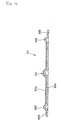
- test paper 53 The shape and construction of the test paper 53 will be described with reference to Fig. 9 to Fig. 12.
- test paper 53 is preferred to have such a circular overall shape as illustrated, it is not necessarily so.
- elliptic, square, rectangular, rhombic and other quadrilaterals, triangular, hexagonal, and octagonal shapes are possible.
- the outside diameter of the test paper 53 is preferably in the approximate range of 2 - 10 mm, more preferably in the approximate range of 3 - 6 mm.
- the thickness of the test paper 53 is preferably in the approximate range of 0.02 - 1.0 mm, more preferably in the approximate range of 0.05 - 0.4 mm.
- the test paper 53 is provided at the central part thereof, namely at the position fronting the sample inlet conduit 520, with a convex part 531 protruding toward the sample inlet conduit 520.
- the height of this convex part 531 is not particularly critical, at least the leading end of the convex part 531 is preferred to be insertable into the sample outlet mouth 527 of the conduit 520.
- the convex part 531 preferably has at least partly a diameter equal to or smaller than the inside diameter of the sample outlet mouth 527 of the sample inlet conduit 520 and also has a circular contour.
- the height of the convex part 531 is preferably in the approximate range of 0.02 - 1.0 mm, more preferably in the approximate range of 0.05 - 0.4 mm.
- the shape, size, etc. of the convex part 531 do not need to be limited to those specified above but may be properly selected to suit such factors as the cross section, shape, etc. of the sample inlet conduit 520.
- the convex part 531 provided in the manner described above enables the blood which has passed through the sample inlet conduit 520 to be supplied more quickly to the test paper 53.
- test paper 53 is further provided radially inside its outermost periphery with an annular convex part 532 protruding in the same direction as and centered on the convex part 531. Its leading end is opposite to and may be inserted in the sample reservoir 55 mentioned above.
- This annular convex part 532 has the function of regulating the development of blood on the test paper 53. It obstructs the outflow of excess blood radially beyond the periphery of the test paper 53b.
- the diameter of the annular convex part 532 is preferably in the approximate range of 70 - 95%, more preferably in the approximate range of 85 - 95%, of the outside diameter of the test paper 53 (which is the diameter of its second layer 53b).
- the width of the annular convex part 532 is preferably in the approximate range of 0.03 - 1.0 mm, more preferably in the approximate range of 0.05 - 0.5 mm.
- the height of the annular convex part 532 is preferably in the approximate range of 0.02 -1.0 mm, more preferably in the approximate range of 0.05 - 0.4 mm however.
- the shape, dimensions (diameter, width, height, etc) of the annular convex part 532 may be freely selected to suit the shape and other features of the cap 51.
- the convex part 531 and the annular convex part 532 which are constructed as described above may be formed, for example, by patterning in a die (projecting the basal terminal face of the test paper 53 by exertion of pressure as with a punch) or by mechanical cutting.
- test paper 53 constructed as described above is composed of the first layer 53a and the second layer 53b.
- the first layer 53a is what results from depositing a reagent such as a coloring reagent on a carrier capable of absorbing a sample.
- a carrier capable of absorbing a sample.
- this carrier is formed of a porous membrane or other sheetlike porous substrate.
- the reagent used for the impregnation is a reagent system which undergoes a reaction such as an oxidase reaction using the oxygen in the air as a substrate
- the use of a porous membrane as the carrier ensures sufficient supply of the oxygen from the air for the sample which has been developed on the first layer 53a and enables the reaction to proceed rapidly and therefore allows detection of the state of coloration without requiring removal of the sample or the filtrate thereof (red blood cells, etc.).
- porous membranes for the first layer 53a are a non-woven fabric, woven fabric, stretched sheet, membrane filter, or filter paper.
- polyesters, polyamides, polyolefins, polysulfones, celluloses, silicates, and fluorine type resins may be cited.
- the materials usable for the porous membrane include polyethylene terephthalate, polybutylene terephthalate, polyether sulfone, nitrocellulose, cellulose, glass, polytetrafluoroethylene (Teflon), nitrolized polyether sulfone.
- the material for forming the porous membrane preferably is a material inherently possessing hydrophilicity or a material which has undergone a treatment adapted for imparting hydrophilicity because the layer is produced by the impregnation with an aqueous solution having a reagent dissolved therein and also because the layer is expected to absorb and develop a sample quickly.
- the treatment for the impartation of hydrophilicity is the same as described above.
- glucose oxidase GOD
- peroxidase POD
- coloring agents such as, for example, 4-aminoantipyrine and N-ethyl-N-(2-hydroxy -3-sulfo-propyl)-m-toluidine
- reagents as, for example, ascorbic acid oxidase, alcohol oxidase, and cholesterol oxidase which react with the components of blood and the same coloring agents as mentioned above may be cited.
- the reagent may incorporate therein a buffer solution such as a phosphoric acid buffer solution.
- a buffer solution such as a phosphoric acid buffer solution.
- the kind and the composition of the reagent are not limited to those which are mentioned above provided they will provide a coloration signal at the observed face of the second layer 53b.
- the porous membrane of the first layer 53a of the kind mentioned above preferably contains pores of a diameter such that the blood cells, particularly the red blood cells, contained in a sample blood may be passed through the membrane.
- the diameter of the pores in the first layer 53a preferably is in the approximate range of 8 - 50 ⁇ m, more preferably in the approximate range of 10 - 30 ⁇ m. If the pore diameter is unduly small, the amount of red blood cells to be passed will decrease and the developability of blood will be degraded. If the pore diameter is unduly large, the deposition of the reagent will be attained only with difficulty and the sensitivity of coloration will be degraded because coloration will be attained only with difficulty.
- the first layer 53a described above has an outside dimension smaller than the outer dimension of the second layer 53b and it is positioned within the radially inner side of the annular convex part 532. Since the annular convex part 532 obstructs the outflow of the blood toward the outer peripheral side as described above, the first layer 53a which is responsible for the development of blood has need to be disposed radially within the annular convex part 532 but they could have equal outside diameters.
- the thickness of the first layer 53a is preferably in the approximate range of 10 - 1000 ⁇ m, more preferably in the approximate range of 50 - 200 ⁇ m.
- the second layer 53b is formed of the same porous membrane (sheetlike porous substrate) as mentioned above.
- porous membrane non-woven fabric, woven fabric, stretched sheet, membrane filter, and filter paper may be cited.
- the materials which are available for the formation of the porous membrane include polyesters, polyamides, polyolefins, polysulfones, and celluloses, for example, which are already mentioned above.
- the second layer 53b is preferably formed of an inherently hydrophilic material or a material which has undergone the treatment intended to impart hydrophilicity. The methods for the impartation of hydrophilicity are the same as those already cited above.
- the second layer 53b constructed as described above has the function to separate red blood cells as filtrate from the sample.
- the porous membrane which forms the second layer 53b preferably contains pores of a diameter such that at least the red blood cells contained in the blood sample are filtered out by the membrane. Therefore, the diameter of the pores in the second layer 53b is preferably not more than 5 ⁇ m, more preferably in the approximate range of 0.2 - 3.5 ⁇ m.
- the second layer may be either an isotropic membrane or an anisotropic membrane. If the pore diameter is unduly large, the red blood cells will pass the second layer 53b and transfer to the basal face (measuring face) side of the test paper 53 and will possibly degrade the accuracy of measurement of the color which developed.
- the first layer 53a and the second layer 53b may be joined throughout or partly in their entire surfaces or may be simply superposed without using any binding force.
- the thickness of the second layer 53b is preferably in the approximate range of 10 - 1000 ⁇ m, more preferably in the approximate range of 50 - 200 ⁇ m. It should be opaque enough that the presence of filtrate such as red cells on its rear face will not affect readings from its test face.
- a fixing part 533 is formed on the outer peripheral part of the test paper 53.
- a plurality of fixing points 534 are formed intermittently (preferably as spaced at intervals of an equal distance) along the outer peripheral part of the test paper 53 as illustrated in Fig. 11. As a result, ambient air is allowed to pass through the intervals between the adjacent fixing points 534.
- the air entrapped in the gap 54 and the sample reservoir 55 is efficiently discharged and the spread of blood can be carried out more quickly.
- the test paper 53 may be secured to the sample outlet side terminal part 525 by fusion or adhesion with adhesive agent. As a result, it is more stably supported and fixed on the cap 51 and possible deformations (bend, warp, wave, etc.) of the test paper 53 can be prevented; these could give rise to gaps, and obstruct the development of blood.
- Fig. 13 is a side view illustrating the way in which the tip 5 is used for collecting blood. As illustrated therein, the collection of blood is begun by puncturing the finger tip (or the earlobe) with a needle or a surgical knife and forcing blood 18 to flow out through the puncture in a small amount (for example, in the approximate range of 2 - 6 ⁇ l) onto the skin.
- the tip 5 is loaded in the light measuring part 4 of the analyte measuring device 1 and the terminal face of the sample inlet side terminal part 521 of the tube 52 is brought into contact with the skin.
- the blood 18 on the finger tip flows through the groove 522 and reaches the sample inlet mouth 523 and, on being aspirated by capillarity, flows inside the sample inlet conduit 520 in the direction of the basal terminal and reaches the sample outlet mouth 527.
- there is no possibility of the blood 18 on the finger tip being excessively dispersed on the skin and wasted, since it is effectively aspirated through the lateral side opening part of the groove 522 (the part opened in the outer peripheral face of the tube 52).
- the blood which has reached the sample outlet mouth 527 is brought into contact with and absorbed by the convex part 531 of the test paper 53 and part of the blood is allowed to pass through the groove 526 and reach the gap 54.
- the blood which has flowed into the gap 54 is absorbed and developed by the adjoining first layer 53a of the test paper 53 and meanwhile expanded radially in the direction of the outer periphery.
- absorbing power continues to be effective in the sample inlet conduit 520 to cause a continuous supply of the blood to the first layer 53a.
- the blood can be supplied to the first layer 53a (test paper 53) without any waste.
- the amount of the blood 18 on the finger tip is large and is supplied excessively to the first layer 53a, the possibility of the blood leading out of the test paper 53 and adhering to and smearing the inner face of the barrel part 52, the light measuring part 4, or their peripheral parts is precluded because the excess blood is retained in the sample reservoir 55 and prevented by the annular convex part 532 from flowing out toward the external periphery.
- the excess blood therefore, is handled more safely because it exerts no adverse effect on the next round of measurement and has no possibility of causing infection during the disposal of the used tip 5.
- the target analyte glucose, for example
- the test paper 53 assumes a color proportionately to the amount of the analyte.
- the blood components (excluding red blood cells) which have been colored migrate to the second layer 53b and color the second layer 53b in the same color tone with the same intensity.
- the red blood cells in the blood are passed through the first layer 53a but are not passed through the second layer 53b, they stagnate in the vicinity of the boundary between the first layer 53a and the second layer 53b.
- the target analyte (blood sugar level) in the blood is found by measuring the intensity of coloration of the second layer 53b with the analyte measuring device 1 in the manner described above.
- the red blood cells which are contained in the blood exert no adverse effect on the measurement of color by the test paper because they are filtered out by the second layer 53b, retained in the vicinity of the boundary between the first layer 53a and the second layer 53b, and prevented from migrating toward the basal terminal face of the second layer 53b.
- the accuracy of measurement can be high.
- the harmful effect of red blood cells and the like is eliminated to ensure accuracy of measurement. Because the first layer 53a passes red blood cells and meanwhile develops coloration; this development proceeds quickly and uniformly. Also because the blood components (excluding red blood cells and any other filtrate) which have been colored within the first layer 53a migrate to the second layer 53b and color that second layer, with the result that the intensity of the resultant coloration can be used for measurement. For these reasons, the time required for the measurement can be shortened.
- the blood 18 which has flowed out onto the finger tip can be supplied and developed on the test paper 53 quickly and infallibly by a simple procedure without reference to its amount. As a result, the measurement error is extremely small.
- a blood sugar level measuring test paper was manufactured in the shape and construction (two-layer laminate) illustrated in Fig. 10 - Fig. 12.
- the conditions of the component parts of the test paper were as follows.
- a blood sugar level measuring test paper formed of one layer of porous membrane was manufactured. The conditions of the component parts of the test paper were as shown below.
- Diameter of convex part 531 Same as in the working example described above.
- Width of annular convex part 532 Same as in the working example described above.
- This test paper was set in place in the tip having the same conditions as in the working example described above.
- a test paper was produced by following the procedure of Working Example 1 while using
- a test paper was produced by following the procedure of Working Example 1 while using
- test paper of this invention does not need to be limited to what is loaded on the tip 5 as described above.
- the test paper may be manufactured arbitrarily in various forms such as, for example, what is formed solely of itself, what is superposed on a basis (substrate) shaped like a plate or sheet, or what is retained (particularly nipped) by a holder.
- the working example used blood as the sample.
- This invention does not need to limit the sample to blood.
- the sample may be urine, lymph, cerebrospinal fluid, saliva, or other similar bodily humor, or a diluted solution thereof, or a concentrated solution thereof.
- the analyte aimed at by the measurement does not need to be limited to grape sugar (blood sugar level).
- grape sugar blood sugar level
- it may be protein, cholesterol, uric acid, creatine, alcohol, sodium or other inorganic ion, or hemoglobin (occult blood).
- the analyte measuring device fitted with the test paper or the analyte measuring tip according to this invention does not need to be limited to what operates by optically measuring the intensity of color of the test paper which has assumed the color in consequence of the reaction of the analyte in a sample with the reagent, computing the magnitude of measurement based on the result of the optical measurement, and displaying the outcome of the computation. It may be adapted to operate by electrically measuring a potential change which arises proportionately to the amount of the analyte in the sample, computing the magnitude of measurement based on the outcome of the electrical measurement, and displaying the magnitude.
- the test paper and the analyte measuring tip according to this invention can heighten the speed of development of the sample on the test paper and curtail the time required for the development. They also shortens the time which precedes the stabilization of the state of coloration. As a result, the measurement can be expedited.
- the measurement of color can be attained with high accuracy by eliminating the otherwise possible effect of red blood cells and the like.
- the analyte measuring tip according to this invention allows convenient, quick, and infallible collection of a sample and effects necessary development of the sample on the test paper without reference to the conditions of the sample such as, for example, constitution and amount of the sample, site of collection, and technique of collection. As a result, it is capable of affording an accurate magnitude of measurement.
- the analyte measuring tip allows easy handling and simplifies the operation of attachment thereof to the analyte measuring device. Particularly, it can be easily and infallibly loaded in a proper state. The possibility of involving error of measurement due to improper state of attachment, therefore, can be precluded.
- the contamination due to adhesion of the sample can be prevented and the used analyte measuring tip can be discarded with high safety.
- the analyte measuring device contributes advantageously to the automation of the measurement.
Landscapes
- Health & Medical Sciences (AREA)
- Life Sciences & Earth Sciences (AREA)
- Engineering & Computer Science (AREA)
- Hematology (AREA)
- Biomedical Technology (AREA)
- Immunology (AREA)
- Chemical & Material Sciences (AREA)
- Urology & Nephrology (AREA)
- Physics & Mathematics (AREA)
- Molecular Biology (AREA)
- General Physics & Mathematics (AREA)
- General Health & Medical Sciences (AREA)
- Food Science & Technology (AREA)
- Medicinal Chemistry (AREA)
- Pathology (AREA)
- Analytical Chemistry (AREA)
- Biochemistry (AREA)
- Cell Biology (AREA)
- Biotechnology (AREA)
- Microbiology (AREA)
- Ecology (AREA)
- Biophysics (AREA)
- Investigating Or Analysing Biological Materials (AREA)
- Investigating Or Analysing Materials By The Use Of Chemical Reactions (AREA)
- Investigating Or Analyzing Non-Biological Materials By The Use Of Chemical Means (AREA)
Applications Claiming Priority (2)
| Application Number | Priority Date | Filing Date | Title |
|---|---|---|---|
| JP36633797A JPH11183474A (ja) | 1997-12-24 | 1997-12-24 | 試験紙および成分測定用チップ |
| JP36633797 | 1997-12-24 |
Publications (2)
| Publication Number | Publication Date |
|---|---|
| EP0926484A2 true EP0926484A2 (fr) | 1999-06-30 |
| EP0926484A3 EP0926484A3 (fr) | 1999-10-20 |
Family
ID=18486536
Family Applications (1)
| Application Number | Title | Priority Date | Filing Date |
|---|---|---|---|
| EP98310464A Withdrawn EP0926484A3 (fr) | 1997-12-24 | 1998-12-18 | Papier d'essai et tête de recueil d'analyte |
Country Status (5)
| Country | Link |
|---|---|
| EP (1) | EP0926484A3 (fr) |
| JP (1) | JPH11183474A (fr) |
| CN (1) | CN1225450A (fr) |
| SG (1) | SG81255A1 (fr) |
| TW (1) | TW515887B (fr) |
Cited By (13)
| Publication number | Priority date | Publication date | Assignee | Title |
|---|---|---|---|---|
| WO2002062210A1 (fr) * | 2001-02-06 | 2002-08-15 | Roche Diagnostics Gmbh | Systeme permettant de controler la concentration d'analytes dans des fluides corporels |
| WO2003095969A2 (fr) * | 2002-05-08 | 2003-11-20 | Yorktest Laboratories Limited | Dispositif de prelevement d'echantillons |
| EP1365239A1 (fr) * | 2002-03-28 | 2003-11-26 | Fuji Photo Film Co., Ltd. | Dispositif de test de sang |
| GB2411230A (en) * | 2004-02-23 | 2005-08-24 | Johnson & Johnson Medical Ltd | Diagnostic test caps |
| US7282179B2 (en) * | 2002-03-28 | 2007-10-16 | Fujifilm Corporation | Blood testing unit and blood testing method and apparatus |
| US7300629B2 (en) | 2002-03-28 | 2007-11-27 | Fujifilm Corporation | Humoral testing unit |
| US7410613B2 (en) | 2002-03-28 | 2008-08-12 | Fujifilm Corporation | Humoral testing apparatus |
| EP2238444A2 (fr) * | 2008-01-09 | 2010-10-13 | Orono Spectral Solutions, Inc. | Appareil et procédé pour déterminer une teneur en analyte dans un fluide |
| EP2263544A1 (fr) * | 2009-05-18 | 2010-12-22 | F. Hoffmann-La Roche AG | Unité de test pour l'examen d'un liquide corporel et procédé de fabrication |
| US8034301B2 (en) | 2003-03-27 | 2011-10-11 | Terumo Kabushiki Kaisha | Test paper and porous membrane |
| US8613214B2 (en) | 2008-01-09 | 2013-12-24 | Orono Spectral Solutions, Inc. | Apparatus and method for determining analyte content in a fluid |
| WO2019227124A1 (fr) * | 2018-05-30 | 2019-12-05 | University Of South Australia | Dispositifs et procédés de collecte et de stockage d'échantillons de fluide pour analyse |
| CN115466671A (zh) * | 2022-09-28 | 2022-12-13 | 广纳达康(广州)生物科技有限公司 | 一种防冲液核酸扩增物检测装置及检测方法 |
Families Citing this family (11)
| Publication number | Priority date | Publication date | Assignee | Title |
|---|---|---|---|---|
| US6844149B2 (en) * | 2001-06-29 | 2005-01-18 | International Business Machines Corporation | Method, system, and apparatus for measurement and recording of blood chemistry and other physiological measurements |
| EP1424040A1 (fr) * | 2002-11-26 | 2004-06-02 | Roche Diagnostics GmbH | Dispositif de test pour fluides corporels |
| JP2004347436A (ja) * | 2003-05-21 | 2004-12-09 | Terumo Corp | 成分測定装置 |
| JP2005091315A (ja) * | 2003-09-19 | 2005-04-07 | Terumo Corp | 成分測定装置 |
| ATE548646T1 (de) | 2003-05-21 | 2012-03-15 | Terumo Corp | Vorrichtung zur messung einer komponente |
| JP4222896B2 (ja) * | 2003-07-25 | 2009-02-12 | テルモ株式会社 | 成分測定装置 |
| JP4493535B2 (ja) * | 2005-03-29 | 2010-06-30 | テルモ株式会社 | 試験紙 |
| JP5363124B2 (ja) * | 2009-01-15 | 2013-12-11 | テルモ株式会社 | 収納容器および試験具包装体 |
| WO2016134531A1 (fr) | 2015-02-28 | 2016-09-01 | 曾嵘斌 | Bandette réactive à produit chimique sec dotée de multiples couches de membranes à base de gradient de concentration |
| CN106198950A (zh) * | 2016-07-08 | 2016-12-07 | 艾康生物技术(杭州)有限公司 | 用于存放检测试纸的试纸盒和样本检测装置 |
| CN107064484A (zh) * | 2017-05-25 | 2017-08-18 | 杭州博旭生物技术有限公司 | 自吸式干式生化检测装置 |
Citations (6)
| Publication number | Priority date | Publication date | Assignee | Title |
|---|---|---|---|---|
| US4042335A (en) * | 1975-07-23 | 1977-08-16 | Eastman Kodak Company | Integral element for analysis of liquids |
| US4646753A (en) * | 1985-06-11 | 1987-03-03 | Becton, Dickinson And Company | Blood collector for microcollection container |
| US5100620A (en) * | 1989-05-15 | 1992-03-31 | Miles, Inc. | Capillary tube/gap reagent format |
| WO1994018559A1 (fr) * | 1993-02-11 | 1994-08-18 | Radiometer Medical A/S | Membrane detectrice asymetrique |
| US5366902A (en) * | 1990-10-30 | 1994-11-22 | Hypoguard (Uk) Limited | Collection and display device |
| JPH1019888A (ja) * | 1996-07-02 | 1998-01-23 | Terumo Corp | 血液検査具及び血液検査測定器 |
Family Cites Families (4)
| Publication number | Priority date | Publication date | Assignee | Title |
|---|---|---|---|---|
| US4627445A (en) * | 1985-04-08 | 1986-12-09 | Garid, Inc. | Glucose medical monitoring system |
| US4935346A (en) * | 1986-08-13 | 1990-06-19 | Lifescan, Inc. | Minimum procedure system for the determination of analytes |
| NL8800796A (nl) * | 1988-03-29 | 1989-10-16 | X Flow Bv | Werkwijze voor de chemische analyse van bestanddelen van een lichaamsvloeistof, alsmede een testinrichting en testpakket voor een dergelijke analyse. |
| GR1001410B (el) * | 1991-08-02 | 1993-11-30 | Ortho Pharma Corp | Επινόημα & μέ?οδος διεξαγωγής βιολογικών δοκιμασιών περιέχοντας σύστημα μοριακής διαλογής. |
-
1997
- 1997-12-24 JP JP36633797A patent/JPH11183474A/ja active Pending
-
1998
- 1998-12-18 EP EP98310464A patent/EP0926484A3/fr not_active Withdrawn
- 1998-12-19 TW TW87121253A patent/TW515887B/zh not_active IP Right Cessation
- 1998-12-21 SG SG9805874A patent/SG81255A1/en unknown
- 1998-12-24 CN CN 98111737 patent/CN1225450A/zh active Pending
Patent Citations (6)
| Publication number | Priority date | Publication date | Assignee | Title |
|---|---|---|---|---|
| US4042335A (en) * | 1975-07-23 | 1977-08-16 | Eastman Kodak Company | Integral element for analysis of liquids |
| US4646753A (en) * | 1985-06-11 | 1987-03-03 | Becton, Dickinson And Company | Blood collector for microcollection container |
| US5100620A (en) * | 1989-05-15 | 1992-03-31 | Miles, Inc. | Capillary tube/gap reagent format |
| US5366902A (en) * | 1990-10-30 | 1994-11-22 | Hypoguard (Uk) Limited | Collection and display device |
| WO1994018559A1 (fr) * | 1993-02-11 | 1994-08-18 | Radiometer Medical A/S | Membrane detectrice asymetrique |
| JPH1019888A (ja) * | 1996-07-02 | 1998-01-23 | Terumo Corp | 血液検査具及び血液検査測定器 |
Non-Patent Citations (1)
| Title |
|---|
| PATENT ABSTRACTS OF JAPAN vol. 098, no. 005, 30 April 1998 (1998-04-30) & JP 10 019888 A (TERUMO CORP), 23 January 1998 (1998-01-23) * |
Cited By (20)
| Publication number | Priority date | Publication date | Assignee | Title |
|---|---|---|---|---|
| US7276027B2 (en) | 2001-02-06 | 2007-10-02 | Roche Diagnostics Operations, Inc. | System, for monitoring the concentration of analytes in body fluids |
| WO2002062210A1 (fr) * | 2001-02-06 | 2002-08-15 | Roche Diagnostics Gmbh | Systeme permettant de controler la concentration d'analytes dans des fluides corporels |
| EP1365239A1 (fr) * | 2002-03-28 | 2003-11-26 | Fuji Photo Film Co., Ltd. | Dispositif de test de sang |
| US7282179B2 (en) * | 2002-03-28 | 2007-10-16 | Fujifilm Corporation | Blood testing unit and blood testing method and apparatus |
| US7300629B2 (en) | 2002-03-28 | 2007-11-27 | Fujifilm Corporation | Humoral testing unit |
| US7410613B2 (en) | 2002-03-28 | 2008-08-12 | Fujifilm Corporation | Humoral testing apparatus |
| WO2003095969A2 (fr) * | 2002-05-08 | 2003-11-20 | Yorktest Laboratories Limited | Dispositif de prelevement d'echantillons |
| WO2003095969A3 (fr) * | 2002-05-08 | 2004-01-08 | Yorktest Lab Ltd | Dispositif de prelevement d'echantillons |
| US8034301B2 (en) | 2003-03-27 | 2011-10-11 | Terumo Kabushiki Kaisha | Test paper and porous membrane |
| US8187457B2 (en) | 2003-03-27 | 2012-05-29 | Terumo Kabushiki Kaisha | Test paper and porous membrane |
| GB2411230A (en) * | 2004-02-23 | 2005-08-24 | Johnson & Johnson Medical Ltd | Diagnostic test caps |
| US8613214B2 (en) | 2008-01-09 | 2013-12-24 | Orono Spectral Solutions, Inc. | Apparatus and method for determining analyte content in a fluid |
| EP2238444A4 (fr) * | 2008-01-09 | 2011-12-21 | Orono Spectral Solutions Inc | Appareil et procédé pour déterminer une teneur en analyte dans un fluide |
| US8393198B2 (en) | 2008-01-09 | 2013-03-12 | OronoSpectral Solutions, Inc. | Apparatus and method for determining analyte content in a fluid |
| EP2238444A2 (fr) * | 2008-01-09 | 2010-10-13 | Orono Spectral Solutions, Inc. | Appareil et procédé pour déterminer une teneur en analyte dans un fluide |
| EP2263544A1 (fr) * | 2009-05-18 | 2010-12-22 | F. Hoffmann-La Roche AG | Unité de test pour l'examen d'un liquide corporel et procédé de fabrication |
| WO2019227124A1 (fr) * | 2018-05-30 | 2019-12-05 | University Of South Australia | Dispositifs et procédés de collecte et de stockage d'échantillons de fluide pour analyse |
| EP3803321A4 (fr) * | 2018-05-30 | 2022-01-19 | University Of South Australia | Dispositifs et procédés de collecte et de stockage d'échantillons de fluide pour analyse |
| CN115466671A (zh) * | 2022-09-28 | 2022-12-13 | 广纳达康(广州)生物科技有限公司 | 一种防冲液核酸扩增物检测装置及检测方法 |
| CN115466671B (zh) * | 2022-09-28 | 2023-12-15 | 广纳达康(广州)生物科技有限公司 | 一种防冲液核酸扩增物检测装置及检测方法 |
Also Published As
| Publication number | Publication date |
|---|---|
| JPH11183474A (ja) | 1999-07-09 |
| CN1225450A (zh) | 1999-08-11 |
| TW515887B (en) | 2003-01-01 |
| SG81255A1 (en) | 2001-06-19 |
| EP0926484A3 (fr) | 1999-10-20 |
Similar Documents
| Publication | Publication Date | Title |
|---|---|---|
| EP0926484A2 (fr) | Papier d'essai et tête de recueil d'analyte | |
| JP3618210B2 (ja) | 成分測定装置 | |
| KR100555194B1 (ko) | 분석장치 제조공정 | |
| EP1025442B1 (fr) | Dispositif d'analyse pourvu d'un support capillaire pour reactifs | |
| US5110724A (en) | Multi-analyte assay device | |
| US5681529A (en) | Biological fluid analyzing device | |
| CA1340389C (fr) | Dispositif d'analyse a volume defini | |
| US7575915B2 (en) | Biosensor | |
| JP4980324B2 (ja) | 成分測定装置 | |
| US7820451B2 (en) | Analytical test element | |
| US6338720B1 (en) | Collection device for collecting liquid sample | |
| EP0864363B1 (fr) | Dispositif pour le prélèvement d'échantillons liquides | |
| JPH04188065A (ja) | 液体試料分析用具および分析方法 | |
| EP1607042A1 (fr) | Accessoire d'echantillonnage de l'humeur et procede d'echantillonnage de l'humeur | |
| WO1992015863A1 (fr) | Bande de test amelioree | |
| US9089293B2 (en) | Test element for analyzing a body fluid | |
| JP2004347436A (ja) | 成分測定装置 | |
| JP3949126B2 (ja) | 成分測定用チップ | |
| KR100350694B1 (ko) | 시험지및성분측정용팁 | |
| EP1626269A1 (fr) | Dispositif de mesure de composant | |
| JP4222896B2 (ja) | 成分測定装置 | |
| JP2005091315A (ja) | 成分測定装置 | |
| JP4109100B2 (ja) | 体液採取具 | |
| JP2008082898A (ja) | 成分測定装置 |
Legal Events
| Date | Code | Title | Description |
|---|---|---|---|
| PUAI | Public reference made under article 153(3) epc to a published international application that has entered the european phase |
Free format text: ORIGINAL CODE: 0009012 |
|
| AK | Designated contracting states |
Kind code of ref document: A2 Designated state(s): AT BE CH CY DE DK ES FI FR GB GR IE IT LI LU MC NL PT SE |
|
| AX | Request for extension of the european patent |
Free format text: AL;LT;LV;MK;RO;SI |
|
| PUAL | Search report despatched |
Free format text: ORIGINAL CODE: 0009013 |
|
| AK | Designated contracting states |
Kind code of ref document: A3 Designated state(s): AT BE CH CY DE DK ES FI FR GB GR IE IT LI LU MC NL PT SE |
|
| AX | Request for extension of the european patent |
Free format text: AL;LT;LV;MK;RO;SI |
|
| RIC1 | Information provided on ipc code assigned before grant |
Free format text: 6G 01N 21/86 A, 6G 01N 33/52 B, 6G 01N 33/487 B |
|
| 17P | Request for examination filed |
Effective date: 19991001 |
|
| AKX | Designation fees paid |
Free format text: AT BE CH CY DE DK ES FI FR GB GR IE IT LI LU MC NL PT SE |
|
| 17Q | First examination report despatched |
Effective date: 20040825 |
|
| STAA | Information on the status of an ep patent application or granted ep patent |
Free format text: STATUS: THE APPLICATION IS DEEMED TO BE WITHDRAWN |
|
| 18D | Application deemed to be withdrawn |
Effective date: 20041226 |