EP0926319B1 - Dispositif pour séparer les gaz de carter d'un moteur à combustion interne et liaison pour ces gaz - Google Patents
Dispositif pour séparer les gaz de carter d'un moteur à combustion interne et liaison pour ces gaz Download PDFInfo
- Publication number
- EP0926319B1 EP0926319B1 EP19980122363 EP98122363A EP0926319B1 EP 0926319 B1 EP0926319 B1 EP 0926319B1 EP 19980122363 EP19980122363 EP 19980122363 EP 98122363 A EP98122363 A EP 98122363A EP 0926319 B1 EP0926319 B1 EP 0926319B1
- Authority
- EP
- European Patent Office
- Prior art keywords
- crankcase
- vapours
- separator
- engine
- oil
- Prior art date
- Legal status (The legal status is an assumption and is not a legal conclusion. Google has not performed a legal analysis and makes no representation as to the accuracy of the status listed.)
- Expired - Lifetime
Links
Images
Classifications
-
- F—MECHANICAL ENGINEERING; LIGHTING; HEATING; WEAPONS; BLASTING
- F02—COMBUSTION ENGINES; HOT-GAS OR COMBUSTION-PRODUCT ENGINE PLANTS
- F02F—CYLINDERS, PISTONS OR CASINGS, FOR COMBUSTION ENGINES; ARRANGEMENTS OF SEALINGS IN COMBUSTION ENGINES
- F02F7/00—Casings, e.g. crankcases or frames
-
- F—MECHANICAL ENGINEERING; LIGHTING; HEATING; WEAPONS; BLASTING
- F01—MACHINES OR ENGINES IN GENERAL; ENGINE PLANTS IN GENERAL; STEAM ENGINES
- F01M—LUBRICATING OF MACHINES OR ENGINES IN GENERAL; LUBRICATING INTERNAL COMBUSTION ENGINES; CRANKCASE VENTILATING
- F01M13/00—Crankcase ventilating or breathing
- F01M13/04—Crankcase ventilating or breathing having means for purifying air before leaving crankcase, e.g. removing oil
Definitions
- the present invention refers to a device to separate oil vapours from the crankcase of an internal combustion engine (blow by) provided with manifolds for connection to the blow-by circuit of said vapours and of a manifold to let fresh oil in the crankcase sump.
- the separator device for the blow-by oil vapours that come from the sump and from the crank chamber, is typically made as a separate part which is added to the engine when this one is being assembled.
- the European patent application EP 0 291 358 shows a separator device for the blow-by oil vapours from an internal combustion engine crankcase, consisting of a base and a cover in which the base is made by means of fusion integral to the crankcase of the engine in correspondance with one of its side walls.
- the separator device is closed by a lid plate whit an opening connected to the intake manifold through a pipe line.
- This separator do not need a support base as the conventional one, but the lid cannot be used neither to enlarge the separator nor to let fresh oil in the crankcase sump.
- Said object is achived by means of a separator for blow-by vapours presenting the characteristics indicated in claim 1.
- One of the advantages of the present invention consists in that it presents two access manifolds to the separator from the crank chamber, said access manifolds being spaced and located on a plane parallel to the axis of the crankcase. This makes it possible to keep one manifold constantly free, even in the case the inclination of the engine is very high, so that no oil can be sucked into the crank chamber.
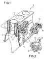
- the reference number 2 indicates the crankcase of an internal combustion engine made by means of ground fusion.
- the crankcase presents in-line cylinders and one crank chamber 5 on the side wall of the cylinders.
- at least two passages 6 and 7 for the oil vapours are built by fusion in correspondence with the second and third bay of the crankcase. Said passages, which are positioned in order not to interfere with the connecting rods, and which lay, spaced, on a plane parallel to the longitudinal axis of the crankcase, make the crank chamber communicate with the external wall of the crankcase through the holes 9 and 10.
- the holes 9 and 10 open inside a body forming the lower section, or base, 11, of a compartment for the separation 12 of oil vapours, said compartment being basically shaped as an equilateral triangle, in correspondence with the ends of one of its sides which is basically parallel to the plane defined by the upper face of the crankcase.
- This separator built by fusion together with the crankcase, presents inside walls forming a labyrinth and one vertex pointing towards the lower part of the crankcase.
- the upper section or cover 13 of the separator compartment which is made separately, again presents in its internal part the labyrinth pattern of the crankcase 11, and presents two manifolds 15 and 16, being the first one 15 adapted to carry vapours to the blow-by system and the second one 16 used as an inlet for fresh oil.
- a passage 18, is made centrally, in correspondence with the vertex pointing downwards, in the separator 12 and in the wall of the crankcase, and a manifold 19 built by fusion and connected to it, allow to introduce oil in the engine sump.
- the base and the cover of the separator are jointed by conventional means, i.e. screws, and a seal (not shown) can be put between them if necessary.
- the two manifolds spaced and parallel to the axis of the crankcase, allow the suction of blow-by vapours to be always free, independently from the working position of the engine.
Landscapes
- Engineering & Computer Science (AREA)
- Mechanical Engineering (AREA)
- General Engineering & Computer Science (AREA)
- Chemical & Material Sciences (AREA)
- Combustion & Propulsion (AREA)
- Lubrication Details And Ventilation Of Internal Combustion Engines (AREA)
Claims (4)
- Séparateur de vapeurs d'huile provenant d'un carter de moteur à combustion interne (fuite des gaz) consistant en une embase (11) et un capotage, dans lequel l'embase est fabriquée par fusion en une seule pièce avec le carter (2) du moteur, de manière correspondante à l'une des parois latérales de celui-ci, et est raccordée à la chambre de vilebrequin du moteur par l'intermédiaire d'au moins un collecteur (6, 7) fabriqué par fusion dans la paroi latérale du carter, et dans lequel le capotage (13) possède une tubulure (15) pour transférer les vapeurs de fuite des gaz vers le corps de papillon du système d'alimentation du moteur, caractérisé en ce que le capotage (13) possède une autre tubulure (16) qui permet à l'huile fraíche de pénétrer dans le moteur.
- Séparateur selon la revendication 1, caractérisé en ce que le capotage (13) et l'embase sont munis de parois internes qui sont au même niveau, et forment ainsi un labyrinthe.
- Séparateur selon la revendication 1, caractérisé en ce que ladite autre tubulure est raccordée au carter d'huile du moteur, par l'intermédiaire d'un passage (18) ménagé dans le séparateur de manière correspondante au sommet pointant vers le bas, et par l'intermédiaire d'un collecteur (19) fabriqué, par fusion, en une seule pièce avec la paroi du carter (2).
- Séparateur selon les revendications précédentes, caractérisé en ce que des encoches (21) permettant le passage de l'huile de décantation sont prévues dans les parois qui forment le labyrinthe.
Applications Claiming Priority (2)
| Application Number | Priority Date | Filing Date | Title |
|---|---|---|---|
| ITTO971133 IT1305593B1 (it) | 1997-12-23 | 1997-12-23 | Dispositivo separatore di vapori di olio dal basamento di un motore acombustione interna e collegamento per il ricircolo di tali vapori |
| ITTO971133 | 1997-12-23 |
Publications (2)
| Publication Number | Publication Date |
|---|---|
| EP0926319A1 EP0926319A1 (fr) | 1999-06-30 |
| EP0926319B1 true EP0926319B1 (fr) | 2002-10-23 |
Family
ID=11416229
Family Applications (1)
| Application Number | Title | Priority Date | Filing Date |
|---|---|---|---|
| EP19980122363 Expired - Lifetime EP0926319B1 (fr) | 1997-12-23 | 1998-11-25 | Dispositif pour séparer les gaz de carter d'un moteur à combustion interne et liaison pour ces gaz |
Country Status (4)
| Country | Link |
|---|---|
| EP (1) | EP0926319B1 (fr) |
| DE (1) | DE69808877T2 (fr) |
| ES (1) | ES2182206T3 (fr) |
| IT (1) | IT1305593B1 (fr) |
Cited By (1)
| Publication number | Priority date | Publication date | Assignee | Title |
|---|---|---|---|---|
| DE112008001694B4 (de) * | 2007-07-17 | 2018-05-09 | Avl List Gmbh | Brennkraftmaschine mit einem Kurbelgehäuse für mehrere Zylinder |
Families Citing this family (9)
| Publication number | Priority date | Publication date | Assignee | Title |
|---|---|---|---|---|
| JP3911950B2 (ja) * | 2000-02-25 | 2007-05-09 | スズキ株式会社 | 自動二輪車 |
| GB0212588D0 (en) | 2002-05-30 | 2002-07-10 | Ricardo Consulting Eng | Reciprocating piston internal combustion engines |
| JP4249504B2 (ja) * | 2003-02-17 | 2009-04-02 | マツダ株式会社 | オイルセパレータ構造及びオイルセパレータユニット |
| JP2004340096A (ja) | 2003-05-19 | 2004-12-02 | Fuji Heavy Ind Ltd | クランクケースのブリーザ装置 |
| GB2428600A (en) * | 2005-08-04 | 2007-02-07 | Ec Power As | A separating device |
| JP2009150350A (ja) * | 2007-12-21 | 2009-07-09 | Toyota Motor Corp | オイル分離装置 |
| DE102010004910A1 (de) * | 2010-01-19 | 2011-07-21 | GM Global Technology Operations LLC, ( n. d. Ges. d. Staates Delaware ), Mich. | Ölabscheidevorrichtung |
| FR2985769A1 (fr) * | 2012-01-12 | 2013-07-19 | Peugeot Citroen Automobiles Sa | Bloc-moteur d'un moteur a combustion interne |
| DE102013008117A1 (de) * | 2013-05-11 | 2014-11-13 | GM Global Technology Operations LLC (n. d. Ges. d. Staates Delaware) | Motorteil für einen Verbrennungsmotor und Verbrennungsmotor |
Family Cites Families (7)
| Publication number | Priority date | Publication date | Assignee | Title |
|---|---|---|---|---|
| FR1124307A (fr) * | 1954-06-03 | 1956-10-09 | Moteur à combustion interne | |
| DE3713210A1 (de) * | 1987-04-18 | 1988-11-03 | Porsche Ag | Entlueftungsvorrichtung mit integriertem oelabscheider |
| CA1328588C (fr) * | 1987-05-15 | 1994-04-19 | Honda Giken Kogyo Kabushiki Kaisha (Also Trading As Honda Motor Co., Ltd .) | Moteur a combustion interne |
| JP2690968B2 (ja) * | 1988-09-30 | 1997-12-17 | ヤマハ発動機株式会社 | V形エンジンの冷却装置 |
| US5474035A (en) * | 1994-07-08 | 1995-12-12 | Outboard Marine Corporation | Engine breather construction |
| DE19608066C1 (de) * | 1996-03-02 | 1997-06-05 | Daimler Benz Ag | Kurbelraumentlüftung für eine Brennkraftmaschine |
| TW376426B (en) * | 1996-10-16 | 1999-12-11 | Honda Motor Co Ltd | Engine for vehicle |
-
1997
- 1997-12-23 IT ITTO971133 patent/IT1305593B1/it active
-
1998
- 1998-11-25 DE DE1998608877 patent/DE69808877T2/de not_active Expired - Lifetime
- 1998-11-25 ES ES98122363T patent/ES2182206T3/es not_active Expired - Lifetime
- 1998-11-25 EP EP19980122363 patent/EP0926319B1/fr not_active Expired - Lifetime
Cited By (1)
| Publication number | Priority date | Publication date | Assignee | Title |
|---|---|---|---|---|
| DE112008001694B4 (de) * | 2007-07-17 | 2018-05-09 | Avl List Gmbh | Brennkraftmaschine mit einem Kurbelgehäuse für mehrere Zylinder |
Also Published As
| Publication number | Publication date |
|---|---|
| ES2182206T3 (es) | 2003-03-01 |
| DE69808877D1 (de) | 2002-11-28 |
| EP0926319A1 (fr) | 1999-06-30 |
| IT1305593B1 (it) | 2001-05-09 |
| ITTO971133A1 (it) | 1999-06-23 |
| DE69808877T2 (de) | 2003-08-07 |
Similar Documents
| Publication | Publication Date | Title |
|---|---|---|
| US4656991A (en) | Breather device for internal combustion engine | |
| US4528969A (en) | Blow-by gas returning device for V-type internal combustion engine | |
| US4501234A (en) | Blow-by gas passage system for internal combustion engines | |
| JPS5996469A (ja) | 内燃機関のブロ−バイガス取出装置 | |
| US4947812A (en) | Positive crankcase ventilation system | |
| EP0926319B1 (fr) | Dispositif pour séparer les gaz de carter d'un moteur à combustion interne et liaison pour ces gaz | |
| US20030230291A1 (en) | Engine blow-by gas distribution system | |
| EP0154910B1 (fr) | Dispositif renifleur pour moteur à combustion interne | |
| EP1498588A3 (fr) | Moteur à combustion interne à deux temps | |
| US4541399A (en) | Breather arrangement for internal combustion engine | |
| JP3389801B2 (ja) | エンジンのブローバイガス還元構造 | |
| EP3273019A1 (fr) | Dispositif de séparation gaz-liquide pour gaz de fuite dans un moteur et moteur | |
| JP3537554B2 (ja) | 船外機のブローバイガス還元装置 | |
| US4306522A (en) | Transfer port duct for two-stroke engines | |
| JPS6325162B2 (fr) | ||
| HK1060611A1 (en) | Four-cycle internal combustion engine | |
| US7124730B2 (en) | Oil catching system for an internal-combustion engine, particularly for an opposed-cylinder engine | |
| EP1805401A1 (fr) | Systeme de suralimentation interne pour moteurs | |
| EP1182343A3 (fr) | Agencement couvre-culasse pour un moteur à combustion interne | |
| JP3832531B2 (ja) | エンジンのブロ−バイガス通路 | |
| JPS6215451Y2 (fr) | ||
| US7047732B2 (en) | Outboard engine exhaust structure | |
| EP1321638A1 (fr) | Système de degasage pou le carter d'un moteur à combustion interne | |
| JPH0653709U (ja) | 縦乃至傾斜型の頭上弁式多気筒エンジンのブリーザ装置 | |
| CA2246848A1 (fr) | Moteur a quatre temps pour moteur hors bord |
Legal Events
| Date | Code | Title | Description |
|---|---|---|---|
| PUAI | Public reference made under article 153(3) epc to a published international application that has entered the european phase |
Free format text: ORIGINAL CODE: 0009012 |
|
| AK | Designated contracting states |
Kind code of ref document: A1 Designated state(s): DE ES FR GB SE |
|
| AX | Request for extension of the european patent |
Free format text: AL;LT;LV;MK;RO;SI |
|
| 17P | Request for examination filed |
Effective date: 19991008 |
|
| AKX | Designation fees paid |
Free format text: DE ES FR GB SE |
|
| 17Q | First examination report despatched |
Effective date: 20010626 |
|
| GRAG | Despatch of communication of intention to grant |
Free format text: ORIGINAL CODE: EPIDOS AGRA |
|
| GRAG | Despatch of communication of intention to grant |
Free format text: ORIGINAL CODE: EPIDOS AGRA |
|
| GRAH | Despatch of communication of intention to grant a patent |
Free format text: ORIGINAL CODE: EPIDOS IGRA |
|
| GRAH | Despatch of communication of intention to grant a patent |
Free format text: ORIGINAL CODE: EPIDOS IGRA |
|
| GRAA | (expected) grant |
Free format text: ORIGINAL CODE: 0009210 |
|
| AK | Designated contracting states |
Kind code of ref document: B1 Designated state(s): DE ES FR GB SE |
|
| REG | Reference to a national code |
Ref country code: GB Ref legal event code: FG4D |
|
| REF | Corresponds to: |
Ref document number: 69808877 Country of ref document: DE Date of ref document: 20021128 |
|
| REG | Reference to a national code |
Ref country code: ES Ref legal event code: FG2A Ref document number: 2182206 Country of ref document: ES Kind code of ref document: T3 |
|
| ET | Fr: translation filed | ||
| PLBE | No opposition filed within time limit |
Free format text: ORIGINAL CODE: 0009261 |
|
| STAA | Information on the status of an ep patent application or granted ep patent |
Free format text: STATUS: NO OPPOSITION FILED WITHIN TIME LIMIT |
|
| 26N | No opposition filed |
Effective date: 20030724 |
|
| PGFP | Annual fee paid to national office [announced via postgrant information from national office to epo] |
Ref country code: SE Payment date: 20131112 Year of fee payment: 16 Ref country code: GB Payment date: 20131120 Year of fee payment: 16 |
|
| PGFP | Annual fee paid to national office [announced via postgrant information from national office to epo] |
Ref country code: ES Payment date: 20131011 Year of fee payment: 16 |
|
| REG | Reference to a national code |
Ref country code: SE Ref legal event code: EUG |
|
| GBPC | Gb: european patent ceased through non-payment of renewal fee |
Effective date: 20141125 |
|
| PG25 | Lapsed in a contracting state [announced via postgrant information from national office to epo] |
Ref country code: SE Free format text: LAPSE BECAUSE OF NON-PAYMENT OF DUE FEES Effective date: 20141126 |
|
| REG | Reference to a national code |
Ref country code: FR Ref legal event code: PLFP Year of fee payment: 18 |
|
| PG25 | Lapsed in a contracting state [announced via postgrant information from national office to epo] |
Ref country code: GB Free format text: LAPSE BECAUSE OF NON-PAYMENT OF DUE FEES Effective date: 20141125 |
|
| REG | Reference to a national code |
Ref country code: ES Ref legal event code: FD2A Effective date: 20151229 |
|
| PG25 | Lapsed in a contracting state [announced via postgrant information from national office to epo] |
Ref country code: ES Free format text: LAPSE BECAUSE OF NON-PAYMENT OF DUE FEES Effective date: 20141126 |
|
| REG | Reference to a national code |
Ref country code: FR Ref legal event code: PLFP Year of fee payment: 19 |
|
| REG | Reference to a national code |
Ref country code: FR Ref legal event code: PLFP Year of fee payment: 20 |
|
| PGFP | Annual fee paid to national office [announced via postgrant information from national office to epo] |
Ref country code: FR Payment date: 20171012 Year of fee payment: 20 Ref country code: DE Payment date: 20171121 Year of fee payment: 20 |
|
| REG | Reference to a national code |
Ref country code: DE Ref legal event code: R071 Ref document number: 69808877 Country of ref document: DE |