EP0926026A2 - Commande d'essuie-glace répondant à la présence d'eau - Google Patents
Commande d'essuie-glace répondant à la présence d'eau Download PDFInfo
- Publication number
- EP0926026A2 EP0926026A2 EP98310361A EP98310361A EP0926026A2 EP 0926026 A2 EP0926026 A2 EP 0926026A2 EP 98310361 A EP98310361 A EP 98310361A EP 98310361 A EP98310361 A EP 98310361A EP 0926026 A2 EP0926026 A2 EP 0926026A2
- Authority
- EP
- European Patent Office
- Prior art keywords
- wiper
- output signal
- light
- window glass
- driving
- Prior art date
- Legal status (The legal status is an assumption and is not a legal conclusion. Google has not performed a legal analysis and makes no representation as to the accuracy of the status listed.)
- Withdrawn
Links
Images


Classifications
-
- B—PERFORMING OPERATIONS; TRANSPORTING
- B60—VEHICLES IN GENERAL
- B60S—SERVICING, CLEANING, REPAIRING, SUPPORTING, LIFTING, OR MANOEUVRING OF VEHICLES, NOT OTHERWISE PROVIDED FOR
- B60S1/00—Cleaning of vehicles
- B60S1/02—Cleaning windscreens, windows or optical devices
- B60S1/04—Wipers or the like, e.g. scrapers
- B60S1/06—Wipers or the like, e.g. scrapers characterised by the drive
- B60S1/08—Wipers or the like, e.g. scrapers characterised by the drive electrically driven
- B60S1/0818—Wipers or the like, e.g. scrapers characterised by the drive electrically driven including control systems responsive to external conditions, e.g. by detection of moisture, dirt or the like
- B60S1/0822—Wipers or the like, e.g. scrapers characterised by the drive electrically driven including control systems responsive to external conditions, e.g. by detection of moisture, dirt or the like characterized by the arrangement or type of detection means
- B60S1/0874—Wipers or the like, e.g. scrapers characterised by the drive electrically driven including control systems responsive to external conditions, e.g. by detection of moisture, dirt or the like characterized by the arrangement or type of detection means characterized by the position of the sensor on the windshield
-
- B—PERFORMING OPERATIONS; TRANSPORTING
- B60—VEHICLES IN GENERAL
- B60S—SERVICING, CLEANING, REPAIRING, SUPPORTING, LIFTING, OR MANOEUVRING OF VEHICLES, NOT OTHERWISE PROVIDED FOR
- B60S1/00—Cleaning of vehicles
- B60S1/02—Cleaning windscreens, windows or optical devices
- B60S1/04—Wipers or the like, e.g. scrapers
- B60S1/06—Wipers or the like, e.g. scrapers characterised by the drive
- B60S1/08—Wipers or the like, e.g. scrapers characterised by the drive electrically driven
- B60S1/0818—Wipers or the like, e.g. scrapers characterised by the drive electrically driven including control systems responsive to external conditions, e.g. by detection of moisture, dirt or the like
- B60S1/0822—Wipers or the like, e.g. scrapers characterised by the drive electrically driven including control systems responsive to external conditions, e.g. by detection of moisture, dirt or the like characterized by the arrangement or type of detection means
- B60S1/0833—Optical rain sensor
-
- Y—GENERAL TAGGING OF NEW TECHNOLOGICAL DEVELOPMENTS; GENERAL TAGGING OF CROSS-SECTIONAL TECHNOLOGIES SPANNING OVER SEVERAL SECTIONS OF THE IPC; TECHNICAL SUBJECTS COVERED BY FORMER USPC CROSS-REFERENCE ART COLLECTIONS [XRACs] AND DIGESTS
- Y10—TECHNICAL SUBJECTS COVERED BY FORMER USPC
- Y10S—TECHNICAL SUBJECTS COVERED BY FORMER USPC CROSS-REFERENCE ART COLLECTIONS [XRACs] AND DIGESTS
- Y10S318/00—Electricity: motive power systems
- Y10S318/02—Windshield wiper controls
Definitions
- the present invention relates to a wiper controller apparatus of the water drop sensitive type for detecting a condition or amount or volume of water drops adhered or present upon a surface of a window glass.
- a conventional controller apparatus of the water drop sensitive type as disclosed in Japanese Patent Laying-Open No. Hei 2-67945 (1990) is already known.
- light means i.e., light emitting means
- detection means i.e., light receiving means
- the adhesion or presence of the water drops upon the outside surface of the window glass is decided or detected on the basis of a difference between output signal levels generated from the detection means before and after driving of the wiper, so as to drive the wiper.
- the wiper When the output signal of the detection means reaches a certain reference level, the wiper starts to be driven, while it is stopped when the output signal of the detection means falls to be less or lower than aforesaid reference level.
- the conventional wiper controller apparatus of the water drop sensitive type it is impossible to remove or wipe any water drops, present, for example, due to rain, still adhered or present upon the window glass in such an amount or volume that the output signal of the detection means does not reach the predetermined reference level, in particular after the stopping of rain, since the wiper is stopped immediately after the output signal of the detection means becomes lower than the reference level.
- any rain drops (water drops) adhered or present upon the window glass without being detected by the detection means may shift or slide down on the window glass (especially, for example, the front windshield of an automobile) into a view region or area other than that that is wiped by the wiper.
- the wiper is automatically driven when the output signal from the detection means reaches the predetermined level. Therefore, it has a further drawback in that the wiper can be driven erroneously by the incidence of noise or ambient light from outside, which changes abruptly (in particular, pulse-like light) or that is caused due to the shadow of trees, buildings, tunnels and so on.
- the wiper may be accidentally driven due to electromagnetic noise or radio waves generated by such as VICS, mobile phones (car phones), or other radio apparatuses, or generated from the ignition coil of an automobile's engine, which are incident as noise upon the detection means.
- a wiper controller apparatus of the water sensitive type comprising: light emitting means for guiding light into a window glass so as to undergo total internal reflection within said window glass; light receiving means for receiving the light which has undergone total internal reflection within said window glass; means for detecting the amount of water adhered to or present upon an outside surface of said window glass based on an output signal of said light receiving means, and for driving a wiper thereupon; and the apparatus further comprises, wiper driving means for driving said wiper again by only one cycle if a time interval from stopping operation of said wiper exceeds a predetermined time.
- the wiper is automatically driven on the assumption that rain is adhered to or present upon the front glass in an amount insufficient to cause the initiating of the wiper, and that rain drops not detected by the sensor have slid down into the view region of the front glass from regions other than the wiping area wiped by the wiper. Therefore, when only few water drops are adhered or present upon the front glass, they can be automatically wiped out.
- a wiper controller apparatus of the water sensitive type comprising: light emitting means for guiding light into a window glass so as to undergo total internal reflection within said window glass; light receiving means for receiving the light which has undergone total internal reflection within said window glass; means for detecting the amount of water adhered to or present upon an outside surface of said window glass based on an output signal of said light receiving means, and for driving a wiper thereupon; and further, wiper driving means for driving said wiper again by only one cycle in response to the detection of water on the outside surface of the window glass, in the case where said wiper has been first driven by only one cycle, if a predetermined time has passed after said first driving cycle thereof.
- the wiper is automatically again driven by only one more cycle after a predetermined time has elapsed, even in the case where the wiper has first been driven by only one cycle after initiation thereof due to only a small amount of water being present. Therefore, it is possible to wipe up the water that is adhered to or present upon the front glass at a level not sufficient to initiate the driving of the wiper, with certainty, in particular after the raining stops.
- a wiper controller apparatus of the water sensitive type comprising: light emitting means for guiding light into a window glass so as to undergo total internal reflection within said window glass; light receiving means for receiving the light which has undergone total internal reflection within said window glass; means for detecting the amount of water drops adhered to or present upon an outside surface of said window glass based on an output signal of said light receiving means, and for driving a wiper thereupon; and further, wiper driving means having noise reducing means arranged such that said wiper is driven only when the signal duration time of the output signal of said light receiving means is equal to or greater than a predetermined time.
- the wiper driving means for driving said wiper when the signal duration time of the output signal of said light receiving means is equal to or greater than a predetermined time, it is possible to drive the wiper and quickly respond to the condition of water being adhered to or present upon the window glass, free from any interference from noise due to ambient light and/or external electromagnetic waves, changing the signal duration time thereof to a time period less or shorter than the predetermined time.
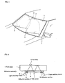
- a rain sensor 2 is attached upon an interior surface of the front window glass (windshield) 1 of an automobile with adhesive material (for example, adhesive tape) 3, located within a wiping area or region of one or more wipers 9 which wipe an outside surface thereof.
- the adhesive material (adhesive tape) 3 is selected to have a refractive index that is nearly equal to that of the window glass (i.e., 1.48).
- the window glass there is used a soda lime glass containing mainly SiO 2 , at a thickness of 5 mm.
- the rain sensor 2 comprises, as shown in Fig. 2, diffraction gratings 5 and 6 which are formed on a surface of a glass substrate 4 by the laser light.
- the adhesive material 3 is pasted all over the surface of the glass substrate 4 so as to closely contact the rain sensor 2 onto the front glass 1.
- light emitting means 7 comprising a light emitting element such as a light emitting diode (LED) or a laser diode (LD)
- a light receiving means 8 comprising a light receiving element such as a photo diode (PD).
- Light emitting means 7 and light receiving means 8 may be provided closely contacted with the diffraction gratings 5 and 6, respectively.
- the diffraction gratings 5 and 6 are preferably formed by an ablation phenomenon which is caused by irradiation of a laser beam upon the surface of the glass substrate 4.
- the diffraction gratings here comprise optical elements, such as minute or fine grooves that are formed on the surface of the glass substrate.
- the diffraction grating is designed to have a groove pitch ranging between 0.4 - 3 ⁇ m, depending upon various uses or purposes thereof.
- Diffraction gratings are mainly used to obtain a spectrum, and can also be used to divide or bend light by diffracting light, in particular in a case where monochromic light is used as a light source.
- a diffraction grating other than that mentioned above, other types of diffraction gratings may also be adopted, such as those of the reflection type, a type which comprises a slit in shape thereof, and further a type in which the refractive index thereof is varied periodically.
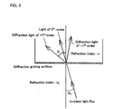
- the function which is utilized by the present invention is a phenomenon of the diffraction grating, wherein the diffraction light appears on a constant rule in the case where monochromatic light is incident thereupon.
- a primary (1 st order) diffraction lobe is generated at a constant angle with respect to the incident light.
- the primary diffraction light is mainly used because the higher ones have less light (i.e. are weaker in intensity).
- the relationship in angles between the incident light and the diffraction light can be expressed by the following equation (1).
- equation (1) clearly shows that the angle of the light traveling within the transparent plate can be adjusted by changing the incident angle of the light which is incident upon the diffraction grating.
- a diffraction grating it is possible to introduce light into the transparent plate at an arbitrary angle.
- the incident angle onto the diffraction grating it is also possible to have the introduced light undergo total internal reflection within the transparent plate.
- the light undergoing the total internal reflection within the transparent plate to exit to the outside, from within the transparent plate into the surrounding air.
- ⁇ and ⁇ 0 are the incident and the refracting angles with respect to a normal line at the boundary between surfaces of materials having refractive indexes n and n 0 ( ⁇ : incident angle, ⁇ 0 : refraction angle).
- the incident angle of the diffraction grating is adjusted. Namely, the incident angle upon the diffraction grating is calculated so as to obtain a reflection angle of 42.5° within the glass by using the above-mentioned equation (1).
- an incident angle of 22° can be obtained when using the primary plus (+1 st order) diffraction light lobe from a laser beam having a wavelength 633 nm emitted from a He-Ne laser.
- the incident angle upon the diffraction grating is 45° from the same calculation.
- the light is incident upon the diffraction grating 5 at an angle 45°. This light, which has undergone the total internal reflection at this time, exits from the other diffraction grating 6.
- the light exiting from the diffraction grating 6 will be reduced in intensity, in particular when water drops are adhered to or present upon a large number of total internal reflection points, then the output light is reduced by about 1/50.
- Note only one water drop W is shown in Fig. 2, although the number is actually more than 1. Namely, it can be confirmed that the presence of water on the surface of the glass can be detected with sufficient sensitivity and is reflected in the strength of the exiting light. Further, when the incident angle upon the diffraction grating is increased gradually, the same phenomenon also occurs.
- the incident angle comes to be greater than 64°, even though water drops adhere to or are present upon the points of total internal reflection, the exiting light does not change in intensity. This angle almost corresponds with the angle at which the condition of total internal reflection does not change irrespective of adhesion of presence of the water drops.
- the wiper controller apparatus comprises, as shown in Fig.
- a rain sensor 2 having a light emitting means for guiding or introducing the light into the front glass 1 in such a manner that it undergoes total internal reflection upon the inside surfaces thereof, a light receiving means 8 for receiving the light reflected within the front glass 1, and a wiper driver means 18 for driving the wiper 9 at a desired velocity based upon an output signal of the light receiving means 8.
- the light emitting means 7 comprises a light emitting element 10 such as a LED, LD and so on, a light receiving element 11 for detecting the light output from the light emitting element 10, such as a PD and so on, a driver circuit 12 for making the light emitting element 10 output a light beam modulated with a predetermined frequency, and a detector circuit 13 for receiving a signal corresponding to the modified component from the output light of the light receiving element 11. Also, the output signal of the detector circuit 13 is fed back to the driver circuit 12.
- a light emitting element 10 such as a LED, LD and so on
- a light receiving element 11 for detecting the light output from the light emitting element 10, such as a PD and so on
- a driver circuit 12 for making the light emitting element 10 output a light beam modulated with a predetermined frequency
- a detector circuit 13 for receiving a signal corresponding to the modified component from the output light of the light receiving element 11. Also, the output signal of the detector circuit 13 is fed back to the driver circuit 12.
- the light emitting means 7 since the signal corresponding to the modified component is received from the output signal of the light receiving element 11 by the detector circuit 13 and is fed back to the driver circuit 12 of the light emitting element 10, the output of light emission by the light emitting element 10 can be controlled to a desired value, and the output of light by the light emitting element 10 can be maintained at a desired value irrespective of any change in the ambient temperature of the light emitting means 7.
- the light receiving means 8 comprises a light receiving element 15 such as a PD and so on, a detector circuit 16 for taking out or receiving the signal corresponding to the modified component by the driver circuit 12 of the light emitting means 10, and an amplifier circuit 17 for amplifying an output signal of the detector circuit 16.
- the wiper controller apparatus Since the detector circuit 16 takes out or receives only the signal corresponding to the modified component generated at the light emitting means 10 from the output signal of the light receiving element 15 to be input into the wiper driver apparatus 20 through the amplifier circuit 17 and the controller circuit 19, the wiper controller apparatus will never be operated erroneously, even under the influence of outside ambient light, which can sometimes reach 150,000 lux under strong sunlight in mid-summer, though it may be only a few lux in darkness at midnight.
- the wiper driving means 18 comprises a controller circuit 19 for producing a desired signal from the output signal of the amplifier circuit 17, a wiper driver circuit 20 for converting the output signal of the controller circuit 19 into a wiper driving signal WD for driving the wiper(s) 9 at a desired velocity to be outputted to a wiper driving mechanism (not shown in the figure), and an auxiliary driver circuit 21 for making the wiper driver circuit 20 output a wiper driving signal WD1 that controls the wiper driving mechanism to perform only a single cycle of wiping action.
- the controller circuit 19 calculates and processes the output signal S of the amplifier circuit 17 to output three kinds of signals (i.e., to switch a first output signal D1, a second output signal D2, and a third output signal D3 into the "ON” condition).
- the "ON" condition means a high (H) level when it is positive in logic, while it turns to a low (L) level when negative, or "OFF".
- the output signal S of the amplifier circuit 17 is compared with three preset voltage levels sequentially from the highest one, i.e., a first preset level R1, a second preset level R2, and a third preset level R3.
- the rain sensor 2 which is used in the present invention, as previously mentioned, the more the water drops are adhered to or present upon the outside surface of the front glass 1, the lower the output signal level of the light receiving element 15. Therefore, the voltage level of the output signal S is at a maximum when no water drops are adhered to nor present upon the surface of the front glass, while it is at a minimum when many water drops are adhered to or present thereupon. In other words, the amount or degree of water drops that are present is detected.
- the first output signal is switched to the H level
- the second output signal D2 is switched to the H level when it is less or smaller than the second preset level R2 (S ⁇ R2)
- the third output signal D3 is switched to the H level when it is less or smaller than the third preset level R3 (S ⁇ R3).
- the first output signal D1 when the first output signal D1 is in the H level, it corresponds to a condition of drizzly or misty rain or a condition of light rain, when the second output signal D2 in the H level, it corresponds to a condition of mild rain, and when the third output signal D3 is in the H level, it corresponds to a condition of heavy rain.
- the source of the water drops is given as rain, the water drops may come to be present on the front windshield from other sources, for example, from heavy fog.
- the auxiliary driver circuit 21 makes the wiper driver circuit 20 output the wiper driving signal WD1 for driving the wiper by only one cycle when the time duration t of the wiper driving signal WD from the time when the wiper driving signal WD turns ON (into the "ON" condition) after initiation of the wiper 9 to when it comes to be equal to or longer than a predetermined time T (t ⁇ T), irrespective of the level of the output signal of the rain sensor 2.
- the predetermined time T for example, is preferably set to be around two (2) seconds, at the longest.
- auxiliary driver circuit 21 is also able to make the wiper driver circuit 20 output the wiper driving signal WD1 for driving the wiper by only one cycle again, even in the case where the wiper 9 was once initiated and then has completed only one complete cycle due to there being only a small amount of rainfall, after the predetermined time T has elapsed from the initial completed cycle, irrespective of the level of the output signal of the rain sensor 2.
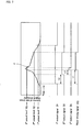
- the timing chart shown in Fig. 5 indicates the ON or OFF conditions of the output signals D1, D2 and D3 of the controller circuit 19 and the wiper driving signal WD with respect to changes in the amount V of water drops adhered to or present upon the front glass 1, during a time period starting from the time of initiating the wiper 9 when the rain starts to fall continuously thereafter until the time when the rain stops, in the case where the three kinds of output signals (the first output signal D1, the second output signal D2, and the third output signal D3) are produced by the controller circuit 19.
- V shown in Fig. 5 indicates the variations in the amount of water drops adhered or present upon the front glass 1, it corresponds to the reversed output signal S of the amplifier 17.
- the volume or amount of water drops also begins to increase. Further, when the amount of water present reaches the first preset level R1, the first output signal D1 is switched to the H level, and when the amount V of the rain drops further rises to reach the second preset level R2, the second output signal D2 is switched to the H level. Furthermore, when the volume or amount V of the water drops rises to reach the third preset level R3, the third output signal D3 is switched to the H level.
- the wiper driving signal WD is outputted from the wiper driver circuit 20, and the wiper 9 starts to be driven.
- the driving of the wiper 9 can be started after ejection of a predetermined amount of window washer liquid onto the front glass 1 or together with the ejection thereof.
- the wiper driving signal WD continues to be outputted as long as the second output signal D2 maintains the H level, and the wiper driver circuit 20 stops outputting of the wiper driving signal WD when the second output signal D2 is switched to the L level.
- the wiper 9 starts to be driven when the third output signal D3 is switched to the H level, and is stopped when the second output signal D2 is switched to the L level.
- the wiper 9 starts to be driven when the second output signal D2 is switched to the H level again even after it has already once been switched to the L level. Namely, if the first output signal D1 is maintained at the H level, the output condition of the wiper driving signal WD is determined depending upon that of the second output signal D2.
- the time duration t (the time of the "OFF" state or condition) of the wiper driving signal WD after having been previously switched into the "ON" condition comes to be equal to or greater than a predetermined time T (t ⁇ T) and the wiper driving signal WD1 for driving the wiper by one cycle is outputted from the wiper driver circuit 20 irrespective of the level of the output signal of the rain sensor 2.
- this wiper driving signal WD1 for single cycle driving of the wiper after the rain, it is possible to start driving the wiper 9 and to automatically wipe away remaining rain drops which are adhered or present upon the front glass 1 in an amount or volume less than the corresponding second preset level R2, or which are adhered or present but not detected by the rain sensor 2 and that have slid down into the view area of the front glass 1 from areas other than the wiping area wiped by the wiper 9.
- the wiper 9 is further driven by one additional cycle again when the predetermined time T elapses after the completion of the initial single cycle irrespective of the level of the output signal of the rain sensor 2. Therefore, it is possible to automatically wipe away the rain drops adhered or present upon the front glass 1 in a volume or amount less than the second preset level R2 and to start driving the wiper 9.
- the timing when the second output signal D2 is switched to the L level can be adjusted, thereby determining whether the front glass is to be wiped by the wiper , i.e., the time when the wiper 9 is to be stopped.
- the wiper 9 is driven again through the single cycle when the time duration t of the wiper driving signal WD comes to be equal to or greater than the predetermined time T irrespective of the level of the output signal of the rain sensor 2. Therefore, even small amounts of rain drops adhered or present upon the front glass 1 can be automatically wiped away.
- the wiper controller apparatus of the water drop sensitive type for the purpose of quickly responding to the situation of water drops becoming adhered to or present upon the window glass, free from any influence of ambient light, electromagnetic noise or the like from outside sources, which noise varies periodically, as shown in Fig. 6, comprises a rain sensor 2 including the light emitting means 7 for introducing the light into the front glass 1 so as to undergo total internal reflection upon the internal surface thereof, the light receiving means 8 for receiving the light reflected inside the front glass 1, and a wiper driver means 22 for driving the wiper or wipers 9 based upon the output signal of the light receiving means 8 at a desired velocity.
- the rain sensor 2 has the same construction and function as that shown in Fig. 4.
- the wiper driver means 22 comprises a noise remover or noise suppressor circuit 23 such as an integrator and so on, a controller circuit 24 for producing a desired signal from the output signal of the noise remover circuit 23, and a wiper driver circuit 25 which converts the output signal of the controller circuit 24 so as to output the wiper driving signal WD to the wiper driving mechanism (not shown in figure) for driving the wiper(s) 9 at the desired velocity.
- a noise remover or noise suppressor circuit 23 such as an integrator and so on
- a controller circuit 24 for producing a desired signal from the output signal of the noise remover circuit 23
- a wiper driver circuit 25 which converts the output signal of the controller circuit 24 so as to output the wiper driving signal WD to the wiper driving mechanism (not shown in figure) for driving the wiper(s) 9 at the desired velocity.
- the noise remover circuit 23 outputs a signal S2 only when the time duration (i.e., pulse width) of the output signal S1 of the amplifier circuit 17 exceeds a predetermined time T. Accordingly, the noise remover circuit 23 does not output the signal S2 with respect to any signal S1 which is less than the predetermined time T in signal duration time thereof.
- the predetermined time T in general, for responding to noise having a short signal duration time, is to be shorter than the driving frequency (cycle frequency) of the wiper (i.e., about 1 sec.) and is preferably longer than 0.3 sec.
- the predetermined time T can be preset by adjusting the time constant (CR) of the integrator circuit provided in the noise remover circuit 23.
- any periodically varying external ambient light or electromagnetic noise has a signal duration time of less than 0.3 sec. and falls onto the light emitting means 7, the wiper 9 will not be driven due to such noise since the noise remover circuit 23 removes those noise components and keeps them from being inputted into a lower stage of the circuitry, i.e., into the circuits 24 and 25.
- the controller circuit 24 calculates and processes the output signal S2 of the noise remover circuit 23 so as to output the three kinds of signals (i.e., switches the first output signal D1, the second output signal D2, and the third output signal D3 into the "ON” condition).
- the "ON" condition means a high (H) level if it is positive in logic, while it turns into a low (L) level when negative, or "OFF".
- the output signal S2 of the noise remover circuit 23 is also compared with the three preset voltage levels, sequentially from the highest one, i.e., the first preset level R1, the second preset level R2, and the third preset level R3.
- the voltage level of the output signal S2 is at a maximum when no water drops are adhered to nor present upon the surface of the front glass, while it is at a minimum when many water drops are adhered to or present thereupon.
- the first output signal is switched to the H level
- the second output signal P2 is switched to the H level when the output signal S2 is less or smaller than the second preset level R2 (S2 ⁇ R2)
- the third output signal P3 is switched to the H level when the output signal S2 is less or smaller than the third preset level R3 (S2 ⁇ R3).
- the first output signal D1 when the first output signal D1 is at the H level, this corresponds to a condition of drizzly or misty rain or a condition of light rain, when the second output signal D2 is at the H level, this corresponds to a condition of medium rain, and with the third output signal D3 in the H level, this corresponds to a condition of heavy rain.
- the timing chart shown in Fig. 7 also indicates the ON or OFF conditions of the output signals D1, D2, and D3 of the controller circuit 24 and the wiper driving signal WP with respect to changes or variations in the volume or amount V of water drops adhered to or present upon the front glass 1, during a time period starting from initiation of the wiper 9 when rain starts falling continuously thereafter until the time when the rain stops, in the case where the three kinds of output signals (the first output signal D1, the second output signal D2, and the third output signal D3) are produced by the controller circuit 24.
- V shown in Fig. 7 indicates the changing volumes or amounts of rain drops adhered to or present upon the front glass 1, it corresponds to the reversed output signal S2 of the noise remover circuit 23.
- the volume or amount of water drops also begins to increase. Further, when the amount of water drops reaches the first preset level R1, the first output signal D1 is switched to the H level, and when the volume V of the rain drops further increases to reach the second preset level R2, the second output signal D2 is switched to the H level. Furthermore, when the amount V of water drops increases to reach the third preset level R3, the third output signal D3 is switched to the H level.
- the wiper driving signal WD is outputted from the wiper driver circuit 25, and the wiper 9 starts to be driven.
- the driving of the wiper 9 can also be started after ejection of a predetermined amount of window washer liquid onto the front glass 1 or together with the ejection thereof.
- the wiper driving signal WD continues to be outputted as long as the second output signal D2 is maintained at the H level, and the wiper driver circuit 25 stops outputting of the wiper driving signal WD when the second output signal D2 is switched to the L level.
- the wiper 9 starts to be driven when the third output signal D3 is switched to the H level, and is stopped when the second output signal D2 is switched to the L level.
- the time when the second output signal D2 is switched to the L level can be adjusted, thereby determining whether the front glass is still to be wiped by the wiper, i.e., the time when the wiper 9 to be stopped.
- the output signal S2 of the noise remover circuit 23 is compared with four preset voltage levels, sequentially from the highest one, i.e., the first preset level R1, the second preset level R2, the third preset level R3, and the fourth preset level R4.
- the first output signal D1 is switched to the H level
- the second output signal D2 is switched to the H level when the output signal S2 is less or smaller than the second preset level R2 (S2 ⁇ R2)
- the third output signal D3 is switched to the H level when the output signal S2 is less or smaller than the third preset level R3 (S2 ⁇ R3)
- the fourth output signal D4 is switched to the H level when the output signal S2 is less or smaller than the fourth preset level R4 (S2 ⁇ R4).
- the case where the first output signal D1 to the third output signal D3 are at the H level corresponds to the rain conditions mentioned above, and the case where the fourth output signal D4 is switched to the H level corresponds to a situation where the rain is falling harder than that of the case where the third output signal is at the H level.
- the timing chart shown in Fig. 8 indicates the ON or OFF conditions of the output signals D1, D2, D3, and D4 of the controller circuit 24 and the wiper driving signal WD with respect to changes or variations in the volume or amount V of water drops adhered to or present upon the front glass 1, during a time period starting from initiation of the wiper 9 when the rain starts to fall continuously thereafter until the time when the rain stops, in the case where the four kinds of output signals (the first output signal D1, the second output signal D2, the third output signal D3, and the fourth output signal D4) are produced by the controller circuit 24.
- V shown in Fig. 8 indicates the changing volumes or amounts of rain drops adhered to or present upon the front glass 1 in the same manner as in Fig. 7, it corresponds to the reversed output signal S2 of the noise remover circuit 23.
- the volume or amount of water drops also begins to increase. Further, when the volume or amount of water drops reaches the first preset level R1, the first output signal D1 is switched to the H level, when the amount V of rain drops further increases to reach the second preset level R2, the second output signal D2 is switched to the H level, and when the volume V of rain drops further reaches to the third preset level R3, the third output signal D2 is switched to the H level. Furthermore, when the quantity V of the water drops increases up to reach the fourth preset level R4, the fourth output signal D4 is switched to the H level.
- the wiper driving signal WD is outputted from the wiper driver circuit 25, and the wiper 9 starts to be driven.
- the driving of the wiper 9 can be started after ejection of a predetermined amount of window washer liquid onto the front glass 1 or together with the ejection thereof.
- the wiper 9 is driven at a high velocity.
- the wiper driving signal WD continues to be outputted as long as the second output signal D2 is at the H level, even if the third output signal D3 is switched to L level, and when the second output signal D2 is switched to the L level, the wiper driver circuit 21 stops outputting of the wiper driving signal WD.
- the wiper 9 starts to be driven when the third output signal D3 is switched to the H level, and is stopped when the second output signal D2 is switched to the L level.
- the wiper is driven at a high velocity when the fourth output signal D4 is maintained at the H level.
- the timing when the second output signal D2 is switched to the L level can be adjusted, thereby determining whether the front glass is to be wiped by the wiper based on the time when the wiper 9 is stopped.
- application of the wiper controller apparatus of the water drop sensitive type according to the present invention should not be limited only to the front glass (windshield) 1 of an automobile as mentioned above. I can also be applied to a rear window glass thereof, or to the window glass of any other vehicle or structure that is exposed to the elements (rain, fog, etc.).
Landscapes
- Engineering & Computer Science (AREA)
- Automation & Control Theory (AREA)
- Mechanical Engineering (AREA)
- Investigating Or Analysing Materials By Optical Means (AREA)
Applications Claiming Priority (4)
| Application Number | Priority Date | Filing Date | Title |
|---|---|---|---|
| JP9347749A JPH11170982A (ja) | 1997-12-17 | 1997-12-17 | 水滴感応式ワイパ制御装置 |
| JP9347748A JPH11170983A (ja) | 1997-12-17 | 1997-12-17 | 水滴感応式ワイパ制御装置 |
| JP34774897 | 1997-12-17 | ||
| JP34774997 | 1997-12-17 |
Publications (2)
| Publication Number | Publication Date |
|---|---|
| EP0926026A2 true EP0926026A2 (fr) | 1999-06-30 |
| EP0926026A3 EP0926026A3 (fr) | 2001-04-25 |
Family
ID=26578600
Family Applications (1)
| Application Number | Title | Priority Date | Filing Date |
|---|---|---|---|
| EP98310361A Withdrawn EP0926026A3 (fr) | 1997-12-17 | 1998-12-17 | Commande d'essuie-glace répondant à la présence d'eau |
Country Status (3)
| Country | Link |
|---|---|
| US (1) | US6239570B1 (fr) |
| EP (1) | EP0926026A3 (fr) |
| KR (1) | KR19990063055A (fr) |
Cited By (2)
| Publication number | Priority date | Publication date | Assignee | Title |
|---|---|---|---|---|
| WO2001081134A1 (fr) * | 2000-04-26 | 2001-11-01 | Robert Bosch Gmbh | Procede de commande d"un moteur d"essuie-glace |
| GB2471674A (en) * | 2009-07-07 | 2011-01-12 | Nissan Motor Mfg | A wash-wipe system for a vehicle transparent member |
Families Citing this family (7)
| Publication number | Priority date | Publication date | Assignee | Title |
|---|---|---|---|---|
| DE19756502C2 (de) * | 1997-11-07 | 1999-12-16 | Daimler Chrysler Ag | Steuereinrichtung für eine Scheibenwischereinrichtung |
| DE19756504B4 (de) * | 1997-12-19 | 2004-04-15 | Daimlerchrysler Ag | Steuereinrichtung für eine Scheibenwischereinrichtung |
| JP4259917B2 (ja) * | 2003-05-15 | 2009-04-30 | ナイルス株式会社 | ワイパー制御方法、およびワイパー制御装置 |
| JP4175266B2 (ja) * | 2004-02-06 | 2008-11-05 | 株式会社デンソー | ワイパ装置 |
| JP4905097B2 (ja) * | 2006-12-06 | 2012-03-28 | 株式会社デンソー | 雨滴検出装置 |
| US9475464B2 (en) * | 2009-07-09 | 2016-10-25 | Ford Global Technologies, Llc | Sensor system and method for a vehicle |
| DE102017206480B3 (de) * | 2017-04-18 | 2018-06-14 | Audi Ag | Verfahren zum Betreiben eines kapazitiven Regensensors eines Kraftfahrzeugs, Messsignalentstörungsvorrichtung und Kraftfahrzeug mit einer derartigen Messsignalentstörungsvorrichtung |
Citations (1)
| Publication number | Priority date | Publication date | Assignee | Title |
|---|---|---|---|---|
| JPH0267945A (ja) | 1988-09-01 | 1990-03-07 | Honda Motor Co Ltd | ウインドガラスの水滴検出装置 |
Family Cites Families (7)
| Publication number | Priority date | Publication date | Assignee | Title |
|---|---|---|---|---|
| JPH02139165U (fr) * | 1989-04-24 | 1990-11-20 | ||
| DE3937920A1 (de) * | 1989-11-15 | 1991-05-16 | Bosch Gmbh Robert | Vorrichtung zur automatischen steuerung von kraftfahrzeug-scheibenwischer |
| JPH06328998A (ja) * | 1993-05-21 | 1994-11-29 | Honda Motor Co Ltd | ワイパ自動制御装置 |
| AU6968394A (en) * | 1993-07-02 | 1995-01-24 | Gerd Reime | Device for controlling a windscreen-washer installation |
| JP3643393B2 (ja) * | 1994-11-30 | 2005-04-27 | 富士通テン株式会社 | ワイパ制御装置 |
| DE19519500C2 (de) * | 1995-05-27 | 1998-12-24 | Bosch Gmbh Robert | Vorrichtung zum Betreiben eines Scheibenwischers |
| DE19603553C1 (de) * | 1996-02-01 | 1997-04-03 | Bosch Gmbh Robert | Vorrichtung zum Betreiben eines Scheibenwischers |
-
1998
- 1998-12-15 KR KR1019980054964A patent/KR19990063055A/ko not_active Application Discontinuation
- 1998-12-16 US US09/211,286 patent/US6239570B1/en not_active Expired - Fee Related
- 1998-12-17 EP EP98310361A patent/EP0926026A3/fr not_active Withdrawn
Patent Citations (1)
| Publication number | Priority date | Publication date | Assignee | Title |
|---|---|---|---|---|
| JPH0267945A (ja) | 1988-09-01 | 1990-03-07 | Honda Motor Co Ltd | ウインドガラスの水滴検出装置 |
Cited By (3)
| Publication number | Priority date | Publication date | Assignee | Title |
|---|---|---|---|---|
| WO2001081134A1 (fr) * | 2000-04-26 | 2001-11-01 | Robert Bosch Gmbh | Procede de commande d"un moteur d"essuie-glace |
| US6825629B2 (en) | 2000-04-26 | 2004-11-30 | Robert Bosch Gmbh | Method of controlling a wiper motor |
| GB2471674A (en) * | 2009-07-07 | 2011-01-12 | Nissan Motor Mfg | A wash-wipe system for a vehicle transparent member |
Also Published As
| Publication number | Publication date |
|---|---|
| US6239570B1 (en) | 2001-05-29 |
| EP0926026A3 (fr) | 2001-04-25 |
| KR19990063055A (ko) | 1999-07-26 |
Similar Documents
| Publication | Publication Date | Title |
|---|---|---|
| EP0916558A2 (fr) | Dispositif de détection d'eau pour un substrat transparent | |
| EP0893319A2 (fr) | Dispositif de contrÔle d'essuie-glace | |
| US7718943B2 (en) | Moisture sensor for optically detecting moisture | |
| EP1798540A2 (fr) | Capteur d'objets et appareil de contrôle l'utilisant | |
| US6397161B1 (en) | Method for stabilizing output of rain sensor and protection method therefor | |
| US20110128543A1 (en) | Rain sensor using light scattering | |
| US6239570B1 (en) | Wiper controller apparatus of water drop sensitive type | |
| JP2003254897A (ja) | 雨滴及び光検出装置、及び、オートワイパー装置 | |
| KR19990082870A (ko) | 물방울 검출센서 | |
| US7034932B2 (en) | Deposit detector and controller using the detector | |
| EP0866330A2 (fr) | Substrat transparent pour la détection de liquides | |
| EP0919443A2 (fr) | Substrat transparent équipé d'un dispositif de détection d'eau | |
| EP0893318A2 (fr) | Substrat transparent avec détecteur de gouttes d'eau et méthode de génération des signeaux et méthode de stabilisation des signeaux de sortie pour un tel détecteur | |
| EP0957017A2 (fr) | Détecteur de liquide | |
| JPH09257952A (ja) | 結露および雨滴検出センサとその検出方法 | |
| AU648513B2 (en) | Sensing moisture on screen and automated controlled wiping | |
| JP2007511750A (ja) | ガラス、例えば自動車のフロントガラスに対するレインセンサ | |
| EP0982205A2 (fr) | Appareil et procédé de détection d'un liquide | |
| US7589836B2 (en) | Optoelectronic sensor device | |
| JPH11170983A (ja) | 水滴感応式ワイパ制御装置 | |
| JPS59106348A (ja) | ワイパ自動制御装置 | |
| JPH11170982A (ja) | 水滴感応式ワイパ制御装置 | |
| JP3066725B2 (ja) | 水滴検出装置 | |
| JPH11326186A (ja) | レインセンサの温度特性補正方法 | |
| JPH11183369A (ja) | レインセンサの温度補償方法 |
Legal Events
| Date | Code | Title | Description |
|---|---|---|---|
| PUAI | Public reference made under article 153(3) epc to a published international application that has entered the european phase |
Free format text: ORIGINAL CODE: 0009012 |
|
| AK | Designated contracting states |
Kind code of ref document: A2 Designated state(s): AT BE CH CY DE DK ES FI FR GB GR IE IT LI LU MC NL PT SE |
|
| AX | Request for extension of the european patent |
Free format text: AL;LT;LV;MK;RO;SI |
|
| PUAL | Search report despatched |
Free format text: ORIGINAL CODE: 0009013 |
|
| AK | Designated contracting states |
Kind code of ref document: A3 Designated state(s): AT BE CH CY DE DK ES FI FR GB GR IE IT LI LU MC NL PT SE |
|
| AX | Request for extension of the european patent |
Free format text: AL;LT;LV;MK;RO;SI |
|
| AKX | Designation fees paid | ||
| REG | Reference to a national code |
Ref country code: DE Ref legal event code: 8566 |
|
| STAA | Information on the status of an ep patent application or granted ep patent |
Free format text: STATUS: THE APPLICATION IS DEEMED TO BE WITHDRAWN |
|
| 18D | Application deemed to be withdrawn |
Effective date: 20011026 |