EP0925249B1 - Active disk guide - Google Patents
Active disk guide Download PDFInfo
- Publication number
- EP0925249B1 EP0925249B1 EP96926122A EP96926122A EP0925249B1 EP 0925249 B1 EP0925249 B1 EP 0925249B1 EP 96926122 A EP96926122 A EP 96926122A EP 96926122 A EP96926122 A EP 96926122A EP 0925249 B1 EP0925249 B1 EP 0925249B1
- Authority
- EP
- European Patent Office
- Prior art keywords
- shaft
- component
- angle
- conveyor system
- conveying means
- Prior art date
- Legal status (The legal status is an assumption and is not a legal conclusion. Google has not performed a legal analysis and makes no representation as to the accuracy of the status listed.)
- Expired - Lifetime
Links
Images

Classifications
-
- B—PERFORMING OPERATIONS; TRANSPORTING
- B65—CONVEYING; PACKING; STORING; HANDLING THIN OR FILAMENTARY MATERIAL
- B65G—TRANSPORT OR STORAGE DEVICES, e.g. CONVEYORS FOR LOADING OR TIPPING, SHOP CONVEYOR SYSTEMS OR PNEUMATIC TUBE CONVEYORS
- B65G39/00—Rollers, e.g. drive rollers, or arrangements thereof incorporated in roller-ways or other types of mechanical conveyors
- B65G39/10—Arrangements of rollers
- B65G39/12—Arrangements of rollers mounted on framework
- B65G39/16—Arrangements of rollers mounted on framework for aligning belts or chains
-
- B—PERFORMING OPERATIONS; TRANSPORTING
- B65—CONVEYING; PACKING; STORING; HANDLING THIN OR FILAMENTARY MATERIAL
- B65G—TRANSPORT OR STORAGE DEVICES, e.g. CONVEYORS FOR LOADING OR TIPPING, SHOP CONVEYOR SYSTEMS OR PNEUMATIC TUBE CONVEYORS
- B65G39/00—Rollers, e.g. drive rollers, or arrangements thereof incorporated in roller-ways or other types of mechanical conveyors
- B65G39/02—Adaptations of individual rollers and supports therefor
- B65G39/07—Other adaptations of sleeves
- B65G39/071—Other adaptations of sleeves for aligning belts or sheets
-
- B—PERFORMING OPERATIONS; TRANSPORTING
- B65—CONVEYING; PACKING; STORING; HANDLING THIN OR FILAMENTARY MATERIAL
- B65H—HANDLING THIN OR FILAMENTARY MATERIAL, e.g. SHEETS, WEBS, CABLES
- B65H23/00—Registering, tensioning, smoothing or guiding webs
- B65H23/02—Registering, tensioning, smoothing or guiding webs transversely
- B65H23/032—Controlling transverse register of web
- B65H23/038—Controlling transverse register of web by rollers
-
- B—PERFORMING OPERATIONS; TRANSPORTING
- B65—CONVEYING; PACKING; STORING; HANDLING THIN OR FILAMENTARY MATERIAL
- B65H—HANDLING THIN OR FILAMENTARY MATERIAL, e.g. SHEETS, WEBS, CABLES
- B65H2801/00—Application field
- B65H2801/93—Tyres
Definitions
- the present invention concerns the art of methods and apparatuses for guiding strip components on a conveyor system, and more specifically to methods and apparatuses for electronically sensing and dynamically shifting and steering the strip components to a desired transverse position.
- the conveyor system either did not guide the component to align it with the conveyor, or the conveyor system had guides that kept the component aligned with the conveyor. If the component was not guided, it was possible that the component would not be aligned with the conveyor when the component reached its destination. If physical guides such as side guide rails were used, the sides of the component were subject to damage due to contact with the guide rails.
- a belt roller utilized an assembly of angled disks rotatably mounted on a rotatable shaft to maintain the position of a belt.
- the shaft was rotated, the angle of engagement of the disks with the belt surface was changed.
- One embodiment of the invention used a sensing device to measure belt displacement.
- this assembly of angled disks was unable to provide an instantaneous lateral adjustment. Lateral movement of the assembly was not necessary because the belt was wrapped around a significant portion of the disks which allowed more contact time with the belt to steer the belt.
- a conveyor system for strip components such an apparatus would contact the strip component to be guided along a small portion of each disk, thereby reducing the contact time for guiding and seriously limit the steering capability of the system.
- the present invention contemplates a new and improved guiding system which is compact, simple in design, effective in use, and solves the problem by overcoming the foregoing difficulties and others while providing better and more advantageous overall results.
- a conveyor system a method and a disk guide apparatus for steering and conveying an associated strip component on a conveying means are provided as defined in the appended claims.
- One advantage of the present invention is that axial movement of the shaft provides instantaneous lateral adjustments in the position of the strip component.
- Another advantage of the present invention is that the component is guided from the bottom of the component only, thereby not damaging the sides of the component.
- Another advantage of the present invention is that the position of the component is determined without contacting and damaging the edges of the component.
- Another advantage of the present invention is that a continuous component may be guided without damaging the component.
- Another advantage of the present invention is that the shaft turning apparatus is compact and provides both steering and shifting of the disk guide.
- the disk guide may guide a series of individual components.
- Another advantage of the present invention is that it is operable with a minimum web tension of the strip or sheet component.
- Figure 1 shows a plan view of a conveyor system 10 that includes an active disk guide 16.
- the conveyor system preferably has a conveyor belt 22 to convey a strip or sheet component 28 such as a strip or sheet of rubber from an extruder to an applicator.
- the active disk guide 16 located beyond an end 34 of the conveyor belt 22, centers the component 28 along a center line 40 of the conveyor belt 22 by an optical edge sensor 46.
- the optical sensor 46 senses the position of an edge 52 of the component relative to the conveyor.
- the optical sensor 46 is positioned to detect whether the edge 52 of the component 28 is outside a predetermined position that is based upon the width of the component.
- the optical sensor 46 is connected to a control apparatus, which operates the active disk guide 16.
- the active disk guide 16 may be used to steer the component 28, thereby aligning the component with the center line 40 of the conveyor belt 22.
- This edge guiding may be replaced by a center guiding system which requires another optical sensor at an opposite edge of the component 28.
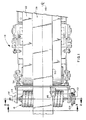
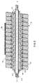
- the active disk guide 16 includes a shaft 64 and a series of disks 70.
- Each of the disks 70 is rotatably mounted on a hearing 82 and tilted or canted at an angle 76 slightly less than 90 degrees.
- the disks 70 are tilted at an angle of 85 degrees with respect to the axis A-A of the shaft 64, although a wider range of angles may also be employed, preferably between 30 and 89 degrees.
- the orientation of the disks 70 changes, ranging from being tilted to the right as shown in Figure 2 to being tilted in the opposite direction.
- the disks 70 maintain their fixed angle 76 with respect to the shaft axis A-A.
- Each of the disks 70 preferably includes an inner bearing 88 and an outer disk 94.
- the inner bearing 88 is mounted on the shaft 64 for rotation with the shaft as by keys (not shown), and the outer disk 94 is rotatably supported on the inner bearing 88.
- the bearing 88 permits the free and independent rotation of the outer disk 94 about the shaft 64.
- one end 106 of the shaft 64 is preferably threaded.
- the threaded end 106 is screwed into a stationery threaded bushing 110 mounted on a frame member 114.
- a servo motor 118 which is also mounted on another frame member 116 has a pulley for moving a belt 124 wrapped around a second pulley 112 mounted on the shaft 64. Rotation of the motor 118 causes rotation of the shaft 64 changing the orientation of the disks 70 and causes the strip component 28 to be steered. Because the shaft 64 is threaded in the hushing 110, rotation of the pulley 112 also causes the shaft to be moved in an axial direction the distance the threaded end 106 is moved due to rotation of the pulley.
- the threads at the threaded end 106 of the shaft 64 are preferably at a one degree pitch.
- the shaft 64 preferably begins at a neutral position and rotates about the axis A-A 90 degrees in each direction, thereby causing the disk guide 16 to go from a neutral position to full steer right or full steer left. Turning of the shaft 64 over an angle of 90 degrees also moves the shaft axially one quarter of an inch because the shaft end 106 is threaded in the bushing 110.
- the immediate axial movement of the shaft 64 enables the strip component 28 to be moved transversely as the strip component passes over the active disk guide 16.
- Servo motor 118 acts in response to signals from the control apparatus based upon the location of the component 28 as determined by the optical sensor 46.
- the active disk guide 16 may also be used with a conveyor system 10 that consists solely of rollers that allows the strip component 28 to roll with the aid of gravity, or any other suitable conveyor system.
Landscapes
- Engineering & Computer Science (AREA)
- Mechanical Engineering (AREA)
- Registering, Tensioning, Guiding Webs, And Rollers Therefor (AREA)
- Control Of Conveyors (AREA)
- Structure Of Belt Conveyors (AREA)
- Tires In General (AREA)
- Registering Or Overturning Sheets (AREA)
- Primary Cells (AREA)
- Tyre Moulding (AREA)
Applications Claiming Priority (1)
| Application Number | Priority Date | Filing Date | Title |
|---|---|---|---|
| PCT/US1996/012178 WO1998004488A1 (en) | 1996-07-25 | 1996-07-25 | Active disk guide |
Publications (2)
| Publication Number | Publication Date |
|---|---|
| EP0925249A1 EP0925249A1 (en) | 1999-06-30 |
| EP0925249B1 true EP0925249B1 (en) | 2003-01-02 |
Family
ID=22255505
Family Applications (1)
| Application Number | Title | Priority Date | Filing Date |
|---|---|---|---|
| EP96926122A Expired - Lifetime EP0925249B1 (en) | 1996-07-25 | 1996-07-25 | Active disk guide |
Country Status (11)
| Country | Link |
|---|---|
| EP (1) | EP0925249B1 (pt) |
| JP (1) | JP3785192B2 (pt) |
| AU (1) | AU6628296A (pt) |
| BR (1) | BR9612672A (pt) |
| CA (1) | CA2261699A1 (pt) |
| DE (1) | DE69625621T2 (pt) |
| ES (1) | ES2188772T3 (pt) |
| PL (1) | PL331318A1 (pt) |
| TW (1) | TW344736B (pt) |
| WO (1) | WO1998004488A1 (pt) |
| ZA (1) | ZA976195B (pt) |
Families Citing this family (3)
| Publication number | Priority date | Publication date | Assignee | Title |
|---|---|---|---|---|
| US6488193B1 (en) | 1998-02-18 | 2002-12-03 | The Goodyear Tire & Rubber Co. | Guide conveyor having a laterally adjustable deflector roller at the end |
| CA2315714A1 (en) * | 1998-02-18 | 1999-08-26 | Mark Daniel Banas | Guide conveyor having a laterally adjustable deflector roller at the end |
| TWI490480B (zh) * | 2012-10-09 | 2015-07-01 | Utechzone Co Ltd | A turning device, a detecting device having the inverting device, and a turning method |
Family Cites Families (7)
| Publication number | Priority date | Publication date | Assignee | Title |
|---|---|---|---|---|
| GB954976A (en) * | 1959-10-10 | 1964-04-08 | Dunlop Rubber Co | Correction device for travelling continuous material |
| US3244418A (en) * | 1963-11-26 | 1966-04-05 | James G Henderson | Edge sensing device |
| US3273696A (en) * | 1965-01-27 | 1966-09-20 | Improved Machinery Inc | Belt positioning device |
| FR1441479A (fr) * | 1965-01-29 | 1966-06-10 | Erhardt & Leimer Ohg | Dispositif pour le guidage ou le décalage latéral de bandes de marchandise en mouvement, par exemple de bandes de produits textiles |
| DE8025417U1 (de) * | 1980-09-23 | 1981-12-03 | Elektro-Mechanik Gmbh, 5963 Wenden | Steuerrolle zur korrektur der seitenlage laufender baender |
| EP0110670B1 (en) * | 1982-11-24 | 1988-01-13 | Xerox Corporation | Laterally translatable roll apparatus |
| US5244435A (en) * | 1992-07-24 | 1993-09-14 | Ronald Billett | Reversing axes belt steering pulley |
-
1996
- 1996-07-25 AU AU66282/96A patent/AU6628296A/en not_active Abandoned
- 1996-07-25 ES ES96926122T patent/ES2188772T3/es not_active Expired - Lifetime
- 1996-07-25 BR BR9612672A patent/BR9612672A/pt not_active IP Right Cessation
- 1996-07-25 CA CA002261699A patent/CA2261699A1/en not_active Abandoned
- 1996-07-25 JP JP50874298A patent/JP3785192B2/ja not_active Expired - Fee Related
- 1996-07-25 WO PCT/US1996/012178 patent/WO1998004488A1/en active IP Right Grant
- 1996-07-25 DE DE69625621T patent/DE69625621T2/de not_active Expired - Fee Related
- 1996-07-25 PL PL96331318A patent/PL331318A1/xx unknown
- 1996-07-25 EP EP96926122A patent/EP0925249B1/en not_active Expired - Lifetime
-
1997
- 1997-07-11 ZA ZA9706195A patent/ZA976195B/xx unknown
- 1997-07-21 TW TW086110342A patent/TW344736B/zh active
Also Published As
| Publication number | Publication date |
|---|---|
| PL331318A1 (en) | 1999-07-05 |
| EP0925249A1 (en) | 1999-06-30 |
| TW344736B (en) | 1998-11-11 |
| BR9612672A (pt) | 1999-07-20 |
| DE69625621T2 (de) | 2003-11-20 |
| CA2261699A1 (en) | 1998-02-05 |
| DE69625621D1 (de) | 2003-02-06 |
| ZA976195B (en) | 1998-02-03 |
| WO1998004488A1 (en) | 1998-02-05 |
| JP2000515838A (ja) | 2000-11-28 |
| JP3785192B2 (ja) | 2006-06-14 |
| AU6628296A (en) | 1998-02-20 |
| ES2188772T3 (es) | 2003-07-01 |
Similar Documents
| Publication | Publication Date | Title |
|---|---|---|
| US5558263A (en) | Apparatus and method for non-contact active tensioning and steering of moving webs | |
| JP2851533B2 (ja) | シングルフェーサ | |
| US4343422A (en) | Apparatus for deflecting a moving web of material | |
| US4863087A (en) | Guide apparatus for elongated flexible web | |
| US6450381B1 (en) | Device and method for guiding a transversely stable material web | |
| US6550656B2 (en) | Device for spreading, compressing and guiding a running material web | |
| US5184424A (en) | Self correcting belt tracking apparatus for widebelt abrasive grinding machine | |
| US6062453A (en) | Active disk guide | |
| AU743325B2 (en) | Strip guiding apparatus and associated method for maintaining lateral position | |
| EP0925249B1 (en) | Active disk guide | |
| US5047003A (en) | Apparatus for zigzag folding a paper web | |
| US3390823A (en) | Web guide apparatus | |
| US6257964B1 (en) | Roll grinding system for a roll | |
| US4155496A (en) | Web control device | |
| US5244435A (en) | Reversing axes belt steering pulley | |
| KR100314701B1 (ko) | 포장 장치 | |
| KR100470624B1 (ko) | 컨베이어 시스템, 및 관련 스트립 요소를 반송 및 조종하는 방법 | |
| US4656702A (en) | Expander and guider roller | |
| CA2419286C (en) | Belt alignment system | |
| MXPA99000813A (en) | Active disk guide | |
| EP1060112B1 (en) | Guide conveyor having a laterally adjustable deflector roller at the end | |
| WO2003068638A1 (en) | Conveyor belt training idler roller and installations including same | |
| US5367352A (en) | Direction-changing roller for suspension frames of photographic material developing machines | |
| KR101023112B1 (ko) | 진행 스트립의 쏠림 교정장치 | |
| US4674667A (en) | Apparatus for correcting the lateral displacement of a moving metallic sheet |
Legal Events
| Date | Code | Title | Description |
|---|---|---|---|
| PUAI | Public reference made under article 153(3) epc to a published international application that has entered the european phase |
Free format text: ORIGINAL CODE: 0009012 |
|
| 17P | Request for examination filed |
Effective date: 19990114 |
|
| AK | Designated contracting states |
Kind code of ref document: A1 Designated state(s): DE ES FR GB IT |
|
| 17Q | First examination report despatched |
Effective date: 20000808 |
|
| GRAG | Despatch of communication of intention to grant |
Free format text: ORIGINAL CODE: EPIDOS AGRA |
|
| GRAG | Despatch of communication of intention to grant |
Free format text: ORIGINAL CODE: EPIDOS AGRA |
|
| GRAH | Despatch of communication of intention to grant a patent |
Free format text: ORIGINAL CODE: EPIDOS IGRA |
|
| GRAH | Despatch of communication of intention to grant a patent |
Free format text: ORIGINAL CODE: EPIDOS IGRA |
|
| GRAA | (expected) grant |
Free format text: ORIGINAL CODE: 0009210 |
|
| STAA | Information on the status of an ep patent application or granted ep patent |
Free format text: STATUS: THE PATENT HAS BEEN GRANTED |
|
| AK | Designated contracting states |
Kind code of ref document: B1 Designated state(s): DE ES FR GB IT |
|
| REG | Reference to a national code |
Ref country code: GB Ref legal event code: FG4D Free format text: 20030102 |
|
| REF | Corresponds to: |
Ref document number: 69625621 Country of ref document: DE Date of ref document: 20030206 Kind code of ref document: P |
|
| ET | Fr: translation filed | ||
| REG | Reference to a national code |
Ref country code: ES Ref legal event code: FG2A Ref document number: 2188772 Country of ref document: ES Kind code of ref document: T3 |
|
| PLBE | No opposition filed within time limit |
Free format text: ORIGINAL CODE: 0009261 |
|
| 26N | No opposition filed |
Effective date: 20031003 |
|
| PGFP | Annual fee paid to national office [announced via postgrant information from national office to epo] |
Ref country code: GB Payment date: 20060614 Year of fee payment: 11 |
|
| PGFP | Annual fee paid to national office [announced via postgrant information from national office to epo] |
Ref country code: FR Payment date: 20060705 Year of fee payment: 11 |
|
| PGFP | Annual fee paid to national office [announced via postgrant information from national office to epo] |
Ref country code: ES Payment date: 20060719 Year of fee payment: 11 |
|
| PGFP | Annual fee paid to national office [announced via postgrant information from national office to epo] |
Ref country code: IT Payment date: 20060731 Year of fee payment: 11 Ref country code: DE Payment date: 20060731 Year of fee payment: 11 |
|
| GBPC | Gb: european patent ceased through non-payment of renewal fee |
Effective date: 20070725 |
|
| PG25 | Lapsed in a contracting state [announced via postgrant information from national office to epo] |
Ref country code: DE Free format text: LAPSE BECAUSE OF NON-PAYMENT OF DUE FEES Effective date: 20080201 |
|
| PG25 | Lapsed in a contracting state [announced via postgrant information from national office to epo] |
Ref country code: GB Free format text: LAPSE BECAUSE OF NON-PAYMENT OF DUE FEES Effective date: 20070725 |
|
| REG | Reference to a national code |
Ref country code: FR Ref legal event code: ST Effective date: 20080331 |
|
| PG25 | Lapsed in a contracting state [announced via postgrant information from national office to epo] |
Ref country code: FR Free format text: LAPSE BECAUSE OF NON-PAYMENT OF DUE FEES Effective date: 20070731 |
|
| REG | Reference to a national code |
Ref country code: ES Ref legal event code: FD2A Effective date: 20070726 |
|
| PG25 | Lapsed in a contracting state [announced via postgrant information from national office to epo] |
Ref country code: ES Free format text: LAPSE BECAUSE OF NON-PAYMENT OF DUE FEES Effective date: 20070726 |
|
| PG25 | Lapsed in a contracting state [announced via postgrant information from national office to epo] |
Ref country code: IT Free format text: LAPSE BECAUSE OF NON-PAYMENT OF DUE FEES Effective date: 20070725 |