EP0924735A2 - Agencement de fusibles - Google Patents
Agencement de fusibles Download PDFInfo
- Publication number
- EP0924735A2 EP0924735A2 EP98203980A EP98203980A EP0924735A2 EP 0924735 A2 EP0924735 A2 EP 0924735A2 EP 98203980 A EP98203980 A EP 98203980A EP 98203980 A EP98203980 A EP 98203980A EP 0924735 A2 EP0924735 A2 EP 0924735A2
- Authority
- EP
- European Patent Office
- Prior art keywords
- heating element
- switch
- fuse arrangement
- electrical
- sensor
- Prior art date
- Legal status (The legal status is an assumption and is not a legal conclusion. Google has not performed a legal analysis and makes no representation as to the accuracy of the status listed.)
- Withdrawn
Links
Images
Classifications
-
- H—ELECTRICITY
- H01—ELECTRIC ELEMENTS
- H01H—ELECTRIC SWITCHES; RELAYS; SELECTORS; EMERGENCY PROTECTIVE DEVICES
- H01H85/00—Protective devices in which the current flows through a part of fusible material and this current is interrupted by displacement of the fusible material when this current becomes excessive
- H01H85/02—Details
- H01H85/46—Circuit arrangements not adapted to a particular application of the protective device
- H01H2085/466—Circuit arrangements not adapted to a particular application of the protective device with remote controlled forced fusing
-
- H—ELECTRICITY
- H01—ELECTRIC ELEMENTS
- H01H—ELECTRIC SWITCHES; RELAYS; SELECTORS; EMERGENCY PROTECTIVE DEVICES
- H01H61/00—Electrothermal relays
- H01H61/02—Electrothermal relays wherein the thermally-sensitive member is heated indirectly, e.g. resistively, inductively
Definitions
- the present invention relates to a fuse arrangement, and in particular to a fuse arrangement in an electrical system of a motor vehicle.
- Fuse arrangements are well known in electrical systems.
- such fuse arrangements comprise an electrical conductor having a portion which melts when excessive current passes through the portion of the conductor. Whilst this type of fuse arrangement works well in preventing excessive currents reaching an electrical load, it has limitations in that it only operates when an excessive current passes through the conductor.
- a fuse arrangement in accordance with the present invention in an electrical system of a motor vehicle comprises an electrical conductor connectable between a power supply and an electrical load, the electrical conductor having a portion with a predetermined melting point; a heating element attached to the portion of the electrical conductor, the heating element being capable of reaching a temperature above the predetermined melting point; a switch connected between the heating element and electrical ground, the switch normally being open; and switch control means for closing the switch means and heating the heating element on receipt of a predetermined signal from a sensor.
- the present invention provides protection for electrical loads on detection of any sensed adverse condition, such an excessive high temperature, a vehicle crash (where the present invention is installed in a motor vehicle), overload current, or other sensed adverse condition.
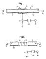
- the fuse arrangement 10 comprises an electrical conductor 12 which provides an electrical connection between a power supply 14 and an electrical load 16.
- a portion 18 of the conductor 12 is stripped of the conductor insulation 20.
- the portion 18 has a composition, shape and size such that the portion has a predetermined melting point.
- a heating element 22 is attached to the portion 18 of the conductor 12.
- the heating element 22 is capable of reaching temperatures in excess of the predetermined melting point.
- a switch 24 is connected between the heating element 22 and electrical ground. The switch 24 is actuated by switch control means 26.
- the switch control means 26 receives signals from one or more sensors 28.
- the switch 24 is normally open and may be a relay operated switch or a semiconductor switch (such as a transistor).
- the sensors 28 monitor predetermined adverse conditions such as high temperature, overload current, and in respect of use on a motor vehicle, a vehicle crash.
- the switch control means 26 is an electronic circuit or microcomputer which receives signals from the sensor or sensors 28. On receipt of any adverse signal from the or one of the sensors 28, the switch control means 26 closes the switch 24. Closure of the switch 24 connects the heating element 22 between the power supply 14 and electrical ground and, as a consequence, heats the heating element. Heating of the heating element 22 causes the portion 18 of the conductor 12 to melt disconnecting the power supply 14 from the electrical loads 16.
- the switch control means 26 is a microcomputer, preferably the microcomputer retains information concerning an adverse condition in a memory in the microcomputer for subsequent interrogation, for example, by a vehicle servicing person.
- the heating element 22 is preferably an annular graphite element which is placed around the portion 18 of the conductor 12.
- the heating element is in the form of a heating coil 30 ( Figure 2) or a substantially flat heating element 32 ( Figure 3) with a heating catalyst 34 between the element and the portion 18 of the conductor 12.
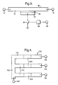
- a further alternative fuse arrangement 100 is shown in Figure 4 for use with electrical conductors 112 in the form of busbars which are connected to the power supply 114 by way of a single busbar 102.
- Each conductor 112 has a heating element 122 (with each heating element being individually operated by a switch and switch control means as described above) attached thereto.
- Such an arrangement provides for selective disconnection of power to one or more of the electrical loads 116.
- the present invention provides for protection of the electrical loads from additional adverse conditions (such as excessive high temperature) besides high or overload current.
- the present invention allows a normal electrical conductor to be used with a portion selected for melting if an adverse condition is detected. Such an arrangement overcomes problems associated with voltage drop across a fuse as no such voltage drop is generated with the present invention.
- the present invention is for use in a motor vehicle and can be used to disconnect the power supply from the vehicle battery in the event of the motor vehicle being involved in a crash.
Landscapes
- Fuses (AREA)
Applications Claiming Priority (2)
| Application Number | Priority Date | Filing Date | Title |
|---|---|---|---|
| GB9726433A GB2332574B (en) | 1997-12-16 | 1997-12-16 | A fuse arrangement |
| GB9726433 | 1997-12-16 |
Publications (2)
| Publication Number | Publication Date |
|---|---|
| EP0924735A2 true EP0924735A2 (fr) | 1999-06-23 |
| EP0924735A3 EP0924735A3 (fr) | 1999-11-03 |
Family
ID=10823604
Family Applications (1)
| Application Number | Title | Priority Date | Filing Date |
|---|---|---|---|
| EP98203980A Withdrawn EP0924735A3 (fr) | 1997-12-16 | 1998-11-25 | Agencement de fusibles |
Country Status (2)
| Country | Link |
|---|---|
| EP (1) | EP0924735A3 (fr) |
| GB (1) | GB2332574B (fr) |
Cited By (4)
| Publication number | Priority date | Publication date | Assignee | Title |
|---|---|---|---|---|
| WO2004001925A1 (fr) * | 2002-06-19 | 2003-12-31 | Tyco Electronics Corporation | Dispositif de protection et de commande de charges multiples |
| DE102006021256A1 (de) * | 2006-04-28 | 2007-11-08 | Danfoss Compressors Gmbh | Motorstartschaltkreis |
| US7777438B2 (en) | 2006-07-19 | 2010-08-17 | Danfoss Compressors Gmbh | Motor start circuit |
| US7777992B2 (en) | 2006-11-07 | 2010-08-17 | Danfoss Compressors Gmbh | Motor start circuit |
Families Citing this family (2)
| Publication number | Priority date | Publication date | Assignee | Title |
|---|---|---|---|---|
| DE10356788A1 (de) * | 2003-12-04 | 2005-07-07 | BSH Bosch und Siemens Hausgeräte GmbH | Sicherungsvorrichtung für eine Heizvorrichtung, Heizvorrichtung und Durchlauferhitzer |
| DE102015217190A1 (de) * | 2015-09-09 | 2017-03-09 | Bayerische Motoren Werke Aktiengesellschaft | Kombinierte Sicherung für ein elektrisches Bordnetz eines elektrisch angetriebenen Fahrzeugs |
Citations (7)
| Publication number | Priority date | Publication date | Assignee | Title |
|---|---|---|---|---|
| US3575681A (en) * | 1969-06-11 | 1971-04-20 | Motorola Inc | Remote fuse destruction device |
| US3764948A (en) * | 1970-08-10 | 1973-10-09 | Micro Devices Corp | Thermal limiter for one or more electrical circuits and method of making the same |
| US3958206A (en) * | 1975-06-12 | 1976-05-18 | General Electric Company | Chemically augmented electrical fuse |
| US4677412A (en) * | 1982-07-28 | 1987-06-30 | Dan Sibalis | Energy supplemented electrical fuse |
| AT383697B (de) * | 1983-09-15 | 1987-08-10 | Wickmann Werke Gmbh | Schutzvorrichtung zum unterbrechen eines stromkreises von elektrischen geraeten, maschinen etc. |
| EP0513405A1 (fr) * | 1991-05-11 | 1992-11-19 | Intermacom A.G. | Méthode et dispositif d'interruption de courant pour appareils et équipements actionnés électriquement |
| WO1996033078A1 (fr) * | 1995-04-19 | 1996-10-24 | Power-Motive B.V. | Cosse de batterie |
Family Cites Families (2)
| Publication number | Priority date | Publication date | Assignee | Title |
|---|---|---|---|---|
| JPH08145388A (ja) * | 1994-11-17 | 1996-06-07 | Matsushita Electric Ind Co Ltd | 面状採暖具 |
| DE19735546A1 (de) * | 1997-08-16 | 1999-02-18 | Daimler Benz Ag | Sicherungselement für elektrische Anlagen |
-
1997
- 1997-12-16 GB GB9726433A patent/GB2332574B/en not_active Expired - Fee Related
-
1998
- 1998-11-25 EP EP98203980A patent/EP0924735A3/fr not_active Withdrawn
Patent Citations (7)
| Publication number | Priority date | Publication date | Assignee | Title |
|---|---|---|---|---|
| US3575681A (en) * | 1969-06-11 | 1971-04-20 | Motorola Inc | Remote fuse destruction device |
| US3764948A (en) * | 1970-08-10 | 1973-10-09 | Micro Devices Corp | Thermal limiter for one or more electrical circuits and method of making the same |
| US3958206A (en) * | 1975-06-12 | 1976-05-18 | General Electric Company | Chemically augmented electrical fuse |
| US4677412A (en) * | 1982-07-28 | 1987-06-30 | Dan Sibalis | Energy supplemented electrical fuse |
| AT383697B (de) * | 1983-09-15 | 1987-08-10 | Wickmann Werke Gmbh | Schutzvorrichtung zum unterbrechen eines stromkreises von elektrischen geraeten, maschinen etc. |
| EP0513405A1 (fr) * | 1991-05-11 | 1992-11-19 | Intermacom A.G. | Méthode et dispositif d'interruption de courant pour appareils et équipements actionnés électriquement |
| WO1996033078A1 (fr) * | 1995-04-19 | 1996-10-24 | Power-Motive B.V. | Cosse de batterie |
Cited By (6)
| Publication number | Priority date | Publication date | Assignee | Title |
|---|---|---|---|---|
| WO2004001925A1 (fr) * | 2002-06-19 | 2003-12-31 | Tyco Electronics Corporation | Dispositif de protection et de commande de charges multiples |
| CN100420116C (zh) * | 2002-06-19 | 2008-09-17 | 泰科电子有限公司 | 多负载保护和控制装置及提供电过载保护的方法 |
| DE102006021256A1 (de) * | 2006-04-28 | 2007-11-08 | Danfoss Compressors Gmbh | Motorstartschaltkreis |
| US7630180B2 (en) | 2006-04-28 | 2009-12-08 | Danfoss Compressors Gmbh | Motor starter circuit |
| US7777438B2 (en) | 2006-07-19 | 2010-08-17 | Danfoss Compressors Gmbh | Motor start circuit |
| US7777992B2 (en) | 2006-11-07 | 2010-08-17 | Danfoss Compressors Gmbh | Motor start circuit |
Also Published As
| Publication number | Publication date |
|---|---|
| EP0924735A3 (fr) | 1999-11-03 |
| GB9726433D0 (en) | 1998-02-11 |
| GB2332574A (en) | 1999-06-23 |
| GB2332574B (en) | 2002-06-12 |
Similar Documents
| Publication | Publication Date | Title |
|---|---|---|
| US7205772B2 (en) | Arc fault detector and method | |
| KR100362771B1 (ko) | 배선하니스의ptc장치 | |
| US7791310B2 (en) | Vehicle electrical system including battery state of charge detection on the positive terminal of the battery | |
| CN107706882B (zh) | 用于机动车的车载电路系统内的电负载的电子熔断器 | |
| US7164272B1 (en) | Modular unit connectable to the battery of a vehicle for monitoring its condition and protecting the electrical system of said vehicle | |
| EP2044491B1 (fr) | Module de commutation a semiconducteur bidirectionnel a faible perte, courant eleve autoprotecteur et procede d'exploitation correspondant | |
| US7161782B2 (en) | Intelligent fuse box for the power distribution system of a vehicle | |
| US6087737A (en) | Battery disconnection system | |
| EP0766362A3 (fr) | Elément de protection et méthode pour protéger un circuit | |
| CN111033937B (zh) | 集成开关装置和包括集成开关装置的用于监测和保护电池的系统 | |
| US6492747B1 (en) | Electric fuse | |
| US20050128661A1 (en) | Method and device for protecting a conductor when an electric arc is produced | |
| EP0924735A2 (fr) | Agencement de fusibles | |
| JP2001511730A (ja) | 電気制御機器に対する回路装置 | |
| EP0931701B1 (fr) | Système de déconnexion d'une batterie | |
| US6325171B1 (en) | Vehicle power supply system | |
| MXPA05007960A (es) | Sistema de interrupcion de circuito optico termico. | |
| EP0778645A2 (fr) | Relais de surcharge avec alimentation contrÔlé par commande | |
| WO1995013621A1 (fr) | Connecteurs pour epissures proteges contre les courts-circuits | |
| EP0896341A1 (fr) | Câble d'énergie électrique pour la prévention d'incendie et de surcharge | |
| JPS592524A (ja) | 回路保護方式 | |
| EP0827884A1 (fr) | Système de protection contre le vol | |
| JP3832030B2 (ja) | 電気回路の保護装置 | |
| JP2024022534A (ja) | 車両の車載電圧網用の遮断スイッチ装置 | |
| JPH08340635A (ja) | 自動車用ワイヤハーネスの電源分配装置 |
Legal Events
| Date | Code | Title | Description |
|---|---|---|---|
| PUAI | Public reference made under article 153(3) epc to a published international application that has entered the european phase |
Free format text: ORIGINAL CODE: 0009012 |
|
| AK | Designated contracting states |
Kind code of ref document: A2 Designated state(s): DE ES FR GB IT |
|
| AX | Request for extension of the european patent |
Free format text: AL;LT;LV;MK;RO;SI |
|
| PUAL | Search report despatched |
Free format text: ORIGINAL CODE: 0009013 |
|
| AK | Designated contracting states |
Kind code of ref document: A3 Designated state(s): AT BE CH CY DE DK ES FI FR GB GR IE IT LI LU MC NL PT SE |
|
| AX | Request for extension of the european patent |
Free format text: AL;LT;LV;MK;RO;SI |
|
| RIC1 | Information provided on ipc code assigned before grant |
Free format text: 6H 01H 85/11 A, 6H 01H 85/46 B |
|
| 17P | Request for examination filed |
Effective date: 20000503 |
|
| AKX | Designation fees paid |
Free format text: DE ES FR GB IT |
|
| STAA | Information on the status of an ep patent application or granted ep patent |
Free format text: STATUS: THE APPLICATION IS DEEMED TO BE WITHDRAWN |
|
| 18D | Application deemed to be withdrawn |
Effective date: 20051119 |