US7205772B2 - Arc fault detector and method - Google Patents
Arc fault detector and method Download PDFInfo
- Publication number
- US7205772B2 US7205772B2 US11/312,929 US31292905A US7205772B2 US 7205772 B2 US7205772 B2 US 7205772B2 US 31292905 A US31292905 A US 31292905A US 7205772 B2 US7205772 B2 US 7205772B2
- Authority
- US
- United States
- Prior art keywords
- signal
- arc
- arc fault
- switch
- voltage
- Prior art date
- Legal status (The legal status is an assumption and is not a legal conclusion. Google has not performed a legal analysis and makes no representation as to the accuracy of the status listed.)
- Expired - Fee Related
Links
- 238000000034 method Methods 0.000 title description 16
- 238000001514 detection method Methods 0.000 claims abstract description 30
- 230000001052 transient effect Effects 0.000 claims abstract description 25
- 230000008859 change Effects 0.000 claims description 33
- 238000001914 filtration Methods 0.000 claims description 4
- 239000004020 conductor Substances 0.000 abstract description 16
- 230000003068 static effect Effects 0.000 abstract description 3
- 230000003139 buffering effect Effects 0.000 abstract 1
- 238000010586 diagram Methods 0.000 description 11
- 239000003990 capacitor Substances 0.000 description 7
- 230000007704 transition Effects 0.000 description 5
- 230000003111 delayed effect Effects 0.000 description 4
- 230000008901 benefit Effects 0.000 description 3
- 238000012544 monitoring process Methods 0.000 description 3
- 230000009286 beneficial effect Effects 0.000 description 2
- 230000001934 delay Effects 0.000 description 2
- 239000000463 material Substances 0.000 description 2
- 230000032683 aging Effects 0.000 description 1
- 230000004075 alteration Effects 0.000 description 1
- 230000008033 biological extinction Effects 0.000 description 1
- 230000000295 complement effect Effects 0.000 description 1
- 238000010276 construction Methods 0.000 description 1
- 230000008878 coupling Effects 0.000 description 1
- 238000010168 coupling process Methods 0.000 description 1
- 238000005859 coupling reaction Methods 0.000 description 1
- 230000006378 damage Effects 0.000 description 1
- 238000001704 evaporation Methods 0.000 description 1
- 239000000446 fuel Substances 0.000 description 1
- 230000001939 inductive effect Effects 0.000 description 1
- 238000009413 insulation Methods 0.000 description 1
- 230000007246 mechanism Effects 0.000 description 1
- 238000002844 melting Methods 0.000 description 1
- 230000008018 melting Effects 0.000 description 1
- 230000004048 modification Effects 0.000 description 1
- 238000012986 modification Methods 0.000 description 1
- 230000002265 prevention Effects 0.000 description 1
- 230000004044 response Effects 0.000 description 1
- 230000000630 rising effect Effects 0.000 description 1
- 238000005070 sampling Methods 0.000 description 1
- 230000009528 severe injury Effects 0.000 description 1
- 239000000725 suspension Substances 0.000 description 1
- 230000002459 sustained effect Effects 0.000 description 1
Images


Classifications
-
- H—ELECTRICITY
- H02—GENERATION; CONVERSION OR DISTRIBUTION OF ELECTRIC POWER
- H02H—EMERGENCY PROTECTIVE CIRCUIT ARRANGEMENTS
- H02H1/00—Details of emergency protective circuit arrangements
- H02H1/0007—Details of emergency protective circuit arrangements concerning the detecting means
- H02H1/0015—Using arc detectors
-
- G—PHYSICS
- G01—MEASURING; TESTING
- G01R—MEASURING ELECTRIC VARIABLES; MEASURING MAGNETIC VARIABLES
- G01R31/00—Arrangements for testing electric properties; Arrangements for locating electric faults; Arrangements for electrical testing characterised by what is being tested not provided for elsewhere
- G01R31/50—Testing of electric apparatus, lines, cables or components for short-circuits, continuity, leakage current or incorrect line connections
- G01R31/52—Testing for short-circuits, leakage current or ground faults
-
- H—ELECTRICITY
- H02—GENERATION; CONVERSION OR DISTRIBUTION OF ELECTRIC POWER
- H02H—EMERGENCY PROTECTIVE CIRCUIT ARRANGEMENTS
- H02H3/00—Emergency protective circuit arrangements for automatic disconnection directly responsive to an undesired change from normal electric working condition with or without subsequent reconnection ; integrated protection
- H02H3/44—Emergency protective circuit arrangements for automatic disconnection directly responsive to an undesired change from normal electric working condition with or without subsequent reconnection ; integrated protection responsive to the rate of change of electrical quantities
Definitions
- the present invention relates generally to the protection of electrical circuits, and, more specifically to the art of electrical arc detection and prevention.
- future vehicle concepts are being studied requiring increased voltage levels in direct current (DC) systems to as high as 42 volts, approximately three times greater than conventional 14 volt systems.
- DC direct current
- the driving forces contributing toward this change are the need to reduce fuel consumption and the introduction of additional electrical features.
- New power networks must accommodate the increased energy demand of comfort and security devices as well as the electrical needs of major systems such as braking, electric power steering and suspension systems.
- Arc faults in parallel to the load are identified as parallel arc faults.
- An example of parallel arc faults can be damaged wires drawing an arc to a ground potential, such as a chassis of an automobile. The insulation jacket of such wires might be broken due to aging or shaved, chaffed or pinched cable jackets.
- This type of arc fault is usually created by a temporary short circuit.
- the arc fault current may thermally over load and damage contacts within the circuit due to low contact force resulting in melting and evaporating contact material followed by more arcing.
- the arc fault current limited by the circuit impedance and the arc voltage, can be significantly lower than the trip current of the protection device such as a fuse or circuit breaker, so that the fault is cleared late depending on the time or current characteristics or in some cases not at all.
- arc detection and protection systems and methods for DC circuits capable of rapidly detecting both parallel and series arcs. It would be beneficial to have a system and method capable of distinguishing unwanted and unplanned arcs from expected transient arcs such as those caused by the opening of a load switch. It would be further beneficial to utilize arc detection components such as sensors that are small so that they can be incorporated in devices such as electrical connectors, junction blocks, relays, circuit breakers, and the like. It would also be desirable to have a systems and methods continuously monitoring for arcing conditions rather than periodically sampling. It would further be desirable to have an arc detection and protection system that uses low cost components without requiring the use of microprocessors or complex algorithms.
- the methods and apparatus of the present invention address many of the shortcomings of the prior art.
- the present invention provides a system and method of detecting an arc fault by detecting a current change indicative of an arc fault.
- An exemplary embodiment of the invention is capable of distinguishing an arc fault from slow current transients caused by load variations and low frequency commutation ripple current of DC motors under normal operating conditions.
- An exemplary embodiment of the invention includes a switch transient detector which detects voltage differential across load switches and generates a switch transient signal which is used to prevent a trip signal from being generated. This eliminates a source for nuisance tripping of a circuit interrupter and helps to avoid the need for costly microprocessors and complex algorithms to distinguish switch transients.
- a current shunt resistor is coupled at the input side of a protected load as part of a system to detect a current change indicative of an arc fault.
- the current shunt resistor is small enough to be deployed in devices such as smart electrical connectors and smart junction blocks.
- a pickup coil wound on a toroidal or UI type magnetic core is coupled at the input side of a protected load to detect a current change indicative of an arc fault. Consequently, the invention is capable of being deployed at only an input side or only a load side without a need for sensors, wires, and other components to be deployed on both a load and input side.
- a first preferred embodiment of an arc fault detector includes a current shunt resistor coupled in series with a circuit and an arc discriminator including an amplifier sensing a first voltage on a first side of the current shunt resistor, sensing a second voltage on a second side of the current shunt resistor, and producing a first signal proportional to a current flow through the current shunt resistor.
- the arc discriminator further includes a change detector receiving the first signal as input and producing an arc fault detection signal as output when the change detector detects a change in the first signal indicative of a presence of an arc fault in the circuit.
- the change detector includes a series arc detector and a parallel arc detector.
- an arc fault detector includes a current monitor detecting a rate of change in electrical current in said circuit and producing a first signal indicative of said rate of change.
- the arc fault detector further includes a signal isolator electrically coupled in series with the circuit monitor filtering the first signal to substantially eliminate signals outside a selected frequency range, the signal isolator producing a filtered signal (i.e., isolating a desired signal) representing changes in the electrical current within the selected frequency range.
- the arc fault detector further includes an arc indicator producing an arc detection signal when a voltage level of the filtered signal exceeds at least one threshold.
- the current monitor is toroidal coil wrapped around a magnetic or UI core and the arc indicator is a Schmitt Trigger.
- a preferred method for detecting an arc fault in a circuit in accordance with present invention includes coupling a current shunt resistor in the circuit, monitoring a voltage differential across the current shunt resistor, detecting a change in the voltage differential, comparing the change to at least one threshold, and generating a signal when the change exceeds the at least one threshold.
- a second preferred method for detecting an arc fault in a circuit in accordance with present invention includes providing a coil wrapped around a toroidal core, passing at least one conductor of the system through the center of the toroidal core, detecting a voltage induced in the coil by a change in current flowing through the at least one conductor, filtering the voltage so as to eliminate signals outside a selected frequency range and to produce a filtered or isolated signal, comparing the filtered (i.e., isolated) signal to at least one threshold; and generating an arc detection signal when said filtered signal exceeds said at least one threshold.
- FIG. 1 is a simplified block diagram of a system incorporating a first exemplary embodiment of an arc fault detector in accordance with the present invention
- FIG. 2 is a circuit diagram of a system incorporating the first exemplary embodiment of an arc fault detector in accordance with the present invention
- FIG. 3 is a circuit diagram illustrating an aspect of a fault detector in accordance with the present invention.
- FIG. 4 is a circuit diagram illustrating another aspect of a fault detector in accordance with the present invention.
- FIG. 5 is a simplified block diagram of a system incorporating a second exemplary embodiment of an arc fault detector in accordance with the present invention
- FIG. 6 is a circuit diagram of a system incorporating the second exemplary embodiment of an arc fault detector in accordance with the present invention.
- FIG. 7 is a simplified fragmentary view illustrating an aspect of the present invention.
- FIG. 8 is a flow diagram of an exemplary method in accordance with the present invention.
- FIG. 9 is a flow diagram of another exemplary method in accordance with the present invention.
- the methods and systems of the present invention provide improved arc fault detection capable of detecting series and parallel arcs in a DC circuit using low cost electronics without a need for microprocessors or sophisticated algorithms.
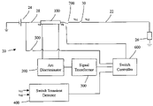
- FIG. 1 is a simplified diagram illustrating a first exemplary embodiment of an arc fault detector 20 of the present invention.
- arc fault detector 20 provides protection to a circuit 22 .
- Circuit 22 includes a direct current power source or battery 24 providing power to a load 26 via a conductor 28 .
- a load switch 30 is disposed in conductor 28 .
- Arc fault detector 20 includes a current shunt resistor 100 , an arc discriminator 200 , an arc fault signal generator or signal transformer 300 , a switch transient detector 400 , a manual switch 500 , a switch controller 600 , and a line interrupter 700 .
- Current shunt resistor 100 is coupled to circuit 22 in series with conductor 28 .
- Arc discriminator 200 detects a voltage differential across current shunt resistor 100 , produces a signal proportional to a current flow through the current shunt resistor 100 , and detects a change in the signal to produce an arc fault detection signal when a series arc fault or parallel arc fault is detected.
- Signal transformer 300 generates a pulse in response to detection of an arc fault.
- the pulse width extends for the period of time that an arc fault is detected.
- Switch transient detector 400 detects a voltage differential across load switch 30 and outputs a pulsed switch transient detection signal when the voltage differential across load switch 30 exceeds a reference value.
- the reference value is set at a level indicating an opening of load switch 30 .
- switch transient detector 400 may include inputs to detect voltage differential across multiple load switches and one or more logic gates to output a switch transient detection signal if a voltage differential across any one of the switches exceeds a reference value.
- Manual switch 500 is used to manually close and open line interrupter 700 .
- Switch controller 600 senses the pulse output from signal transformer 300 , switch transient detection signal from switch transient detector 400 , and voltage provided by battery 24 via manual switch 500 .
- switch controller 600 uses logic gates to output a trip signal controlling line interrupter 700 .
- Circuit 22 includes direct current power source or battery 24 providing power to loads 26 a , 26 b via conductors 28 , 28 a , 28 b .
- a load switch 30 a , 30 b is disposed in each of conductors 28 a , 28 b , respectively.
- Shunt resistor 100 is coupled in series with circuit 22 and also in series with conductor 28 .
- Arc discriminator 200 senses a voltage v a , v b at each side of current shunt resistor 100 .
- arc discriminator 200 includes a current shunt amplifier 202 and change detector 205 .
- Current shunt amplifier 202 senses voltages v a , v b from each side of current shunt resistor 100 at input terminals 3 (+ve) and 4 ( ⁇ ve), respectively. It is assumed that v a is more positive than v b as current flows from v a to v b in current shunt resistor 100 .
- Current shunt amplifier 202 outputs a voltage signal to a change detector 205 . The voltage signal is proportional to the current flowing through current shunt resistor 100 .
- Change detector 205 includes output resistor 204 electrically coupled to a pin 1 of current shunt amplifier 202 .
- Change detector 205 further includes a series arc fault detector 206 and a parallel arc fault detector 208 each feeding an output signal to an OR Gate 210 as further described below.
- Current shunt amplifier 202 is coupled to an input of a first buffer 212 .
- First buffer 212 has a first output electrically coupled to a first delay circuit 213 and a second output electrically coupled to a first reference circuit 215 .
- First delay circuit 213 provides a delayed signal as an output to a first input of a first comparator 224 .
- First reference circuit 215 provides a reference signal as an output to a second input of first comparator 224 .
- Series arc fault detector 206 includes first delay circuit 213 , first reference circuit 215 , and first comparator 224 .
- First delay circuit 213 includes a low pass signal isolator (R-C circuit) 214 including a resistor 216 and a capacitor 218 .
- First delay circuit 213 further includes a second splitter or buffer 220 and a resistor 222 .
- First reference circuit 215 includes a resistor 225 electrically coupled to an input of an amplifier 226 .
- First comparator 224 is configured to output a series arc detection signal only when a voltage at the output of first delay circuit 213 is greater than a voltage at the output of first reference circuit 215 . This condition occurs when there is a decrease in the voltage signal provided by the output of current shunt amplifier 202 which causes the voltage in first reference circuit 215 to decrease.
- the time delay provided by low pass signal isolator 214 delays a decrease in voltage in first delay circuit 213 enabling the voltage in first delay circuit 213 to exceed the voltage in first reference circuit 215 .
- first reference circuit 215 includes amplifier 226 which provides a gain.
- First comparator 224 outputs to a first input of OR Gate 210 .
- OR Gate 210 is configured to output an arc fault detection signal when the said series arc fault detection signal is detected at the first input.
- Parallel arc fault detector 208 includes a second delay circuit 217 which originates from a second output of second buffer 220 , a second reference circuit 219 which originates from the second output of first buffer 212 , and a second comparator 252 .
- Second delay circuit 217 includes a resistor 253 electrically coupled to an input of an amplifier 254 .
- Second reference circuit 219 includes a resistor 250 .
- Second delay circuit 217 provides a delayed signal as an output to a second input of second comparator 252 .
- Second reference circuit 219 provides a reference signal as an output to a first input of second comparator 252 .
- Second comparator 252 is configured to output a parallel arc detection signal only when a voltage at the output of delay circuit 217 is less than a voltage at the output of reference circuit 219 . This condition occurs when there is an increase in the voltage signal provided by the output of current shunt amplifier 202 which causes the voltage in reference circuit 219 to increase.
- the time delay provided by low pass signal isolator 214 delays an increase in voltage in delay circuit 217 enabling the voltage in reference circuit 219 to exceed the voltage in delay circuit 217 .
- delay circuit 217 includes amplifier 254 which provides a gain.
- Second comparator 252 outputs to a second input of OR Gate 210 .
- OR Gate 210 is configured to output an arc fault detection signal when the said parallel arc fault detection signal is detected at the second input.
- the output signal from current shunt differential amplifier 202 is buffered with splitter or buffer 212 and the buffered voltage at a first output 8 is fed to a low pass signal isolator 214 including a resistor 216 and a capacitor 218 to introduce a time delay into the signal and to signal isolator low frequency ripple due to motor loads.
- the output of low pass signal isolator 214 is buffered by buffer 220 and fed to an input resistor 222 electrically coupled to the +ve input 9 of a comparator 224 .
- the amplified signal of buffer 212 is fed to input resistor 225 of buffer 226 electrically coupled to the ⁇ ve 8 input of comparator 224 .
- Comparator 224 compares voltage input at pin 8 with time delayed voltage input at pin 9 to detect a change in voltage that exceeds a gain provided by amplifier 226 .
- the amplifier gain is selected such that comparator 224 does not produce output voltage under normal conditions. In an exemplary embodiment, a gain of 1.1 to 1.2 is selected.
- Second comparator 252 When a parallel arc occurs, the +ve input 5 of second comparator 252 is greater than the ⁇ ve input. 4 . This is because low pass signal isolator 214 filters the voltage due to the initial current transient of the arc. This introduces a time delay. Second comparator 252 outputs a parallel arc detection signal to a second input of OR Gate 210 when a voltage at the output of delay circuit 217 is less than a voltage at the output of reference circuit 219 .
- OR Gate 210 produces an output signal at pin 1 indicating an arc fault which is sensed by signal transformer 300 .
- signal transformer 300 includes Schmitt Trigger 310 and J-K Flip-Flop 312 .
- the output signal from OR Gate 210 is received by input 5 of Schmitt Trigger 310 .
- Schmitt Trigger 310 output at pin 8 is fed to a clock input pin 3 of J-K Flip Flop 312 .
- Under fault J-K Flip Flop 312 is set with the rising edge of the input clock at pin 3 , a complementary output of the Q at pin 2 of J-K Flip Flop 312 goes from High to Low during fault. Under normal conditions pin 2 is High.
- the output signal from pin 2 is fed to an input 11 of an OR Gate 602 included in Switch Controller 600 .
- switch transient detector 400 includes a switch transition detection circuit 402 a , 402 b , 402 c for each switch being monitored.
- switch transition detection circuit 402 a senses a voltage v s1 , v s2 on each side of load switch 30 a .
- the voltages v s1 , v s2 are each fed through a respective signal conditioner 404 , 406 fed to a summing amplifier 408 .
- a voltage differential is output by summing amplifier 408 and fed to a comparator 410 where the differential voltage is compared to a reference voltage with a reference value preferably set between 6 and 10 volts.
- Switch transition circuits 402 b , 402 c are structured and function similar to switch transition circuit 402 a .
- the output of the respective comparators 410 a , 410 b , 410 c associated with each monitored switch 30 a , 30 b , 700 is fed to an OR Gate 412 .
- the voltages differential across each of the switch terminals 30 a , 30 b , 700 and the output of the switch transient detector 400 are Low.
- a switch 30 a , 30 b , 700 opening under load creates an arc across the switch, which causes voltage drop across the switch. Under this condition, the output of switch transient detector 400 goes High.
- the outputs from each of the switch transition detection circuit 402 a , 402 b , 402 c are fed to the input pins 2 , 3 , and 4 of OR Gate 412 .
- the output of OR Gate 412 is fed to an input 10 of Or Gate 602 .
- Manual switch 500 enables line interrupter 700 to be manually reset.
- Manual switch 500 functions to provide a mechanism to manually close and open line interrupter 700 .
- Line interrupter 700 functions to disconnect an arc fault from power source 24 .
- Manual switch 500 is a single pole double throw switch with a first pole grounded.
- a second pole is electrically coupled to a 15V supply derived from power supplied-from 48V battery 24 by using linear regulators 502 a , 502 b .
- Two regulators 502 a , 502 b are cascaded to reduce power dissipation in the individual devices.
- the second pole is electrically coupled to a pin 9 of an AND Gate 604 included in Switch Controller 600 .
- the second pole is also ground through capacitor 504 and resistor 506 .
- output pin 8 of Schmitt Trigger 310 feeds a signal to input pin 3 of Flip Flop 312 thereby setting Flip Flop 312 . Consequently, output pin 2 of Flip Flop 312 goes low which is fed to input pin 11 of OR Gate 602 . Since all of the inputs ( 9 , 10 , 11 , 12 ) of OR Gate 602 are Low, the output at pin 13 is Low. This Low output is fed to input pin 10 of AND Gate 604 . The signal from manual switch 500 is fed to input pin 9 of AND Gate 604 . The output 13 of AND Gate 604 is buffered by buffer 608 and fed to base of transistor 606 to turn OFF. This causes the line interrupter 700 to trip.
- J-K Flip Flop 312 is in a set condition where pin 2 is Low.
- manual switch 500 disconnects the 15V power supply and connects to input pin 1 of Schmitt Trigger 310 via capacitor 504 and an amplifier 508 .
- This pulse is fed to input pin 1 of Schmitt Trigger 310 .
- Output pin 2 is electrically coupled to input pin 3 producing a pulse of finite pulse width at output pin 4 of Schmitt Trigger 310 . This pulse width depends on the R-C time constant of resistor 506 and capacitor 504 .
- the output of pin 4 of Schmitt Trigger 310 is electrically coupled to reset pin 4 of J-K Flip Flop 312 and also to the input pin 9 of OR Gate 602 .
- the J-K Flip Flop 312 resets and thus makes the output pin 2 High, which is electrically coupled to the input pin 11 of OR Gate 602 .
- the output 13 of OR Gate 602 is High and fed to input pin 10 of AND Gate 604 . Since two inputs ( 9 and 10 ) of AND Gate 604 are High it output at pin 13 is High driving the collector of transistor 606 to Low. This Low signal to the input of line interrupter 700 closes line interrupter 700 .
- Line interrupter 700 can be manually opened by connecting manual switch 500 to ground, causing the output 13 of AND Gate 604 to go Low, thus tripping line interrupter 700 .
- Line interrupter 700 can be closed manually by connecting manual switch 500 to 15V power supply.
- FIGS. 5 and 6 illustrate a second exemplary embodiment of an arc fault detector according to the present invention.
- FIG. 5 is a simplified diagram illustrating a second exemplary embodiment of an arc fault detector 1020 of the present invention.
- arc fault detector 1020 provides protection to a circuit 1022 .
- Circuit 1022 includes a direct current power source or battery 1024 providing power to a load 1026 via a conductor 1028 .
- a load switch 1030 is disposed in conductor 1028 .
- Arc fault detector 1020 includes a current monitor 1100 detecting a rate of change in electrical current in circuit 1022 and producing a first signal indicative of said rate of change.
- Arc fault detector 1020 further includes a signal isolator 1110 electrically coupled in series with the current monitor 1100 .
- the signal isolator functioning to signal isolator the first signal to substantially eliminate signals outside a selected frequency range, the signal isolator 1110 producing a filtered signal representing changes in the electrical current within the selected frequency range.
- Arc fault detector 1020 also includes an arc indicator (preferably Schmitt Trigger 310 ) producing an arc detection signal when a voltage level of the filtered signal exceeds at least one threshold.
- the threshold is preferably established by Schmitt Trigger 310 .
- Another device such as amplifier 1108 , or a comparator may also be used to provide a threshold.
- Another device such as a monostable vibrator may also be used
- Arc fault detector 1020 includes current monitor 1100 and an arc determining circuit 290 .
- Current monitor 1100 includes a coil 1101 wrapped around a toroidal core or UI core 1102 .
- Arc determining circuit 290 includes an attenuator or first resistor 1103 , a second resistor 1104 , a zener diode 1106 , an operational amplifier 1108 , and a low pass signal isolator 1110 .
- Low pass signal isolator 1110 includes a resistor 1112 and a capacitor 1114 .
- Arc fault detector 1020 further includes a signal transformer 300 , a switch transient detector 400 , a manual switch 500 , a switch controller 600 , and a line interrupter 700 .
- Circuit 1022 passes through the center of toroidal core 1102 inducing a voltage pulse in coil 1101 due to a current change caused by a series or parallel arc fault.
- Attenuator or resistor 1103 is selected so that the voltage level of the filtered signal output to Schmitt Trigger 310 when generated by operation of a motor commutator is lower than the threshold voltage needed to be provided to Schmitt Trigger 310 to enable an output pulse to be generated.
- Resistor 1104 provides a path to ground for the voltage pulse.
- the voltage is provided to operational amplifier 1108 via zener diode 1106 which clamps the voltage to 12V to protect downstream components in the event the induced voltage is too high.
- Signal transformer 300 , switch transient detector 400 , manual switch 500 , switch controller 600 , and line interrupter 700 of arc fault detector 1020 are configured and operate as described in the exemplary embodiment of arc fault detector 20 above.
- FIG. 7 is a fragmentary simplified diagram illustrating how coil 1501 wrapped around a toroidal core 1502 is used as part of an arc fault detector 1520 protecting a zone 1600 .
- arc fault detector 1520 provides protection to a circuit 1522 and zone 1600 .
- Circuit 1522 includes a direct current power source or battery 1524 providing power to loads 1526 a , 1526 b via respective conductors 1528 a , 1528 b .
- a line interrupter 700 is disposed in circuit 1522 . Both conductors 1528 a , 1528 b pass through the center of toroidal core 1502 . When a current changes due to arc fault in either conductor 1528 a , 1528 b , a voltage is induced in coil 1501 .
- An arc determining circuit, signal transformer, switch transient detector, manual switch, switch controller, and line interrupter 700 may be incorporated in arc fault detector 1520 as described above.
- a first preferred method 2000 for detecting an arc fault in a circuit in accordance with present invention includes providing a shunt resistor in the circuit 2002 , monitoring a voltage differential across the shunt resistor 2004 , detecting a change in the voltage differential 2006 , comparing the change to at least one threshold 2008 , and generating a signal when the change exceeds the at least one threshold 2010 .
- a second preferred method 3000 of detecting an arc fault in a system includes providing a coil wrapped around a toroidal core 3002 ; passing at least one conductor of the system through the center of the toroidal core 3004 ; detecting a voltage induced in the coil by a change in current flowing through the at least one conductor 3006 ; comparing the voltage to at least one threshold 3008 ; and generating a signal when the voltage exceeds the at least one threshold 3010 .
- line interrupter 700 is preferably embodied as a static relay.
- Line interrupter 700 may also be an electromechanical switch, a thyristor, an intelligent switch, or the like.
- Schmitt Trigger 310 and J-K Flip Flop 312 may be replaced by other devices that provide pulsed signals known to those skilled in the art such as monostable multivibrators, bistable multivibrators, timers, latches, or the like.
Landscapes
- Physics & Mathematics (AREA)
- General Physics & Mathematics (AREA)
- Emergency Protection Circuit Devices (AREA)
Abstract
An arc fault detector includes a shunt resistor deployed in a protected circuit, an arc discriminator sensing voltages across the shunt resistor and producing an arc indication deduced from current variations associated with parallel and series arc faults, a signal transformer buffering the arc detection signal and producing a pulse, a switch transient detector sensing a voltage differential across load switches and producing a pulsed switch transient signal when the voltage differential across load switches exceeds a reference value, a line interrupter, such as a static relay, a switch controller including logic gates generating a trip signal based on predetermined criteria, and a manual switch for resetting the line interrupter. An embodiment comprises a voltage sensing coil enveloping a toroidal core to detect current variations in conductors passing through the core.
Description
This application is a continuation of, and claims benefit of priority from, co-pending U.S. non-provisional patent application Ser. No. 10/831,733, which was filed Apr. 23, 2004 now U.S. Pat. No. 7,009,406, and which is hereby incorporated by reference. This application also claims benefit of priority from U.S. provisional patent application Ser. No. 60/465,461, filed Apr. 24, 2003, which is also hereby incorporated by reference.
The present invention relates generally to the protection of electrical circuits, and, more specifically to the art of electrical arc detection and prevention.
A need exists within the automotive industry to increase the electrical power capability for future vehicles. For example, future vehicle concepts are being studied requiring increased voltage levels in direct current (DC) systems to as high as 42 volts, approximately three times greater than conventional 14 volt systems. The driving forces contributing toward this change are the need to reduce fuel consumption and the introduction of additional electrical features. New power networks must accommodate the increased energy demand of comfort and security devices as well as the electrical needs of major systems such as braking, electric power steering and suspension systems.
The introduction of a system voltage higher than approximately 20 volts causes considerable component and system changes and has the potential to significantly impact system reliability and safety. For example, one significant impact of the increase in system voltage to levels such as the envisioned forty-two volt, direct-current network is the need to address the increased potential for arcing (shorting over a finite gap) from and within the electrical distribution systems and components. One particularly vulnerable component of electrical systems are the wiring harnesses, wherein arc faults may be encountered as a result of cut, pinched or chaffed wiring. Accordingly, a substantial need exists to protect electrical distribution systems, and particularly wire harnesses, from unwanted arc faults.
In the instance of a wire being cut or broken under an electrical load, an arc may be drawn between both ends. Such an arc is unwanted and unplanned for, and its extinction is uncertain. Therefore, severe damage may occur if the arc is sustained. This type of arc fault is called a series arc fault, as the arc is in series to the load. Hot unplugs due to vibrating loose connections fall into the same series arc fault category. Series arc faults cannot typically be cleared by fuses or circuit breakers.
Arc faults in parallel to the load are identified as parallel arc faults. An example of parallel arc faults can be damaged wires drawing an arc to a ground potential, such as a chassis of an automobile. The insulation jacket of such wires might be broken due to aging or shaved, chaffed or pinched cable jackets. This type of arc fault is usually created by a temporary short circuit. The arc fault current, however, may thermally over load and damage contacts within the circuit due to low contact force resulting in melting and evaporating contact material followed by more arcing. The arc fault current, limited by the circuit impedance and the arc voltage, can be significantly lower than the trip current of the protection device such as a fuse or circuit breaker, so that the fault is cleared late depending on the time or current characteristics or in some cases not at all.
Many patents disclose arc fault detection systems and methods for alternating current (AC) applications. However, fewer arc detection devices and methods are disclosed for direct current (DC) applications.
Consequently, there remains a need in the art for arc detection and protection systems and methods for DC circuits capable of rapidly detecting both parallel and series arcs. It would be beneficial to have a system and method capable of distinguishing unwanted and unplanned arcs from expected transient arcs such as those caused by the opening of a load switch. It would be further beneficial to utilize arc detection components such as sensors that are small so that they can be incorporated in devices such as electrical connectors, junction blocks, relays, circuit breakers, and the like. It would also be desirable to have a systems and methods continuously monitoring for arcing conditions rather than periodically sampling. It would further be desirable to have an arc detection and protection system that uses low cost components without requiring the use of microprocessors or complex algorithms.
The methods and apparatus of the present invention address many of the shortcomings of the prior art. The present invention provides a system and method of detecting an arc fault by detecting a current change indicative of an arc fault. An exemplary embodiment of the invention is capable of distinguishing an arc fault from slow current transients caused by load variations and low frequency commutation ripple current of DC motors under normal operating conditions. An exemplary embodiment of the invention includes a switch transient detector which detects voltage differential across load switches and generates a switch transient signal which is used to prevent a trip signal from being generated. This eliminates a source for nuisance tripping of a circuit interrupter and helps to avoid the need for costly microprocessors and complex algorithms to distinguish switch transients.
In an exemplary embodiment, a current shunt resistor is coupled at the input side of a protected load as part of a system to detect a current change indicative of an arc fault. In an exemplary embodiment, the current shunt resistor is small enough to be deployed in devices such as smart electrical connectors and smart junction blocks.
In another exemplary embodiment, a pickup coil wound on a toroidal or UI type magnetic core is coupled at the input side of a protected load to detect a current change indicative of an arc fault. Consequently, the invention is capable of being deployed at only an input side or only a load side without a need for sensors, wires, and other components to be deployed on both a load and input side.
A first preferred embodiment of an arc fault detector according to the present invention includes a current shunt resistor coupled in series with a circuit and an arc discriminator including an amplifier sensing a first voltage on a first side of the current shunt resistor, sensing a second voltage on a second side of the current shunt resistor, and producing a first signal proportional to a current flow through the current shunt resistor. The arc discriminator further includes a change detector receiving the first signal as input and producing an arc fault detection signal as output when the change detector detects a change in the first signal indicative of a presence of an arc fault in the circuit.
In a preferred embodiment the change detector includes a series arc detector and a parallel arc detector.
Another preferred embodiment of an arc fault detector according to the present invention includes a current monitor detecting a rate of change in electrical current in said circuit and producing a first signal indicative of said rate of change. The arc fault detector further includes a signal isolator electrically coupled in series with the circuit monitor filtering the first signal to substantially eliminate signals outside a selected frequency range, the signal isolator producing a filtered signal (i.e., isolating a desired signal) representing changes in the electrical current within the selected frequency range. The arc fault detector further includes an arc indicator producing an arc detection signal when a voltage level of the filtered signal exceeds at least one threshold.
In an exemplary embodiment, the current monitor is toroidal coil wrapped around a magnetic or UI core and the arc indicator is a Schmitt Trigger.
A preferred method for detecting an arc fault in a circuit in accordance with present invention includes coupling a current shunt resistor in the circuit, monitoring a voltage differential across the current shunt resistor, detecting a change in the voltage differential, comparing the change to at least one threshold, and generating a signal when the change exceeds the at least one threshold.
A second preferred method for detecting an arc fault in a circuit in accordance with present invention includes providing a coil wrapped around a toroidal core, passing at least one conductor of the system through the center of the toroidal core, detecting a voltage induced in the coil by a change in current flowing through the at least one conductor, filtering the voltage so as to eliminate signals outside a selected frequency range and to produce a filtered or isolated signal, comparing the filtered (i.e., isolated) signal to at least one threshold; and generating an arc detection signal when said filtered signal exceeds said at least one threshold.
These and other features and advantages of the present invention will become apparent from the following brief description of the drawings, detailed description, and appended drawings.
The above-mentioned features of the present invention can be more clearly understood from the following detailed description considered in conjunction with the following drawings, in which like numerals represent like elements and in which:
As discussed above, the methods and systems of the present invention provide improved arc fault detection capable of detecting series and parallel arcs in a DC circuit using low cost electronics without a need for microprocessors or sophisticated algorithms.
Referring first to FIGS. 1–4 , FIG. 1 is a simplified diagram illustrating a first exemplary embodiment of an arc fault detector 20 of the present invention. As shown in FIG. 1 , arc fault detector 20 provides protection to a circuit 22. Circuit 22 includes a direct current power source or battery 24 providing power to a load 26 via a conductor 28. A load switch 30 is disposed in conductor 28.
Switch transient detector 400 detects a voltage differential across load switch 30 and outputs a pulsed switch transient detection signal when the voltage differential across load switch 30 exceeds a reference value. The reference value is set at a level indicating an opening of load switch 30. As later described, switch transient detector 400 may include inputs to detect voltage differential across multiple load switches and one or more logic gates to output a switch transient detection signal if a voltage differential across any one of the switches exceeds a reference value.
Referring now to FIG. 2 , arc fault detector 20 provides protection to a circuit 22. Circuit 22 includes direct current power source or battery 24 providing power to loads 26 a, 26 b via conductors 28, 28 a, 28 b. A load switch 30 a, 30 b is disposed in each of conductors 28 a, 28 b, respectively.
As shown in FIG. 3 , arc discriminator 200 includes a current shunt amplifier 202 and change detector 205. Current shunt amplifier 202 senses voltages va, vb from each side of current shunt resistor 100 at input terminals 3 (+ve) and 4 (−ve), respectively. It is assumed that va is more positive than vb as current flows from va to vb in current shunt resistor 100. Current shunt amplifier 202 outputs a voltage signal to a change detector 205. The voltage signal is proportional to the current flowing through current shunt resistor 100. Change detector 205 includes output resistor 204 electrically coupled to a pin 1 of current shunt amplifier 202. Change detector 205 further includes a series arc fault detector 206 and a parallel arc fault detector 208 each feeding an output signal to an OR Gate 210 as further described below.
Parallel arc fault detector 208 includes a second delay circuit 217 which originates from a second output of second buffer 220, a second reference circuit 219 which originates from the second output of first buffer 212, and a second comparator 252.
In a series arc condition the current flowing through current shunt resistor 100 goes down compared to a normal condition. The output signal from current shunt differential amplifier 202 is buffered with splitter or buffer 212 and the buffered voltage at a first output 8 is fed to a low pass signal isolator 214 including a resistor 216 and a capacitor 218 to introduce a time delay into the signal and to signal isolator low frequency ripple due to motor loads. The output of low pass signal isolator 214 is buffered by buffer 220 and fed to an input resistor 222 electrically coupled to the +ve input 9 of a comparator 224. The amplified signal of buffer 212 is fed to input resistor 225 of buffer 226 electrically coupled to the −ve 8 input of comparator 224. Comparator 224 compares voltage input at pin 8 with time delayed voltage input at pin 9 to detect a change in voltage that exceeds a gain provided by amplifier 226. The amplifier gain is selected such that comparator 224 does not produce output voltage under normal conditions. In an exemplary embodiment, a gain of 1.1 to 1.2 is selected.
When a series arc occurs, the current suddenly drops initially and current shunt amplifier 202 produces a voltage proportional to the arc current at location “A” and also at location “B”. The magnitudes of the voltages at these points are less than the voltages under normal load before an arc fault. Low pass signal isolator 214 filters the voltage transient caused by the arc current momentary and the buffered output voltage at location “C” is the same as before the arc fault which is greater than the voltage at location “B”. This condition allows comparator 224 to produce output voltage which is fed to input 2 of OR Gate 210.
In the case of a parallel arc fault condition, the current flowing through current shunt resistor 100 goes up compared to a normal load condition. The buffered output of current shunt amplifier 202 at location “A” is electrically coupled to input resistor 250 electrically coupled to the +ve input 5 of a comparator 252. The buffered and time delayed signal isolator output at location “C” is fed to amplifier 254 to produce output at location “D” which is slightly less than at location “A”. This signal is fed to input resistor 256 electrically coupled to the −ve input 4 of comparator 252. Under normal load conditions or under series arc fault condition comparator 252 does not produce an output voltage. When a parallel arc occurs, the +ve input 5 of second comparator 252 is greater than the −ve input. 4. This is because low pass signal isolator 214 filters the voltage due to the initial current transient of the arc. This introduces a time delay. Second comparator 252 outputs a parallel arc detection signal to a second input of OR Gate 210 when a voltage at the output of delay circuit 217 is less than a voltage at the output of reference circuit 219.
When either a series or parallel arc occurs, OR Gate 210 produces an output signal at pin 1 indicating an arc fault which is sensed by signal transformer 300. Referring back to FIG. 2 , signal transformer 300 includes Schmitt Trigger 310 and J-K Flip-Flop 312. The output signal from OR Gate 210 is received by input 5 of Schmitt Trigger 310. Schmitt Trigger 310 output at pin 8 is fed to a clock input pin 3 of J-K Flip Flop 312. Under fault J-K Flip Flop 312 is set with the rising edge of the input clock at pin 3, a complementary output of the Q at pin 2 of J-K Flip Flop 312 goes from High to Low during fault. Under normal conditions pin 2 is High. The output signal from pin 2 is fed to an input 11 of an OR Gate 602 included in Switch Controller 600.
Referring to FIGS. 2 and 4 , switch transient detector 400 includes a switch transition detection circuit 402 a, 402 b, 402 c for each switch being monitored. As shown on FIG. 4 , switch transition detection circuit 402 a senses a voltage vs1, vs2 on each side of load switch 30 a. The voltages vs1, vs2 are each fed through a respective signal conditioner 404, 406 fed to a summing amplifier 408. A voltage differential is output by summing amplifier 408 and fed to a comparator 410 where the differential voltage is compared to a reference voltage with a reference value preferably set between 6 and 10 volts. Switch transition circuits 402 b, 402 c are structured and function similar to switch transition circuit 402 a. The output of the respective comparators 410 a, 410 b, 410 c associated with each monitored switch 30 a, 30 b, 700 is fed to an OR Gate 412. Under normal conditions, the voltages differential across each of the switch terminals 30 a, 30 b, 700 and the output of the switch transient detector 400 are Low. A switch 30 a, 30 b, 700 opening under load creates an arc across the switch, which causes voltage drop across the switch. Under this condition, the output of switch transient detector 400 goes High. The outputs from each of the switch transition detection circuit 402 a, 402 b, 402 c are fed to the input pins 2, 3, and 4 of OR Gate 412. The output of OR Gate 412 is fed to an input 10 of Or Gate 602.
Under an arc fault condition, output pin 8 of Schmitt Trigger 310 feeds a signal to input pin 3 of Flip Flop 312 thereby setting Flip Flop 312. Consequently, output pin 2 of Flip Flop 312 goes low which is fed to input pin 11 of OR Gate 602. Since all of the inputs (9, 10, 11, 12) of OR Gate 602 are Low, the output at pin 13 is Low. This Low output is fed to input pin 10 of AND Gate 604. The signal from manual switch 500 is fed to input pin 9 of AND Gate 604. The output 13 of AND Gate 604 is buffered by buffer 608 and fed to base of transistor 606 to turn OFF. This causes the line interrupter 700 to trip.
Once line interrupter 700 trips, J-K Flip Flop 312 is in a set condition where pin 2 is Low. By opening and closing, manual switch 500 disconnects the 15V power supply and connects to input pin 1 of Schmitt Trigger 310 via capacitor 504 and an amplifier 508. This produces a voltage spike across resistor 506 since R-C (resistor 506-capacitor 504) combination acts as a differentiator. This pulse is fed to input pin 1 of Schmitt Trigger 310. Output pin 2 is electrically coupled to input pin 3 producing a pulse of finite pulse width at output pin 4 of Schmitt Trigger 310. This pulse width depends on the R-C time constant of resistor 506 and capacitor 504. The output of pin 4 of Schmitt Trigger 310 is electrically coupled to reset pin 4 of J-K Flip Flop 312 and also to the input pin 9 of OR Gate 602. The J-K Flip Flop 312 resets and thus makes the output pin 2 High, which is electrically coupled to the input pin 11 of OR Gate 602. The output 13 of OR Gate 602 is High and fed to input pin 10 of AND Gate 604. Since two inputs (9 and 10) of AND Gate 604 are High it output at pin 13 is High driving the collector of transistor 606 to Low. This Low signal to the input of line interrupter 700 closes line interrupter 700. Line interrupter 700 can be manually opened by connecting manual switch 500 to ground, causing the output 13 of AND Gate 604 to go Low, thus tripping line interrupter 700. Line interrupter 700 can be closed manually by connecting manual switch 500 to 15V power supply.
Referring now to FIGS. 5–6 , FIGS. 5 and 6 illustrate a second exemplary embodiment of an arc fault detector according to the present invention.
As shown on FIG. 7 , arc fault detector 1520 provides protection to a circuit 1522 and zone 1600. Circuit 1522 includes a direct current power source or battery 1524 providing power to loads 1526 a, 1526 b via respective conductors 1528 a, 1528 b. A line interrupter 700 is disposed in circuit 1522. Both conductors 1528 a, 1528 b pass through the center of toroidal core 1502. When a current changes due to arc fault in either conductor 1528 a, 1528 b, a voltage is induced in coil 1501. An arc determining circuit, signal transformer, switch transient detector, manual switch, switch controller, and line interrupter 700 may be incorporated in arc fault detector 1520 as described above.
As shown on FIG. 8 , a first preferred method 2000 for detecting an arc fault in a circuit in accordance with present invention includes providing a shunt resistor in the circuit 2002, monitoring a voltage differential across the shunt resistor 2004, detecting a change in the voltage differential 2006, comparing the change to at least one threshold 2008, and generating a signal when the change exceeds the at least one threshold 2010.
As shown on FIG. 9 , a second preferred method 3000 of detecting an arc fault in a system includes providing a coil wrapped around a toroidal core 3002; passing at least one conductor of the system through the center of the toroidal core 3004; detecting a voltage induced in the coil by a change in current flowing through the at least one conductor 3006; comparing the voltage to at least one threshold 3008; and generating a signal when the voltage exceeds the at least one threshold 3010.
The preferred embodiments shown and described herein are provided merely by way of example and are not intended to limit the scope of the invention in any way. Preferred dimensions, ratios, materials and construction techniques are illustrative only and are not necessarily required to practice the invention. It is intended that the scope of the present invention herein disclosed should not be limited by the particular disclosed embodiments herein. Further modifications and alterations may occur to others upon reading and understanding the specification.
For example, in an exemplary embodiment, line interrupter 700 is preferably embodied as a static relay. Line interrupter 700 may also be an electromechanical switch, a thyristor, an intelligent switch, or the like. Schmitt Trigger 310 and J-K Flip Flop 312 may be replaced by other devices that provide pulsed signals known to those skilled in the art such as monostable multivibrators, bistable multivibrators, timers, latches, or the like.
Claims (11)
1. An arc fault detector for a circuit comprising:
a current monitor detecting a rate of change in electrical current in said circuit and producing a first signal indicative of said rate of change;
a signal isolator electrically coupled in series with said current monitor, said isolator filtering said first signal to substantially eliminate signals outside a selected frequency range, said signal isolator producing a filtered signal representing changes in said electrical current within said selected frequency range;
an arc indicator producing an arc detection signal when a level of said filtered signal exceeds at least one threshold; and
a switch transient detector detecting an arc condition caused by an opening of a switch under load, said switch transient detector detecting a voltage differential across said switch and providing a switch transient signal when said voltage differential exceeds a reference value.
2. The arc fault detector of claim 1 wherein the voltage of said filtered signal is indicative of a magnitude of change in said electrical current in said circuit.
3. The arc fault detector as recited in claim 1 wherein said current monitor comprises a coil and a toroidal core.
4. The arc fault detector as recited in claim 1 wherein said arc indicator comprises an amplifier.
5. The arc fault detector as recited in claim 3 further comprising:
an attenuator electrically coupled in series with said current monitor and said filter, said attenuator attenuating at least one of said first signal and said filtered signal, said attenuator comprising a resistor selected so that said voltage level of said filtered signal, when generated by operation of a motor commutator, is lower than said at least one threshold.
6. The arc fault detector as recited in claim 1 further comprising:
a switch controller sensing said arc detection signal and switch transient signal and producing a trip signal, said switch controller being configured such that it is inhibited from producing a trip signal when it detects a switch transient signal.
7. An arc fault detector for a circuit comprising:
a current monitor detecting a rate of change in electrical current in said circuit and producing a first signal indicative of said rate of change;
a signal isolator electrically coupled in series with said current monitor, said isolator filtering said first signal to substantially eliminate signals outside a selected frequency range, said signal isolator producing a filtered signal representing changes in said electrical current within said selected frequency range; and
an arc indicator producing an arc detection signal when a level of said filtered signal exceeds at least one threshold;
wherein said current monitor comprises a coil and a toroidal core further comprising:
an attenuator electrically coupled in series with said current monitor and said filter, said attenuator attenuating at least one of said first signal and said filtered signal, said attenuator comprising a resistor selected so that said voltage level of said filtered signal, when generated by operation of a motor commutator, is lower than said at least one threshold;
wherein said arc indicator comprises a Schmitt Trigger.
8. The arc fault detector of claim 7 wherein the voltage of said filtered signal is indicative of a magnitude of change in said electrical current in said circuit.
9. The arc fault detector as recited in claim 7 wherein said current monitor comprises a coil and a toroidal core.
10. The arc fault detector as recited in claim 9 further comprising:
an attenuator electrically coupled in series with said current monitor and said filter, said attenuator attenuating at least one of said first signal and said filtered signal, said attenuator comprising a resistor selected so that said voltage level of said filtered signal, when generated by operation of a motor commutator, is lower than said at least one threshold.
11. The arc fault detector as recited in claim 7 wherein said arc indicator comprises an amplifier.
Priority Applications (1)
| Application Number | Priority Date | Filing Date | Title |
|---|---|---|---|
| US11/312,929 US7205772B2 (en) | 2003-04-24 | 2005-12-20 | Arc fault detector and method |
Applications Claiming Priority (3)
| Application Number | Priority Date | Filing Date | Title |
|---|---|---|---|
| US46506103P | 2003-04-24 | 2003-04-24 | |
| US10/831,733 US7009406B2 (en) | 2003-04-24 | 2004-04-23 | Arc fault detector and method |
| US11/312,929 US7205772B2 (en) | 2003-04-24 | 2005-12-20 | Arc fault detector and method |
Related Parent Applications (1)
| Application Number | Title | Priority Date | Filing Date |
|---|---|---|---|
| US10/831,733 Continuation US7009406B2 (en) | 2003-04-24 | 2004-04-23 | Arc fault detector and method |
Publications (2)
| Publication Number | Publication Date |
|---|---|
| US20060214670A1 US20060214670A1 (en) | 2006-09-28 |
| US7205772B2 true US7205772B2 (en) | 2007-04-17 |
Family
ID=33544163
Family Applications (2)
| Application Number | Title | Priority Date | Filing Date |
|---|---|---|---|
| US10/831,733 Expired - Fee Related US7009406B2 (en) | 2003-04-24 | 2004-04-23 | Arc fault detector and method |
| US11/312,929 Expired - Fee Related US7205772B2 (en) | 2003-04-24 | 2005-12-20 | Arc fault detector and method |
Family Applications Before (1)
| Application Number | Title | Priority Date | Filing Date |
|---|---|---|---|
| US10/831,733 Expired - Fee Related US7009406B2 (en) | 2003-04-24 | 2004-04-23 | Arc fault detector and method |
Country Status (1)
| Country | Link |
|---|---|
| US (2) | US7009406B2 (en) |
Cited By (12)
| Publication number | Priority date | Publication date | Assignee | Title |
|---|---|---|---|---|
| US20090059449A1 (en) * | 2006-12-28 | 2009-03-05 | General Electric Company | Series arc fault current interrupters and methods |
| US20090171603A1 (en) * | 2007-12-28 | 2009-07-02 | Sriram Changali | Methods of detecting series arcs in electrical signals |
| US20100020451A1 (en) * | 2008-07-24 | 2010-01-28 | General Electric Company | Arc detection using discrete wavelet transforms |
| US20100165521A1 (en) * | 2008-12-29 | 2010-07-01 | Sriram Changali | Parallel arc detection using discrete wavelet transforms |
| US20110068634A1 (en) * | 2009-09-18 | 2011-03-24 | Power Distribution Inc. | Direct current power supply for mission critical applications |
| WO2011126460A1 (en) | 2010-04-07 | 2011-10-13 | Eti Elektroelement D.D. | Arc preventing switch |
| US8159793B2 (en) | 2008-12-22 | 2012-04-17 | General Electric Company | Arc detection using detailed and approximate coefficients from discrete wavelet transforms |
| US20120319693A1 (en) * | 2010-03-04 | 2012-12-20 | Mitsubishi Electric Corporation | Electric power storage system |
| CN105334425A (en) * | 2014-06-13 | 2016-02-17 | 益而益(集团)有限公司 | Arc fault detection apparatus |
| WO2024111702A1 (en) * | 2022-11-21 | 2024-05-30 | 이성호 | Arc detection system |
| US12081011B2 (en) | 2017-05-23 | 2024-09-03 | Pass & Seymour, Inc. | Arc fault circuit interrupter |
| US12241925B2 (en) | 2019-12-27 | 2025-03-04 | Eaton Intelligent Power Limited | Arc fault detection modules for vehicle electrical systems |
Families Citing this family (108)
| Publication number | Priority date | Publication date | Assignee | Title |
|---|---|---|---|---|
| US7003435B2 (en) * | 2002-10-03 | 2006-02-21 | Leviton Manufacturing Co., Inc. | Arc fault detector with circuit interrupter |
| WO2005027591A1 (en) * | 2003-09-12 | 2005-03-24 | Koninklijke Philips Electronics, N.V. | Ballast with lampholder arc protection |
| US6972572B2 (en) * | 2003-12-22 | 2005-12-06 | Leviton Manufacturing Co., Inc. | Arc fault detector |
| US11881814B2 (en) | 2005-12-05 | 2024-01-23 | Solaredge Technologies Ltd. | Testing of a photovoltaic panel |
| US10693415B2 (en) | 2007-12-05 | 2020-06-23 | Solaredge Technologies Ltd. | Testing of a photovoltaic panel |
| US7443644B2 (en) * | 2006-02-09 | 2008-10-28 | Sam Kyoung Sung | Circuit for preventing malfunction of arc fault detection device |
| JP4875390B2 (en) * | 2006-03-27 | 2012-02-15 | 株式会社ダイヘン | Constriction detection control method for consumable electrode arc welding |
| US7307429B1 (en) * | 2006-07-19 | 2007-12-11 | Eaton Corporation | Apparatus for testing an arc fault circuit interrupter |
| US7489138B2 (en) * | 2006-11-30 | 2009-02-10 | Honeywell International Inc. | Differential arc fault detection |
| DE102006056852A1 (en) * | 2006-12-01 | 2008-06-05 | Robert Bosch Gmbh | detector circuit |
| US8816535B2 (en) | 2007-10-10 | 2014-08-26 | Solaredge Technologies, Ltd. | System and method for protection during inverter shutdown in distributed power installations |
| US8384243B2 (en) | 2007-12-04 | 2013-02-26 | Solaredge Technologies Ltd. | Distributed power harvesting systems using DC power sources |
| US11855231B2 (en) | 2006-12-06 | 2023-12-26 | Solaredge Technologies Ltd. | Distributed power harvesting systems using DC power sources |
| US9130401B2 (en) | 2006-12-06 | 2015-09-08 | Solaredge Technologies Ltd. | Distributed power harvesting systems using DC power sources |
| US11888387B2 (en) | 2006-12-06 | 2024-01-30 | Solaredge Technologies Ltd. | Safety mechanisms, wake up and shutdown methods in distributed power installations |
| US8947194B2 (en) | 2009-05-26 | 2015-02-03 | Solaredge Technologies Ltd. | Theft detection and prevention in a power generation system |
| US11296650B2 (en) | 2006-12-06 | 2022-04-05 | Solaredge Technologies Ltd. | System and method for protection during inverter shutdown in distributed power installations |
| US9088178B2 (en) | 2006-12-06 | 2015-07-21 | Solaredge Technologies Ltd | Distributed power harvesting systems using DC power sources |
| US8963369B2 (en) | 2007-12-04 | 2015-02-24 | Solaredge Technologies Ltd. | Distributed power harvesting systems using DC power sources |
| US8473250B2 (en) | 2006-12-06 | 2013-06-25 | Solaredge, Ltd. | Monitoring of distributed power harvesting systems using DC power sources |
| US8319471B2 (en) | 2006-12-06 | 2012-11-27 | Solaredge, Ltd. | Battery power delivery module |
| US8319483B2 (en) | 2007-08-06 | 2012-11-27 | Solaredge Technologies Ltd. | Digital average input current control in power converter |
| US9112379B2 (en) | 2006-12-06 | 2015-08-18 | Solaredge Technologies Ltd. | Pairing of components in a direct current distributed power generation system |
| US8618692B2 (en) | 2007-12-04 | 2013-12-31 | Solaredge Technologies Ltd. | Distributed power system using direct current power sources |
| US11309832B2 (en) | 2006-12-06 | 2022-04-19 | Solaredge Technologies Ltd. | Distributed power harvesting systems using DC power sources |
| US8013472B2 (en) | 2006-12-06 | 2011-09-06 | Solaredge, Ltd. | Method for distributed power harvesting using DC power sources |
| US12316274B2 (en) | 2006-12-06 | 2025-05-27 | Solaredge Technologies Ltd. | Pairing of components in a direct current distributed power generation system |
| US11735910B2 (en) | 2006-12-06 | 2023-08-22 | Solaredge Technologies Ltd. | Distributed power system using direct current power sources |
| US11687112B2 (en) | 2006-12-06 | 2023-06-27 | Solaredge Technologies Ltd. | Distributed power harvesting systems using DC power sources |
| US11569659B2 (en) | 2006-12-06 | 2023-01-31 | Solaredge Technologies Ltd. | Distributed power harvesting systems using DC power sources |
| US8344556B2 (en) * | 2007-10-30 | 2013-01-01 | Sta-Rite Industries, Llc | Foam proportioning system with solid state contactor |
| US8049523B2 (en) | 2007-12-05 | 2011-11-01 | Solaredge Technologies Ltd. | Current sensing on a MOSFET |
| US8289742B2 (en) | 2007-12-05 | 2012-10-16 | Solaredge Ltd. | Parallel connected inverters |
| US11264947B2 (en) | 2007-12-05 | 2022-03-01 | Solaredge Technologies Ltd. | Testing of a photovoltaic panel |
| CN101933209B (en) | 2007-12-05 | 2015-10-21 | 太阳能安吉有限公司 | Safety mechanisms, wake-up and shutdown methods in distributed power installations |
| CA2711903C (en) | 2008-01-29 | 2019-01-15 | Leviton Manufacturing Co., Inc. | Self testing fault circuit interrupter apparatus and method |
| WO2009118682A2 (en) | 2008-03-24 | 2009-10-01 | Solaredge Technolgies Ltd. | Zero current switching |
| EP2294669B8 (en) | 2008-05-05 | 2016-12-07 | Solaredge Technologies Ltd. | Direct current power combiner |
| US7924537B2 (en) * | 2008-07-09 | 2011-04-12 | Leviton Manufacturing Company, Inc. | Miswiring circuit coupled to an electrical fault interrupter |
| EP2741388B1 (en) | 2009-07-23 | 2015-10-21 | Enphase Energy, Inc. | Method and apparatus for detection and control of DC arc faults |
| US20110090607A1 (en) * | 2009-10-20 | 2011-04-21 | Luebke Charles J | String and system employing direct current electrical generating modules and a number of string protectors |
| US12418177B2 (en) | 2009-10-24 | 2025-09-16 | Solaredge Technologies Ltd. | Distributed power system using direct current power sources |
| EP2510367A4 (en) * | 2009-12-11 | 2014-07-23 | Alstom Technology Ltd | METHOD FOR ARC DETECTION AND DEVICES THEREFOR |
| CN101794682B (en) * | 2010-02-02 | 2012-07-25 | 浙江南瑞科技有限公司 | Intelligent controller of frame circuit breaker |
| EP2577826A2 (en) * | 2010-06-03 | 2013-04-10 | Shakira Limited | An arc fault detector for ac or dc installations |
| US8743513B2 (en) | 2010-06-03 | 2014-06-03 | Shakira Limited | Arc fault detector for AC or DC installations |
| EP2395534B1 (en) * | 2010-06-08 | 2013-07-31 | Eaton Electrical IP GmbH & Co. KG | Tripping unit for a circuit breaker |
| US10230310B2 (en) | 2016-04-05 | 2019-03-12 | Solaredge Technologies Ltd | Safety switch for photovoltaic systems |
| GB2485527B (en) * | 2010-11-09 | 2012-12-19 | Solaredge Technologies Ltd | Arc detection and prevention in a power generation system |
| US10673222B2 (en) | 2010-11-09 | 2020-06-02 | Solaredge Technologies Ltd. | Arc detection and prevention in a power generation system |
| US10673229B2 (en) | 2010-11-09 | 2020-06-02 | Solaredge Technologies Ltd. | Arc detection and prevention in a power generation system |
| GB2486408A (en) | 2010-12-09 | 2012-06-20 | Solaredge Technologies Ltd | Disconnection of a string carrying direct current |
| GB2483317B (en) | 2011-01-12 | 2012-08-22 | Solaredge Technologies Ltd | Serially connected inverters |
| CN102175943B (en) * | 2011-02-12 | 2013-12-11 | 中兴通讯股份有限公司 | Load overcurrent protector state detection device and method |
| US9551751B2 (en) | 2011-06-15 | 2017-01-24 | Ul Llc | High speed controllable load |
| US8599523B1 (en) | 2011-07-29 | 2013-12-03 | Leviton Manufacturing Company, Inc. | Arc fault circuit interrupter |
| US8570005B2 (en) | 2011-09-12 | 2013-10-29 | Solaredge Technologies Ltd. | Direct current link circuit |
| GB2498365A (en) | 2012-01-11 | 2013-07-17 | Solaredge Technologies Ltd | Photovoltaic module |
| US9853565B2 (en) | 2012-01-30 | 2017-12-26 | Solaredge Technologies Ltd. | Maximized power in a photovoltaic distributed power system |
| GB2498791A (en) | 2012-01-30 | 2013-07-31 | Solaredge Technologies Ltd | Photovoltaic panel circuitry |
| GB2498790A (en) | 2012-01-30 | 2013-07-31 | Solaredge Technologies Ltd | Maximising power in a photovoltaic distributed power system |
| US9945894B2 (en) | 2012-02-29 | 2018-04-17 | Innovative Scientific Solutions, Inc. | Arc fault detection |
| GB2499991A (en) | 2012-03-05 | 2013-09-11 | Solaredge Technologies Ltd | DC link circuit for photovoltaic array |
| US10115841B2 (en) | 2012-06-04 | 2018-10-30 | Solaredge Technologies Ltd. | Integrated photovoltaic panel circuitry |
| US8957500B2 (en) * | 2012-10-10 | 2015-02-17 | Nxp B.V. | High-voltage integrated metal capacitor and fabrication method |
| US9548619B2 (en) | 2013-03-14 | 2017-01-17 | Solaredge Technologies Ltd. | Method and apparatus for storing and depleting energy |
| EP2779251B1 (en) | 2013-03-15 | 2019-02-27 | Solaredge Technologies Ltd. | Bypass mechanism |
| FR3010260B1 (en) * | 2013-08-29 | 2015-10-02 | Commissariat Energie Atomique | DETECTION OF ELECTRIC ARCS IN PHOTOVOLTAIC FACILITIES |
| US20150102824A1 (en) * | 2013-10-11 | 2015-04-16 | General Electric Company | Locating loose connections in an electrical circuit |
| DE102014005524B4 (en) | 2014-04-15 | 2022-10-20 | Lisa Dräxlmaier GmbH | interruption of a current |
| US9759758B2 (en) | 2014-04-25 | 2017-09-12 | Leviton Manufacturing Co., Inc. | Ground fault detector |
| DE102014217851A1 (en) | 2014-09-08 | 2016-03-10 | Robert Bosch Gmbh | Arc detection device, charging system for DC charging of a battery, vehicle with electric drive motor and method for detecting an arc |
| EP3035365A1 (en) * | 2014-12-19 | 2016-06-22 | TRUMPF Huettinger Sp. Z o. o. | Method of detecting an arc occurring during the power supply of a plasma process, control unit for a plasma power supply, and plasma power supply |
| US9768605B2 (en) * | 2014-12-29 | 2017-09-19 | Eaton Corporation | Arc fault detection system and method and circuit interrupter employing same |
| CN104898476B (en) * | 2015-04-07 | 2017-10-03 | 海能达通信股份有限公司 | A kind of switching on and shutting down control circuit and the electronic equipment with the circuit |
| CN105259446A (en) * | 2015-11-04 | 2016-01-20 | 北京腾锐视讯科技有限公司 | Wide-spectrum rapid high-sensitivity fault arc detection sensor and protector |
| GB2546553B (en) | 2016-01-25 | 2020-08-26 | Ge Aviat Systems Ltd | Circuit and method for detecting arc faults |
| GB2546743B (en) | 2016-01-26 | 2019-02-13 | Shakira Ltd | An arc fault current detector |
| US11081608B2 (en) | 2016-03-03 | 2021-08-03 | Solaredge Technologies Ltd. | Apparatus and method for determining an order of power devices in power generation systems |
| US10599113B2 (en) | 2016-03-03 | 2020-03-24 | Solaredge Technologies Ltd. | Apparatus and method for determining an order of power devices in power generation systems |
| CN107153212B (en) | 2016-03-03 | 2023-07-28 | 太阳能安吉科技有限公司 | Method for mapping power generation facilities |
| US11018623B2 (en) | 2016-04-05 | 2021-05-25 | Solaredge Technologies Ltd. | Safety switch for photovoltaic systems |
| US11177663B2 (en) | 2016-04-05 | 2021-11-16 | Solaredge Technologies Ltd. | Chain of power devices |
| US12057807B2 (en) | 2016-04-05 | 2024-08-06 | Solaredge Technologies Ltd. | Chain of power devices |
| US10811876B2 (en) * | 2017-04-28 | 2020-10-20 | Florida Power & Light Company | Disconnect switch status in a power distribution system |
| CN107247218B (en) * | 2017-07-20 | 2021-03-12 | 云南电网有限责任公司电力科学研究院 | Distribution network line fault type identification method |
| CN107991587B (en) * | 2017-11-27 | 2019-11-12 | 北京腾控科技有限公司 | A kind of fault arc detection method detected by electric arc pulse signal starting |
| CN107703426B (en) * | 2017-11-27 | 2019-11-12 | 北京腾控科技有限公司 | A kind of fault arc detection method detected by electric arc pulse signal starting |
| US11004637B2 (en) * | 2018-03-22 | 2021-05-11 | Rosemount Inc. | Field device latching relay reset |
| KR102733526B1 (en) * | 2018-06-07 | 2024-11-21 | 주식회사 엘지에너지솔루션 | Apparatus for measuring voltage |
| CN109510162B (en) * | 2018-11-29 | 2024-02-06 | 浙江习羽智能科技有限公司 | Fault arc protection circuit breaker |
| CN110007231A (en) * | 2019-05-06 | 2019-07-12 | 西安交通大学 | Series direct current arc method for measuring in brush direct current motor electric loop |
| CN110058135A (en) * | 2019-05-14 | 2019-07-26 | 云南电网有限责任公司电力科学研究院 | Autoelectronic current detects pilot system between a kind of arc-chutes contact |
| CN110007197B (en) * | 2019-05-15 | 2021-09-10 | 合肥工业大学 | Series arc fault detection system and detection method |
| US11171474B2 (en) | 2019-08-27 | 2021-11-09 | Infineon Technologies Ag | Electric arc detection based on frequency analysis |
| EP3816739A1 (en) * | 2019-10-29 | 2021-05-05 | Siemens Aktiengesellschaft | Induction voltage based control of a sensor network |
| US12401187B2 (en) * | 2020-03-02 | 2025-08-26 | Hitachi Energy Ltd | Detecting an electrical fault within a monitored zone of a power transmission line |
| EP4193440A4 (en) | 2020-09-06 | 2024-11-13 | Astronics Advanced Electronic Systems Corp. | DEVICE AND METHOD FOR DETECTING ARC DISCHARGES IN AN ELECTRICAL CIRCUIT |
| DE102020128054B4 (en) * | 2020-10-26 | 2023-02-02 | Audi Aktiengesellschaft | Method for detecting an arcing fault in an electrical circuit arrangement and motor vehicle |
| CN112904225B (en) * | 2021-01-05 | 2021-12-03 | 珠海格力电器股份有限公司 | Fault detection system of actuator |
| CN112904156A (en) * | 2021-01-19 | 2021-06-04 | 重庆邮电大学 | Fault arc detection method based on frequency domain classification |
| CN113258546B (en) * | 2021-07-01 | 2021-10-22 | 南方电网数字电网研究院有限公司 | Chip-level software and hardware cooperative relay protection device |
| CN116381427A (en) * | 2023-03-10 | 2023-07-04 | 上海航空电器有限公司 | A DC arc detection method based on energy and current |
| US12517483B2 (en) | 2023-06-22 | 2026-01-06 | Rosemount Inc. | Field device with latching relay |
| CN118897161B (en) * | 2024-07-16 | 2025-11-11 | 北京科技大学 | Arc fault identification method, computer device and readable storage medium |
| US12248017B1 (en) * | 2024-07-17 | 2025-03-11 | Lunar Energy, Inc. | Arc fault current health check circuit |
| CN118589410B (en) * | 2024-08-06 | 2024-10-01 | 青岛锐捷智能仪器有限公司 | Linkage protection circuit after electric arc detection |
| CN119414172B (en) * | 2024-10-09 | 2025-11-21 | 深圳供电局有限公司 | DC fault arc state monitoring method and device and computer program product |
Citations (3)
| Publication number | Priority date | Publication date | Assignee | Title |
|---|---|---|---|---|
| US4853818A (en) * | 1986-12-29 | 1989-08-01 | Electric Power Research Institute, Inc. | System and method for detecting arcing in dynamoelectric machines |
| US5530364A (en) * | 1994-12-27 | 1996-06-25 | The University Of Connecticut | Cable partial discharge location pointer |
| US20010033469A1 (en) * | 2000-02-17 | 2001-10-25 | Macbeth Bruce F. | Arc fault circuit interrupter recognizing arc noise burst patterns |
Family Cites Families (9)
| Publication number | Priority date | Publication date | Assignee | Title |
|---|---|---|---|---|
| US5359293A (en) * | 1993-06-03 | 1994-10-25 | Bell Communications Research, Inc. | Electrical cable arcing fault detection by monitoring power spectrum in distribution line |
| US6782329B2 (en) * | 1998-02-19 | 2004-08-24 | Square D Company | Detection of arcing faults using bifurcated wiring system |
| US6477021B1 (en) * | 1998-02-19 | 2002-11-05 | Square D Company | Blocking/inhibiting operation in an arc fault detection system |
| US5986860A (en) * | 1998-02-19 | 1999-11-16 | Square D Company | Zone arc fault detection |
| US6229679B1 (en) * | 1998-12-15 | 2001-05-08 | Macbeth Bruce F. | Arc fault circuit interrupter without DC supply |
| US6504692B1 (en) * | 2000-04-06 | 2003-01-07 | Pass & Seymour, Inc. | AFCI device which detects upstream and downstream series and parallel ARC faults |
| US6577484B1 (en) * | 2000-12-12 | 2003-06-10 | Pass & Seymour, Inc. | Arc fault detector device utilizing the di/dt and 60 Hz components of an arcing waveform |
| US6683766B1 (en) * | 2002-02-11 | 2004-01-27 | Yazaki North-America, Inc. | DC arc detection and prevention circuit and method |
| US6833713B2 (en) * | 2003-01-31 | 2004-12-21 | Delphi Technologies, Inc. | Smart wire harness for an electrical circuit |
-
2004
- 2004-04-23 US US10/831,733 patent/US7009406B2/en not_active Expired - Fee Related
-
2005
- 2005-12-20 US US11/312,929 patent/US7205772B2/en not_active Expired - Fee Related
Patent Citations (3)
| Publication number | Priority date | Publication date | Assignee | Title |
|---|---|---|---|---|
| US4853818A (en) * | 1986-12-29 | 1989-08-01 | Electric Power Research Institute, Inc. | System and method for detecting arcing in dynamoelectric machines |
| US5530364A (en) * | 1994-12-27 | 1996-06-25 | The University Of Connecticut | Cable partial discharge location pointer |
| US20010033469A1 (en) * | 2000-02-17 | 2001-10-25 | Macbeth Bruce F. | Arc fault circuit interrupter recognizing arc noise burst patterns |
Cited By (17)
| Publication number | Priority date | Publication date | Assignee | Title |
|---|---|---|---|---|
| US20090059449A1 (en) * | 2006-12-28 | 2009-03-05 | General Electric Company | Series arc fault current interrupters and methods |
| US7826184B2 (en) | 2006-12-28 | 2010-11-02 | General Electric Company | Series arc fault interrupters and methods |
| US20090171603A1 (en) * | 2007-12-28 | 2009-07-02 | Sriram Changali | Methods of detecting series arcs in electrical signals |
| US8054591B2 (en) | 2008-07-24 | 2011-11-08 | General Electric Company | Arc detection using discrete wavelet transforms |
| US20100020451A1 (en) * | 2008-07-24 | 2010-01-28 | General Electric Company | Arc detection using discrete wavelet transforms |
| US8159793B2 (en) | 2008-12-22 | 2012-04-17 | General Electric Company | Arc detection using detailed and approximate coefficients from discrete wavelet transforms |
| US20100165521A1 (en) * | 2008-12-29 | 2010-07-01 | Sriram Changali | Parallel arc detection using discrete wavelet transforms |
| US8170816B2 (en) | 2008-12-29 | 2012-05-01 | General Electric Company | Parallel arc detection using discrete wavelet transforms |
| US20110068634A1 (en) * | 2009-09-18 | 2011-03-24 | Power Distribution Inc. | Direct current power supply for mission critical applications |
| US8325504B2 (en) | 2009-09-18 | 2012-12-04 | Power Distribution, Inc. | Direct current power supply for mission critical applications |
| US20120319693A1 (en) * | 2010-03-04 | 2012-12-20 | Mitsubishi Electric Corporation | Electric power storage system |
| US9041404B2 (en) * | 2010-03-04 | 2015-05-26 | Mitsubishi Electric Corporation | Electric power storage system |
| WO2011126460A1 (en) | 2010-04-07 | 2011-10-13 | Eti Elektroelement D.D. | Arc preventing switch |
| CN105334425A (en) * | 2014-06-13 | 2016-02-17 | 益而益(集团)有限公司 | Arc fault detection apparatus |
| US12081011B2 (en) | 2017-05-23 | 2024-09-03 | Pass & Seymour, Inc. | Arc fault circuit interrupter |
| US12241925B2 (en) | 2019-12-27 | 2025-03-04 | Eaton Intelligent Power Limited | Arc fault detection modules for vehicle electrical systems |
| WO2024111702A1 (en) * | 2022-11-21 | 2024-05-30 | 이성호 | Arc detection system |
Also Published As
| Publication number | Publication date |
|---|---|
| US20040263183A1 (en) | 2004-12-30 |
| US20060214670A1 (en) | 2006-09-28 |
| US7009406B2 (en) | 2006-03-07 |
Similar Documents
| Publication | Publication Date | Title |
|---|---|---|
| US7205772B2 (en) | Arc fault detector and method | |
| US4321643A (en) | Ground monitoring system | |
| US6525918B1 (en) | Adaptive arc fault detection and smart fusing system | |
| US6782329B2 (en) | Detection of arcing faults using bifurcated wiring system | |
| US4228475A (en) | Ground monitoring system | |
| US5835319A (en) | Method and apparatus for circuit breaking | |
| US5245498A (en) | Downed conductor automatic detecting device | |
| US6833713B2 (en) | Smart wire harness for an electrical circuit | |
| US7035066B2 (en) | Arc-default detecting circuit breaker system | |
| US6195241B1 (en) | Arcing fault detection system | |
| EP1005129B1 (en) | Arc fault detector method | |
| US9400302B2 (en) | Earth leakage detector with suffered current-blocking function | |
| US5103365A (en) | Downed conductor automatic detecting device | |
| CN87103164A (en) | Solid State Instantaneous Trip Devices for Current Limiting Circuit Breakers | |
| JP3284589B2 (en) | Transmission line protection method and protection relay device | |
| CA2247077A1 (en) | Apparatus providing response to arc faults in a power distribution cable protected by cable limiters | |
| EP0513344A1 (en) | Fail-resistant solid state interruption system | |
| CN101728813B (en) | Overvoltage protection method in system connected with power supply network, overvoltage protective apparatus and equipment provided with the overvoltage protective apparatus | |
| US20090015973A1 (en) | Increased Voltage Vehicle Electrical System | |
| CN105814660B (en) | Equipment for triggering for motor vehicle roof-cut resistence | |
| US7535686B2 (en) | Control of circuit breakers in a multi-phase power system | |
| US20050135034A1 (en) | Resettable circuit breaker | |
| EP1873883B2 (en) | Distance protection relay and method | |
| US3609459A (en) | Variable voltage compensated load measuring circuits for controlled closure of single-pole devices | |
| JP2018526964A (en) | Configuration to safely remove the overvoltage protection device from the power supply, independent of the switchgear or backup fuse, during critical operating conditions |
Legal Events
| Date | Code | Title | Description |
|---|---|---|---|
| REMI | Maintenance fee reminder mailed | ||
| LAPS | Lapse for failure to pay maintenance fees | ||
| STCH | Information on status: patent discontinuation |
Free format text: PATENT EXPIRED DUE TO NONPAYMENT OF MAINTENANCE FEES UNDER 37 CFR 1.362 |
|
| FP | Lapsed due to failure to pay maintenance fee |
Effective date: 20110417 |