EP0924353B1 - Device for the pneumatic actuation of a flushing cistern - Google Patents
Device for the pneumatic actuation of a flushing cistern Download PDFInfo
- Publication number
- EP0924353B1 EP0924353B1 EP98811139A EP98811139A EP0924353B1 EP 0924353 B1 EP0924353 B1 EP 0924353B1 EP 98811139 A EP98811139 A EP 98811139A EP 98811139 A EP98811139 A EP 98811139A EP 0924353 B1 EP0924353 B1 EP 0924353B1
- Authority
- EP
- European Patent Office
- Prior art keywords
- bellows
- buttons
- housing
- pressure pulse
- button
- Prior art date
- Legal status (The legal status is an assumption and is not a legal conclusion. Google has not performed a legal analysis and makes no representation as to the accuracy of the status listed.)
- Expired - Lifetime
Links
Images

Classifications
-
- E—FIXED CONSTRUCTIONS
- E03—WATER SUPPLY; SEWERAGE
- E03D—WATER-CLOSETS OR URINALS WITH FLUSHING DEVICES; FLUSHING VALVES THEREFOR
- E03D5/00—Special constructions of flushing devices, e.g. closed flushing system
- E03D5/02—Special constructions of flushing devices, e.g. closed flushing system operated mechanically or hydraulically (or pneumatically) also details such as push buttons, levers and pull-card therefor
- E03D5/024—Operated hydraulically or pneumatically
-
- E—FIXED CONSTRUCTIONS
- E03—WATER SUPPLY; SEWERAGE
- E03D—WATER-CLOSETS OR URINALS WITH FLUSHING DEVICES; FLUSHING VALVES THEREFOR
- E03D1/00—Water flushing devices with cisterns ; Setting up a range of flushing devices or water-closets; Combinations of several flushing devices
- E03D1/02—High-level flushing systems
- E03D1/14—Cisterns discharging variable quantities of water also cisterns with bell siphons in combination with flushing valves
Definitions
- the invention relates to a device for pneumatic actuation according to the preamble of claim 1.
- a device of the type mentioned is in the prior art WO 94/23141 become known.
- CH-A-424 664 Another actuating device is known from CH-A-424 664 become.
- This device is designed as a hand lever and has a push button that is slidable in the housing is stored. The inner end of the push button lies on one Membrane that is deformable to exert a pressure pulse is.
- a similar device has become known from DE-C-23 50 189. This is used to exercise a pressure pulse domed rubber membrane pressed in by hand or a tubular membrane pressed together with a push button.
- the invention has for its object a device to create the type mentioned, which enables remote triggering.
- the device according to the invention enables the actuation of a Cistern with two different flush volumes.
- a Cistern with two different flush volumes When pressing one button on the cistern, for example Full rinse and with the other button, for example, a partial rinse to be triggered.
- Cisterns with two different ones Flush volumes have long been known per se. So far this has been but only with buttons located directly on the cistern triggered.
- the device according to the invention now enables one Remote activation of such cisterns, which are ecological and economic reasons are very advantageous.
- the pressure pulse generator has two bellows, one bellows with one button and the other bellows with the other button works together.
- these two bellows according to a further development of the invention laterally flattened bellows, For example, these can be used for small sizes be housed in a can. Enable this construction mass retrofitting of an already installed push button. A special one reliable functioning is guaranteed if the bellows have support folds drawn in laterally. This Support folds prevent uncontrolled deformation of the Bellows and ensure precisely defined pressure impulses.
- It serves also the training, according to which the buttons on the underside in each case have a guide part, which is placed on a bellows and leads it to the side. For pressing the button the bellows is then guided through this guide part.
- the two bellows are according to a further development of the invention releasably attached to a holding and guiding part, which in the bottom part of the housing is inserted.
- a holding and guiding part Preferably owns this holding and guiding part at least two, preferably three mounting positions. This enables that two or one bellows can be fastened in the housing.
- the device 1 is a hand lever, also called a button essentially from a housing 2, a cover 3, two buttons 4 and 5, two bellows 6 and one in the lower part of the housing stored holding and guiding part 8.
- These parts are releasable by locking means and plugging together connected.
- the individual parts are therefore without the use of Exchangeable tools and non-destructive. Even the assembly takes place without the use of tools by locking means are explained in more detail below.
- the housing 2 is can-shaped and has in its Bottom four attachment points 26 with which the housing with Screws not shown here in a niche of a building wall is attachable.
- Two openings 24 are also incorporated in the base, through the respective flexible pressure line 27 ( Figure 2) are pulled through. Inside the housing 2 are these pressure lines 27 are each connected to a nipple 9.
- a holding and guiding part 8 is inserted into the housing 2, on which the two nipples 9, the two bellows 6, the two buttons 4 and 5 and the frame cover 3 are releasably attached.
- the two nipples 9 are from the bottom of part 8, respectively airtight in a tubular, rubber-elastic approach 28 one Bellows 6 used. As Figure 2 shows, this towers over upper end of the nipple 9, the opening 28 and engages in a corresponding, opening of the approach not specified here 28 a.
- the nipples 9 each connect a pneumatic one Line 27 with a bellows 6.
- the holding and guiding part 8 has a slot 14 which has a large one circular opening 14d and three smaller extensions 14a, 14b and 14c.
- the bellows 6 have for their attachment in this slot 14 a plate-shaped on the underside Approach 12 on, as Figure 4 clearly shows.
- a first Attach bellows to part 8 the plate 12 through the large opening 14d inserted and the bellows 6 in the slot 14 in Figure 6 shifted to the left until the plate 12 the slot 14 snaps into extension 14a.
- a second bellows 6 is also inserted with his plate 12 through the opening 14d and shifted to the right in FIG. 6 until extension 14c. is only one bellows 6 is provided, this is shown in FIGS moved to extension 14b.
- the extension 14b thus allows the releasable attachment of a single bellows 6 approximately in the Middle of housing 2.
- each bellows 6 has two molded parts on its base Cam 30, each in an opening 25 of part 8 intervention.
- the plate 12 has a passage in the middle, such as Figure 2 shows. In this passage 28 is a neck-shaped Approach of a nipple 9 can be used.
- the plate 12 is out rubber-elastic material like the rest of the bellows 6 and seals the nipple 9 against the bellows 6.
- the two nipples 9 are each detachably and tightly connected to a bellows 6.
- the part 8 has several elastically deflectable upward Locking tongues 16 and 22 for fastening the frame-shaped Cover 3 and buttons 4 and 5.
- Figure 1 shows one of the Locking tongues 16, which have a locking lug in an opening 15 of the frame cover 3 engages.
- the two buttons 4 and 5 are each hood-shaped and according to FIG. 2, shown here using the example of the key 5, a curved upper wall 4b and laterally downwards in an opening 3a of the frame cover 3 engaging guide wall 5a.
- the key 5 has a smaller key area than that Key 4, but basically both keys are similar.
- the larger button 4 is for triggering a full flush and the smaller button 5 is provided for triggering a partial rinse.
- the keys 4 and 5 are by the locking tabs 22nd with the holding and guiding part 8 slidably mounted and in locked in the upper position. Keys 4 and 5 can be used in the in the position shown in Figures 1 and 2 each individually be moved down. The top position shown is by a upper stop determined.
- FIG. 2 shows, the keys 4 overlap and 5 a bellows 6 each.
- the one arranged below the button 4 Bellows is omitted for drawing reasons, but is otherwise identical to the drawn bellows 6 on a key 4 or 5, the respective bellows 6 by a Plate-shaped guide part attached to the bottom of the button 7 led.
- This guide part 7 has a central one Connecting part 31 with a lower nozzle 21 and an upper Stub 20.
- the stub 20 is snapped into an extension 32
- the lower nozzle 21 engages in a tubular extension 33 of the bellows 6 and thus fastens the bellows 6 to part 7.
- the bellows 6 lies on the underside at its upper end on part 7 and is guided laterally on this.
- the Part 7 thus prevents that when the button 4 is depressed can deflect the upper end of the bellows 6 laterally.
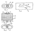
- the two bellows 6 are comparatively flat with a substantially rectangular and laterally rounded cross-section.
- the bellows 6 each have a plurality of laterally drawn inwards Support folds 10 on.
- These folds 10a are usual per se Folds 10, however, so formed that they arcuate into the Intervene inside the bellows 6.
- the support folds 10a enable that the bellows 6 essentially compresses its shape maintains.
- the flat design of the two bellows 6 shown has the main advantage that this is in a rectangular housing 2 take up little space and the interior of the housing 2 is used optimally.
- the housing 2 can therefore have external dimensions be produced, which correspond to the usual keys.
- the two bellows 6, or only a bellows 6 is attached to the holding and guiding part 8. Now the means are used and the lines 27 are connected. The guide parts are now on the top of the bellows 6 7 put on. After snapping buttons 4 and 5 can the interconnected parts in the housing 2 of be used above. Finally, cover 3 snapped onto the holding frame.
Abstract
Description
Die Erfindung betrifft eine Vorrichtung zur pneumatischen Betätigung nach dem Oberbegriff des Anspruchs 1.The invention relates to a device for pneumatic actuation according to the preamble of claim 1.
Eine Vorrichtung der genannten Art ist im Stand der Technik aus der WO 94/23141 bekannt geworden. Bei dieser sind zwei Tasten an einer Seitenwandung angebracht und zwei Bälge sind im Inneren des Spülkastens angeordnet. Mit der einen Taste wird zur Auslösung einer Vollspülung einer der beiden Bälge betätigt und zur Auslösung einer Teilspülung werden mit der anderen Taste beide Bälge gleichzeitig betätigt.A device of the type mentioned is in the prior art WO 94/23141 become known. There are two buttons on this attached to a side wall and two bellows are inside the cistern arranged. With one button it triggers a full flush one of the two bellows actuated and to A partial flush is triggered with the other button Bellows actuated at the same time.
Eine weitere Betätigungsvorrichtung ist aus der CH-A-424 664 bekannt geworden. Diese Vorrichtung ist als Handdrücker ausgebildet und weist einen Druckknopf auf, der im Gehäuse verschiebbar gelagert ist. Das innere Ende des Druckknopfes liegt an einer Membran an, die zur Ausübung eines Druckimpulses deformierbar ist.Another actuating device is known from CH-A-424 664 become. This device is designed as a hand lever and has a push button that is slidable in the housing is stored. The inner end of the push button lies on one Membrane that is deformable to exert a pressure pulse is.
Eine ähnliche Vorrichtung ist aus der DE-C-23 50 189 bekannt geworden. Bei dieser wird zur Ausübung eines Druckimpulses eine gewölbte Gummimembran von Hand eingedrückt oder eine Rohrmembran mit einem Druckknopf zusammengedrückt.A similar device has become known from DE-C-23 50 189. This is used to exercise a pressure pulse domed rubber membrane pressed in by hand or a tubular membrane pressed together with a push button.
Der Erfindung liegt die Aufgabe zugrunde, eine Vorrichtung der genannten Art zu schaffen, die eine Fernauslösung ermöglicht.The invention has for its object a device to create the type mentioned, which enables remote triggering.
Die Aufgabe ist gemäss Anspruch 1 gelöst. The object is achieved according to claim 1.
Die erfindungsgemässe Vorrichtung ermöglicht die Betätigung eines Spülkastens mit zwei unterschiedlichen Spülmengen. Beim Drücken der einen Taste kann am Spülkasten beispielsweise eine Vollspülung und mit der anderen Taste beispielsweise eine Teilspülung ausgelöst werden. Spülkästen mit zwei unterschiedlichen Spülmengen sind an sich seit langem bekannt. Bisher wurde diese aber ausschliesslich durch direkt am Spülkasten gelagerte Tasten ausgelöst. Die erfindungsgemässe Vorrichtung ermöglicht nun eine Fernauslösung auch solcher Spülkästen, die aus ökologischen und ökonomischen Gründen sehr vorteilhaft sind.The device according to the invention enables the actuation of a Cistern with two different flush volumes. When pressing one button on the cistern, for example Full rinse and with the other button, for example, a partial rinse to be triggered. Cisterns with two different ones Flush volumes have long been known per se. So far this has been but only with buttons located directly on the cistern triggered. The device according to the invention now enables one Remote activation of such cisterns, which are ecological and economic reasons are very advantageous.
Nach der Erfindung weist der Druckimpulsgeber zwei Bälge auf, wobei der eine Balg mit der einen Taste und der andere Balg mit der anderen Taste zusammenarbeitet. Sind diese beiden Bälge gemäss einer Weiterbildung der Erfindung seitlich abgeflachte Faltenbälge, so können diese bei kleiner Baugrösse beispielsweise in einer Dose untergebracht werden. Diese Baumasse ermöglichen ein Nachrüsten bereits eingebauter Betätigungstaster. Eine besonders zuverlässige Funktionsweise ist dann gewährleistet, wenn die Faltenbälge seitlich eingezogene Stützfalten aufweisen. Diese Stützfalten verhindern eine unkontrollierte Verformung der Bälge und gewährleisten genau bestimmte Druckimpulse. Dazu dient auch die Weiterbildung, nach welcher die Tasten unterseitig jeweils ein Führungsteil aufweisen, das auf einem Balg aufgesetzt ist und diesen seitlich führt. Für eine Betätigung der Taste wird der Balg dann somit durch diesen Führungsteil geführt.According to the invention, the pressure pulse generator has two bellows, one bellows with one button and the other bellows with the other button works together. Are these two bellows according to a further development of the invention laterally flattened bellows, For example, these can be used for small sizes be housed in a can. Enable this construction mass retrofitting of an already installed push button. A special one reliable functioning is guaranteed if the bellows have support folds drawn in laterally. This Support folds prevent uncontrolled deformation of the Bellows and ensure precisely defined pressure impulses. It serves also the training, according to which the buttons on the underside in each case have a guide part, which is placed on a bellows and leads it to the side. For pressing the button the bellows is then guided through this guide part.
Die beiden Bälge sind nach einer Weiterbildung der Erfindung lösbar an einem Halte- und Führungsteil befestigt, welches in den Bodenteil des Gehäuses eingesetzt ist. Vorzugsweise besitzt dieses Halte- und Führungsteil wenigstens zwei, vorzugsweise drei Befestigungspositionen. Dadurch wird ermöglicht, dass wahlweise zwei oder ein Balg im Gehäuse befestigbar ist. The two bellows are according to a further development of the invention releasably attached to a holding and guiding part, which in the bottom part of the housing is inserted. Preferably owns this holding and guiding part at least two, preferably three mounting positions. This enables that two or one bellows can be fastened in the housing.
Weitere vorteilhafte Merkmale ergeben sich aus den abhängigen Patentansprüchen, der nachfolgenden Beschreibung sowie der Zeichnungen.Further advantageous features result from the dependent ones Claims, the following description and the Drawings.
Ein Ausführungsbeispiel der Erfindung wird nachfolgend anhand der Zeichnungen näher erläutert. Es zeigen:
- Figur 1
- einen Schnitt durch eine erfindungsgemässe Vorrichtung,
Figur 2- einen Schnitt durch die Vorrichtung entlang der Linie II-II gemäss Figur 1,
Figur 3- eine Ansicht der Unterseite eines Balges,
Figur 4- eine Seitenansicht des Balges,
Figur 5- eine Ansicht der Oberseite des Balges, und
Figur 6- eine Ansicht des Befestigungsmittels für die wahlweise Befestigung eines oder zweier Bälge.
- Figure 1
- 2 shows a section through a device according to the invention,
- Figure 2
- 2 shows a section through the device along the line II-II according to FIG. 1,
- Figure 3
- a view of the underside of a bellows,
- Figure 4
- a side view of the bellows,
- Figure 5
- a view of the top of the bellows, and
- Figure 6
- a view of the fastener for the optional attachment of one or two bellows.
Die Vorrichtung 1 ist ein Handdrücker, auch Taster genannt, der
im wesentlichen aus einem Gehäuse 2, einem Deckel 3, zwei Tasten
4 und 5, zwei Bälgen 6 und einem im unteren Teil des Gehäuses
gelagerten Halte- und Führungsteil 8 besteht. Diese Teile
sind lösbar durch Rastmittel und Zusammenstecken miteinander
verbunden. Die einzelnen Teile sind somit ohne Verwendung von
Werkzeugen und zerstörungsfrei auswechselbar. Auch die Montage
erfolgt ohne Verwendung von Werkzeugen durch Rastmittel, die
weiter unten noch näher erläutert werden.The device 1 is a hand lever, also called a button
essentially from a
Das Gehäuse 2 ist dosenförmig ausgebildet und weist in seinem
Boden vier Befestigungsstellen 26 auf, mit denen das Gehäuse mit
hier nicht gezeigten Schrauben in einer Nische einer Gebäudewand
befestigbar ist. Ebenfalls im-Boden sind zwei Öffnungen 24 eingearbeitet,
durch die jeweils eine flexible Druckleitung 27
(Figur- 2) hindurchgezogen werden. Im Innern des Gehäuses 2 sind
diese Druckleitungen 27 jeweils an einem Nippel 9 angeschlossen.The
In das Gehäuse 2 ist ein Halte- und Führungsteil 8 eingesetzt,
an dem die beiden Nippel 9, die beiden Bälge 6, die beiden Tasten
4 und 5 sowie die Rahmenabdeckung 3 lösbar befestigt sind.
Die beiden Nippel 9 sind von der Unterseite des Teils 8 jeweils
luftdicht in einen rohrförmigen, gummielastischen Ansatz 28 eines
Balges 6 eingesetzt. Wie die Figur 2 zeigt, überragt das
obere Ende des Nippels 9 die Öffnung 28 und greift in eine korrespondierende,
hier nicht näher bezeichnete Öffnung des Ansatzes
28 ein. Die Nippel 9 verbinden jeweils eine pneumatische
Leitung 27 mit einem Balg 6.A holding and guiding
Zur Befestigung der beiden Bälge 6 weist das Halte- und Führungsteil
8 gemäss Figur 6 einen Schlitz 14 auf, der eine grosse
kreisförmige Öffnung 14d sowie drei kleinere Erweiterungen 14a,
14b und 14c besitzt. Die Bälge 6 weisen zu ihrer Befestigung in
diesem Schlitz 14 jeweils auf der Unterseite einen tellerförmigen
Ansatz 12 auf, wie die Figur 4 deutlich zeigt. Um einen ersten
Balg am Teil 8 zu befestigen, wird der Teller 12 durch die
grosse Öffnung 14d eingesetzt und der Balg 6 im Schlitz 14 in
Figur 6 nach links verschoben, bis der Teller 12 den Schlitz 14
in die Erweiterung 14a einrastet. Ein zweiter Balg 6 wird ebenfalls
mit seinem Teller 12 durch die Öffnung 14d eingesetzt und
in Figur 6 nach rechts verschoben bis zur Erweiterung 14c. Ist
lediglich ein Balg 6 vorgesehen, so wird dieser in Figur 6 bis
zur Erweiterung 14b verschoben. Die Erweiterung 14b erlaubt somit
die lösbare Befestigung eines einzigen Balges 6 etwa in der
Mitte des Gehäuses 2.To hold the two
Zur Drehsicherung besitzt jeder Balg 6 an seinem Boden zwei angeformte
Nocken 30, die jeweils in eine Öffnung 25 des Teils 8
eingreifen. Der Teller 12 besitzt mittig einen Durchgang, wie
die Figur 2 zeigt. In diesem Durchgang 28 ist ein stutzenförmiger
Ansatz eines Nippels 9 einsetzbar. Der Teller 12 ist aus
gummielastischem Material wie der übrige Teil des Balges 6 und
dichtet den Nippel 9 gegenüber dem Balg 6 ab. Die beiden Nippel
9 sind damit jeweils lösbar und dicht mit einem Balg 6 verbunden.To prevent rotation, each bellows 6 has two molded parts on its
Der Teil 8 weist mehrere nach oben gerichtete elastisch auslenkbare
Rastzungen 16 und 22 zur Befestigung des rahmenförmigen
Deckels 3 und der Tasten 4 und 5 auf. Die Figur 1 zeigt eine der
Rastzungen 16, die mit einer Rastnase in eine Öffnung 15 derRahmenabdeckung
3 eingreift. Vorzugsweise sind mehrere solche Rastzungen
16 am Teil 8 angeformt.The
Die beiden Tasten 4 und 5 sind jeweils haubenförmig ausgebildet
und besitzen gemäss Figur 2, hier am Beispiel der Taste 5 gezeigt,
eine gewölbte obere Wandung 4b und seitlich nach unten in
eine Öffnung 3a der Rahmenabdeckung 3 eingreifende Führungswandung
5a. Die Taste 5 weist eine kleinere Tastfläche auf als die
Taste 4, grundsätzlich sind beide Tasten aber ähnlich ausgebildet.
Die grössere Taste 4 ist zur Auslösung einer Vollspülung
und die kleinere Taste 5 zur Auslösung einer Teilspülung vorgesehen.
Die Tasten 4 und 5 sind durch die genannten Rastzungen 22
mit dem Halte- und Führungsteil 8 verschiebbar gelagert und in
der oberen Position verrastet. Die Tasten 4 und 5 können in der
in den Figuren 1 und 2 gezeigten Position jeweils einzeln nach
unten bewegt werden. Die gezeigte obere Position ist durch einen
oberen Anschlag bestimmt.The two
Wie insbesondere die Figur 2 zeigt, übergreifen die Tasten 4
und 5 jeweils einen Balg 6. Der unterhalb der Taste 4 angeordnete
Balg ist aus zeichnerischen Gründen weggelassen, ist aber
sonst identisch mit dem gezeichneten Balg 6. Bei einer Tastbewegung
an einer Taste 4 bzw. 5 wird der jeweilige Balg 6 durch ein
unterseitig an der Taste angebrachtes, plattenförmiges Führungsteil
7 geführt. Dieses Führungsteil 7 besitzt einen mittigen
Verbindungsteil 31 mit einem unteren Stutzen 21 sowie einem oberen
Stutzen 20. Der Stutzen 20 ist in einen Ansatz 32 eingerastet
Das gleiche gilt selbstverständlich auch für die Taste 5.
Der untere Stutzen 21 greift in einen schlauchförmigen Ansatz 33
des Balges 6 ein und befestigt damit den Balg 6 am Teil 7. Wie
die Figur 2 zeigt, liegt der Balg 6 an seinem oberen Ende unterseitig
am Teil 7 an und ist an diesem seitlich geführt. Das
Teil 7 verhindert somit, dass beim Niederdrücken der Taste 4 das
obere Ende des Balges 6 seitlich ausweichen kann.As FIG. 2 in particular shows, the
Die beiden Bälge 6 sind, wie in den Figuren 3 bis 5 gezeigt,
vergleichsweise flach mit einem im wesentlichen rechteckigen und
seitlich abgerundeten Querschnitt ausgebildet. Zur Stabilisierung
weisen die Bälge 6 jeweils seitlich mehrere nach innen gezogene
Stützfalten 10 auf. Diese Falten 10a sind an sich übliche
Falten 10, jedoch so ausgebildet, dass sie bogenförmig in das
Innere des Balges 6 eingreifen. Die Stützfalten 10a ermöglichen,
dass der Balg 6 beim Zusammendrücken seine Form im wesentlichen
beibehält. Die gezeigte flache Ausbildung der beiden Bälge 6 hat
den wesentlichen Vorteil, dass diese in einem rechteckigen Gehäuse
2 wenig Platz beanspruchen und der Innenraum des Gehäuses
2 optimal genutzt wird. Das Gehäuse 2 kann deshalb mit Aussenmassen
hergestellt werden, welche den üblichen Tasten entsprechen.As shown in FIGS. 3 to 5, the two
Für die besonders einfache Montage werden die beiden Bälge 6,
bzw. lediglich ein Balg 6 am Halte- und Führungsteil 8 befestigt.
Nun werden die Mittel eingesetzt und die Leitungen 27 angeschlossen.
Auf die Oberseite der Bälge 6 werden nun die Führungsteile
7 aufgesetzt. Nach dem Aufrasten der Tasten 4 und 5
können die miteinander verbundenen Teile in das Gehäuse 2 von
oben eingesetzt werden. Schliesslich wird noch die Abdeckung 3
auf den Halterahmen aufgerastet. For particularly simple assembly, the two
Zur Auslösung einer Spülung wird die Taste 4 oder die Taste 5
gedrückt. Dadurch wird der entsprechende Balg 6 durch das sich
nach unten bewegende Führungsteil 7 zusammengedrückt und dadurch
wird der Luftdruck in der Kammer 35 erhöht. Dieser Druckimpuls
wird über die entsprechende Leitung 27 an eine pneumatische Betätigung
eines Spülkastens zur Auslösung einer Spülung weitergegeben.
Pneumatische Betätigungen für Spülkästen sind bekannt und
brauchen hier deshalb nicht erläutert zu werden. Nach der Betätigung
kehrt die entsprechende Taste 4 bzw. 5 infolge der Elastizität
des betätigten Balges 6 und des darin herrschenden
Luftdrucks in die in den Figuren 1 und 2 gezeigte Grundstellung
zurück. Eine separate Feder zur Rückstellung der Tasten 4 und 5
erübrigt sich deshalb.To trigger a rinse,
Claims (9)
- Apparatus for pneumatically operating a WC flushing cistern with a device (4, 5) carried in a housing (2) that operates together with a pressure pulse generator (6) to create a pressure pulse, whereby the device has two buttons (4, 5) and the pressure pulse generator (6) has two bellows (6), and the pressure pulse generator (6) is constructed in such a way that optionally a first or a second pressure pulse can be generated by pressing the one or the other button (4, 5), characterized in that the first bellows operates only together with the first button (4) and the second bellows operates only together with the second button (5) and in that the two bellows (6) together with the buttons (4, 5) are carried in the said housing (2).
- Apparatus according to Claim 1, characterized in that the two bellows (6) are laterally flattened corrugated bellows.
- Apparatus according to Claim 2, characterized in that the two corrugated bellows (6) have an approximately rectangular shape when seen in cross-section relative to each other, whereby the narrow sides are considerably shorter than the wide sides, preferably by a factor of at least two.
- Apparatus according to one of the Claims 1 to 3, characterized in that the corrugated bellows (6) have laterally indented support folds (10a).
- Apparatus according to one of the Claims 1 to 4, characterized in that the buttons (4, 5) are each dome-shaped or bonnet-shaped and are guided in a sliding manner by walls (5a) that engage in the housing (2) at the side.
- Apparatus according to one of the Claims 1 to 5, characterized in that the buttons (4, 5) each have on their undersides a guide component (7) that is superimposed on a bellows (6) and guides the latter at the sides.
- Apparatus according to one of the Claims 1 to 6, characterized in that the buttons (4, 5) have means for guiding (5a) with which they are guided in a sliding manner in the housing (2) and in that these means of guiding (5a) have detent devices (18) for detachably fastening the buttons (4, 5) onto a retaining and guiding component (8).
- Apparatus according to one of the Claims 1 to 7, characterized in that into the housing (2) there is detachably inserted a retaining and guiding component (8) onto which at least the pressure pulse generator (6) is detachably fastened.
- Apparatus according to Claim 8, characterized in that the retaining and guiding component (8) has means for fastening (14) with at least two and preferably three fixing positions (14a, 14b, 14c) in such a way that optionally two or one bellows (6) can be attached.
Applications Claiming Priority (2)
| Application Number | Priority Date | Filing Date | Title |
|---|---|---|---|
| CH287697 | 1997-12-15 | ||
| CH287697 | 1997-12-15 |
Publications (3)
| Publication Number | Publication Date |
|---|---|
| EP0924353A2 EP0924353A2 (en) | 1999-06-23 |
| EP0924353A3 EP0924353A3 (en) | 2000-01-26 |
| EP0924353B1 true EP0924353B1 (en) | 2003-06-04 |
Family
ID=4243565
Family Applications (1)
| Application Number | Title | Priority Date | Filing Date |
|---|---|---|---|
| EP98811139A Expired - Lifetime EP0924353B1 (en) | 1997-12-15 | 1998-11-16 | Device for the pneumatic actuation of a flushing cistern |
Country Status (4)
| Country | Link |
|---|---|
| EP (1) | EP0924353B1 (en) |
| AT (1) | ATE242371T1 (en) |
| AU (1) | AU742152B2 (en) |
| DE (2) | DE59808615D1 (en) |
Families Citing this family (7)
| Publication number | Priority date | Publication date | Assignee | Title |
|---|---|---|---|---|
| ITMI20010276U1 (en) * | 2001-05-16 | 2002-11-18 | Valsir Spa | MODULAR SYSTEM FOR EQUIPMENT OF RINSING BOXES FOR SANITARY EQUIPMENT WITH DIFFERENT OPERATING MODES, AND BOX |
| ITMI20031323A1 (en) * | 2003-06-27 | 2004-12-28 | Valsir Spa | CONTROL DEVICE OF THE DISCHARGE VALVE OF A RINSE BOX. |
| CN101802315B (en) * | 2007-09-20 | 2011-08-31 | 卡罗马工业有限公司 | A pneumatic button assembly for a cistern outlet valve |
| EP2169126B1 (en) | 2008-09-29 | 2012-04-25 | Geberit International AG | Pneumatic activation device |
| WO2012123050A1 (en) | 2011-03-11 | 2012-09-20 | Grohe Ag | Sanitary installation having a flushing function, such as a toilet or urinal |
| DE102022108200A1 (en) | 2022-04-05 | 2023-10-05 | Grohe Ag | Sanitary facility with flushing function |
| DE102022108201A1 (en) | 2022-04-05 | 2023-10-05 | Grohe Ag | Sanitary facility with flushing function |
Family Cites Families (7)
| Publication number | Priority date | Publication date | Assignee | Title |
|---|---|---|---|---|
| CH424664A (en) | 1965-08-27 | 1966-11-15 | Gebert & Cie | Hand lever to operate a cistern |
| CH558080A (en) | 1972-10-14 | 1975-01-15 | Huba Control Ag | ACTUATION BUTTON FOR A SWITCH ACTUATED BY FLUID PRESSURE. |
| CH641225A5 (en) * | 1979-06-05 | 1984-02-15 | Geberit Ag | PNEUMATIC ACTUATING DEVICE ON A Cistern drain valve. |
| US4809367A (en) * | 1986-08-08 | 1989-03-07 | Partall Systems (Proprietary) Limited | Cistern flushing apparatus |
| GB2276640B (en) * | 1993-03-30 | 1996-07-31 | Alan David Somerfield | Improvements in or relating to cisterns |
| IT1280896B1 (en) * | 1995-08-04 | 1998-02-11 | Plastic Investment Holding S A | PNEUMATIC DEVICE FOR ACTIVATING A DRAIN VALVE OF A WC CISTERN |
| DE29808200U1 (en) * | 1997-07-07 | 1998-07-23 | Geberit Technik Ag | Actuator for a drain valve of a toilet cistern |
-
1998
- 1998-11-16 EP EP98811139A patent/EP0924353B1/en not_active Expired - Lifetime
- 1998-11-16 AT AT98811139T patent/ATE242371T1/en active
- 1998-11-16 DE DE59808615T patent/DE59808615D1/en not_active Expired - Lifetime
- 1998-11-21 DE DE29820855U patent/DE29820855U1/en not_active Expired - Lifetime
- 1998-12-14 AU AU97110/98A patent/AU742152B2/en not_active Ceased
Also Published As
| Publication number | Publication date |
|---|---|
| AU9711098A (en) | 1999-07-01 |
| DE59808615D1 (en) | 2003-07-10 |
| EP0924353A2 (en) | 1999-06-23 |
| EP0924353A3 (en) | 2000-01-26 |
| DE29820855U1 (en) | 1999-03-25 |
| AU742152B2 (en) | 2001-12-20 |
| ATE242371T1 (en) | 2003-06-15 |
Similar Documents
| Publication | Publication Date | Title |
|---|---|---|
| EP1236910B1 (en) | Spring-loaded press pin | |
| DE69817651T2 (en) | Switch structure for electronic device | |
| EP0924353B1 (en) | Device for the pneumatic actuation of a flushing cistern | |
| EP0779397B1 (en) | Cover arrangement | |
| DE102011009123B4 (en) | Switch arrangement with manual reset | |
| DE8617785U1 (en) | Actuating device for a concealed cistern with flush interruption | |
| DE4004197C2 (en) | Quick connection device for furniture hinges | |
| DE4201570A1 (en) | ACTUATOR | |
| DE69823305T2 (en) | Automatically adjusting actuating push button for an automatic draft stop and draft stop equipped with the push button | |
| EP3384995B1 (en) | Switch device for a sanitation fitting | |
| EP0131538B1 (en) | Device for mounting an appliance in a support, especially a kitchen work top | |
| DE10250966A1 (en) | Kickdown element for driving pedal sensor has movable arms on base surface of housing and covering cap to close housing | |
| EP0688554B1 (en) | Distributor for aerating apparatus | |
| EP0877125B1 (en) | Mounting frame for sanitary appliances | |
| DE4216855C1 (en) | Paint box for artist - has upwardly open compartment closable by pivotable cover held in closed position by releasable closure | |
| DE4140481C1 (en) | Roof ridge covering strip made in two parts - has one part fixed to ridge board and other to tile connected by pressure activated clips. | |
| DE19527093A1 (en) | Key operated contact system for manual control of electrical functions with contact element | |
| DE2327170C3 (en) | Fastening device for a push button switch | |
| DE3418931A1 (en) | PUSH BUTTON SWITCH | |
| DE202017106831U1 (en) | Rundfußschalter | |
| DE202007000122U1 (en) | Press switch positioning assembly for hand tool, has press switch with cover, where end of switch is elastically implemented with block, and is moved downwardly to disengage block from slot when pressure is exercised on switch | |
| DE10117213A1 (en) | Fixing for a roof strip in vehicle roofs comprises a clip which is fixed in bottom of channel and then has roof strip held secure thereon e.g. by catch | |
| EP1260403A1 (en) | Assembly unit for mounting in an opening in an assembly | |
| CH692751A5 (en) | Hollow body for concrete installation. | |
| WO1996020816A1 (en) | Stapler with spring compartment mechanism |
Legal Events
| Date | Code | Title | Description |
|---|---|---|---|
| PUAI | Public reference made under article 153(3) epc to a published international application that has entered the european phase |
Free format text: ORIGINAL CODE: 0009012 |
|
| AK | Designated contracting states |
Kind code of ref document: A2 Designated state(s): AT BE CH DE DK ES FI FR GB IT LI MC NL SE |
|
| AX | Request for extension of the european patent |
Free format text: AL;LT;LV;MK;RO;SI |
|
| PUAL | Search report despatched |
Free format text: ORIGINAL CODE: 0009013 |
|
| AK | Designated contracting states |
Kind code of ref document: A3 Designated state(s): AT BE CH CY DE DK ES FI FR GB GR IE IT LI LU MC NL PT SE |
|
| AX | Request for extension of the european patent |
Free format text: AL;LT;LV;MK;RO;SI |
|
| 17P | Request for examination filed |
Effective date: 20000212 |
|
| AKX | Designation fees paid |
Free format text: AT BE CH DE DK ES FI FR GB IT LI MC NL SE |
|
| AXX | Extension fees paid |
Free format text: SI PAYMENT 20000212 |
|
| 17Q | First examination report despatched |
Effective date: 20020917 |
|
| GRAH | Despatch of communication of intention to grant a patent |
Free format text: ORIGINAL CODE: EPIDOS IGRA |
|
| GRAH | Despatch of communication of intention to grant a patent |
Free format text: ORIGINAL CODE: EPIDOS IGRA |
|
| GRAA | (expected) grant |
Free format text: ORIGINAL CODE: 0009210 |
|
| AK | Designated contracting states |
Designated state(s): AT BE CH DE DK ES FI FR GB IT LI MC NL SE |
|
| AX | Request for extension of the european patent |
Extension state: SI |
|
| PG25 | Lapsed in a contracting state [announced via postgrant information from national office to epo] |
Ref country code: FI Free format text: LAPSE BECAUSE OF FAILURE TO SUBMIT A TRANSLATION OF THE DESCRIPTION OR TO PAY THE FEE WITHIN THE PRESCRIBED TIME-LIMIT Effective date: 20030604 |
|
| REG | Reference to a national code |
Ref country code: GB Ref legal event code: FG4D Free format text: NOT ENGLISH |
|
| REG | Reference to a national code |
Ref country code: CH Ref legal event code: NV Representative=s name: INFINEON TECHNOLOGIES SCHWEIZ AG Ref country code: CH Ref legal event code: EP |
|
| REF | Corresponds to: |
Ref document number: 59808615 Country of ref document: DE Date of ref document: 20030710 Kind code of ref document: P |
|
| GBT | Gb: translation of ep patent filed (gb section 77(6)(a)/1977) | ||
| PG25 | Lapsed in a contracting state [announced via postgrant information from national office to epo] |
Ref country code: SE Free format text: LAPSE BECAUSE OF FAILURE TO SUBMIT A TRANSLATION OF THE DESCRIPTION OR TO PAY THE FEE WITHIN THE PRESCRIBED TIME-LIMIT Effective date: 20030904 Ref country code: DK Free format text: LAPSE BECAUSE OF FAILURE TO SUBMIT A TRANSLATION OF THE DESCRIPTION OR TO PAY THE FEE WITHIN THE PRESCRIBED TIME-LIMIT Effective date: 20030904 |
|
| PG25 | Lapsed in a contracting state [announced via postgrant information from national office to epo] |
Ref country code: ES Free format text: LAPSE BECAUSE OF FAILURE TO SUBMIT A TRANSLATION OF THE DESCRIPTION OR TO PAY THE FEE WITHIN THE PRESCRIBED TIME-LIMIT Effective date: 20030915 |
|
| PG25 | Lapsed in a contracting state [announced via postgrant information from national office to epo] |
Ref country code: MC Free format text: LAPSE BECAUSE OF NON-PAYMENT OF DUE FEES Effective date: 20031130 |
|
| ET | Fr: translation filed | ||
| PLBE | No opposition filed within time limit |
Free format text: ORIGINAL CODE: 0009261 |
|
| STAA | Information on the status of an ep patent application or granted ep patent |
Free format text: STATUS: NO OPPOSITION FILED WITHIN TIME LIMIT |
|
| 26N | No opposition filed |
Effective date: 20040305 |
|
| REG | Reference to a national code |
Ref country code: CH Ref legal event code: PCAR Free format text: ISLER & PEDRAZZINI AG;POSTFACH 1772;8027 ZUERICH (CH) |
|
| REG | Reference to a national code |
Ref country code: GB Ref legal event code: 732E Free format text: REGISTERED BETWEEN 20100121 AND 20100127 |
|
| REG | Reference to a national code |
Ref country code: CH Ref legal event code: PUE Owner name: GEBERIT INTERNATIONAL AG Free format text: GEBERIT TECHNIK AG#SCHACHENSTRASSE 77#8645 JONA (CH) -TRANSFER TO- GEBERIT INTERNATIONAL AG#SCHACHENSTRASSE 77#8645 JONA (CH) |
|
| REG | Reference to a national code |
Ref country code: NL Ref legal event code: SD Effective date: 20100304 |
|
| REG | Reference to a national code |
Ref country code: FR Ref legal event code: TP |
|
| PGFP | Annual fee paid to national office [announced via postgrant information from national office to epo] |
Ref country code: AT Payment date: 20101112 Year of fee payment: 13 |
|
| PGFP | Annual fee paid to national office [announced via postgrant information from national office to epo] |
Ref country code: CH Payment date: 20111130 Year of fee payment: 14 Ref country code: NL Payment date: 20111124 Year of fee payment: 14 |
|
| PGFP | Annual fee paid to national office [announced via postgrant information from national office to epo] |
Ref country code: BE Payment date: 20111110 Year of fee payment: 14 |
|
| BERE | Be: lapsed |
Owner name: GEBERIT INTERNATIONAL A.G. Effective date: 20121130 |
|
| REG | Reference to a national code |
Ref country code: NL Ref legal event code: V1 Effective date: 20130601 |
|
| REG | Reference to a national code |
Ref country code: CH Ref legal event code: PL |
|
| REG | Reference to a national code |
Ref country code: AT Ref legal event code: MM01 Ref document number: 242371 Country of ref document: AT Kind code of ref document: T Effective date: 20121116 |
|
| PG25 | Lapsed in a contracting state [announced via postgrant information from national office to epo] |
Ref country code: AT Free format text: LAPSE BECAUSE OF NON-PAYMENT OF DUE FEES Effective date: 20121116 Ref country code: CH Free format text: LAPSE BECAUSE OF NON-PAYMENT OF DUE FEES Effective date: 20121130 Ref country code: LI Free format text: LAPSE BECAUSE OF NON-PAYMENT OF DUE FEES Effective date: 20121130 |
|
| PG25 | Lapsed in a contracting state [announced via postgrant information from national office to epo] |
Ref country code: BE Free format text: LAPSE BECAUSE OF NON-PAYMENT OF DUE FEES Effective date: 20121130 Ref country code: NL Free format text: LAPSE BECAUSE OF NON-PAYMENT OF DUE FEES Effective date: 20130601 |
|
| REG | Reference to a national code |
Ref country code: DE Ref legal event code: R082 Ref document number: 59808615 Country of ref document: DE Representative=s name: HOEGER, STELLRECHT & PARTNER PATENTANWAELTE MB, DE Ref country code: DE Ref legal event code: R082 Ref document number: 59808615 Country of ref document: DE Representative=s name: HOEGER, STELLRECHT & PARTNER PATENTANWAELTE, DE |
|
| PGFP | Annual fee paid to national office [announced via postgrant information from national office to epo] |
Ref country code: FR Payment date: 20141119 Year of fee payment: 17 Ref country code: GB Payment date: 20141119 Year of fee payment: 17 Ref country code: DE Payment date: 20141119 Year of fee payment: 17 |
|
| PGFP | Annual fee paid to national office [announced via postgrant information from national office to epo] |
Ref country code: IT Payment date: 20141126 Year of fee payment: 17 |
|
| REG | Reference to a national code |
Ref country code: DE Ref legal event code: R082 Ref document number: 59808615 Country of ref document: DE Representative=s name: HOEGER, STELLRECHT & PARTNER PATENTANWAELTE MB, DE |
|
| REG | Reference to a national code |
Ref country code: DE Ref legal event code: R119 Ref document number: 59808615 Country of ref document: DE |
|
| GBPC | Gb: european patent ceased through non-payment of renewal fee |
Effective date: 20151116 |
|
| PG25 | Lapsed in a contracting state [announced via postgrant information from national office to epo] |
Ref country code: IT Free format text: LAPSE BECAUSE OF NON-PAYMENT OF DUE FEES Effective date: 20151116 |
|
| REG | Reference to a national code |
Ref country code: FR Ref legal event code: ST Effective date: 20160729 |
|
| PG25 | Lapsed in a contracting state [announced via postgrant information from national office to epo] |
Ref country code: DE Free format text: LAPSE BECAUSE OF NON-PAYMENT OF DUE FEES Effective date: 20160601 Ref country code: GB Free format text: LAPSE BECAUSE OF NON-PAYMENT OF DUE FEES Effective date: 20151116 |
|
| PG25 | Lapsed in a contracting state [announced via postgrant information from national office to epo] |
Ref country code: FR Free format text: LAPSE BECAUSE OF NON-PAYMENT OF DUE FEES Effective date: 20151130 |