EP0923971A1 - Verfahren und Vorrichtung zur Beschickung von Absetzbecken - Google Patents
Verfahren und Vorrichtung zur Beschickung von Absetzbecken Download PDFInfo
- Publication number
- EP0923971A1 EP0923971A1 EP98250440A EP98250440A EP0923971A1 EP 0923971 A1 EP0923971 A1 EP 0923971A1 EP 98250440 A EP98250440 A EP 98250440A EP 98250440 A EP98250440 A EP 98250440A EP 0923971 A1 EP0923971 A1 EP 0923971A1
- Authority
- EP
- European Patent Office
- Prior art keywords
- inlet
- sludge
- mixture
- entry cylinder
- clarifier
- Prior art date
- Legal status (The legal status is an assumption and is not a legal conclusion. Google has not performed a legal analysis and makes no representation as to the accuracy of the status listed.)
- Granted
Links
Images


Classifications
-
- B—PERFORMING OPERATIONS; TRANSPORTING
- B01—PHYSICAL OR CHEMICAL PROCESSES OR APPARATUS IN GENERAL
- B01D—SEPARATION
- B01D21/00—Separation of suspended solid particles from liquids by sedimentation
- B01D21/24—Feed or discharge mechanisms for settling tanks
- B01D21/2427—The feed or discharge opening located at a distant position from the side walls
-
- B—PERFORMING OPERATIONS; TRANSPORTING
- B01—PHYSICAL OR CHEMICAL PROCESSES OR APPARATUS IN GENERAL
- B01D—SEPARATION
- B01D21/00—Separation of suspended solid particles from liquids by sedimentation
- B01D21/0024—Inlets or outlets provided with regulating devices, e.g. valves, flaps
-
- B—PERFORMING OPERATIONS; TRANSPORTING
- B01—PHYSICAL OR CHEMICAL PROCESSES OR APPARATUS IN GENERAL
- B01D—SEPARATION
- B01D21/00—Separation of suspended solid particles from liquids by sedimentation
- B01D21/24—Feed or discharge mechanisms for settling tanks
- B01D21/2405—Feed mechanisms for settling tanks
-
- B—PERFORMING OPERATIONS; TRANSPORTING
- B01—PHYSICAL OR CHEMICAL PROCESSES OR APPARATUS IN GENERAL
- B01D—SEPARATION
- B01D21/00—Separation of suspended solid particles from liquids by sedimentation
- B01D21/24—Feed or discharge mechanisms for settling tanks
- B01D21/2444—Discharge mechanisms for the classified liquid
Definitions
- the invention relates to a method and an apparatus for Separating a mixture of purified wastewater and revitalized Sludge, using a device that has a vertical inlet pipe and an entry cylinder arranged concentrically to this has, the mixture of an aeration tank the secondary settling tank by inflowing the mixture from the feed pipe in the entry cylinder and feed of the mixture is fed from the entry cylinder into the secondary clarifier, being in the secondary clarifier by sedimentation of the living Sludge a phase separation between the cleaned wastewater and the animated sludge is carried out, and wherein that purified wastewater after phase separation in an upper one Area on the water surface in a clear water zone the clarifier is led out and the sedimented Sludge under the sludge level at the bottom of the clarifier is discharged via a return sludge discharge.
- DE 27 47 322 A1 describes a method for separating Solids from a liquid in which a sludge mass formed and a liquid containing solids in the sludge mass is introduced, then liquid from the Solids separated, clarified liquid on one level deducted above the sludge mass and sludge concentrate from a lower area of the sludge mass is known.
- a feed stream of a solid containing Liquid introduced down into the sludge mass and due to at least a portion of the feed stream being fed sealing effect of higher density sludge in the Mass of sludge deflected radially and upwards, sludge from the Sludge in the way of the deflected feed stream circulated, deflected feed stream with circulated Mixed sludge and at least part of the mixture deflected feed stream and circulated sludge radially out into a zone above the sludge mass guided.
- the feed stream is Solids containing liquid down into a Sludge mass introduced, which is basically an uncontrolled Prevents the sedimented sludge from being stirred up becomes.
- the introduction is always the same amount, so that an adaptation to different levels of sedimented Sludge and thus an optimal feeding of the feeding system is not available.
- the invention has for its object a method and a device for separating a mixture of purified Sewage and revitalized sludge, using a device which has a vertical inlet pipe and a concentric one this arranged entry cylinder, the mixture of an aeration tank the secondary clarifier by inflowing the Mixture from the inlet pipe into the entry cylinder and Feed the mixture from the feed cylinder into the secondary clarifier is supplied, with in the secondary clarifier Sedimentation of the activated sludge between phases the cleaned wastewater and the activated sludge is carried out and the purified wastewater after the Phase separation in an upper area on the water surface led out of the secondary clarifier in a clear water zone and the sedimented sludge under the sludge level at the bottom of the secondary clarifier via a return sludge discharge is discharged to create the feed of the mixture of purified wastewater and revitalized Mud carried out at an altitude in the secondary clarifier that correlates with the sludge level in the secondary clarifier.
- the object is achieved in that the mixture from purified wastewater and revitalized sludge over the Device in the clarifier in a different, altitude in the area of the mud level through a lower inlet or an upper inlet or by one between the lower inlet and the upper inlet adjustable middle inlet is supplied, the lower Limitation of the lower inflow above the sedimented Solid layer of the activated sludge and the upper one Limitation of the upper inlet below the clear water zone lies.
- the mixture is in the clarifier at a height introduced in which the separation between the purified wastewater and the activated sludge can be carried out optimally can. Accelerated by the formation of macro flakes in the enema the sedimentation process of the activated sludge. In this way, the throughput in the clarifier can a high quality of the treated wastewater.
- the mixture is preferred at a low sludge level through the lower inlet above the sludge level fed to the clarifier.
- the mixture through the upper inlet is sent to the clarifier if the upper limit of the upper inlet in a range between 0.5 m - 1.0 m is under the clear water drain.
- a preferred solution is that the mixture through the adjustable middle inlet to the secondary clarifier the upper limit of the middle inflow between 0 m - 0.5 m below the sludge level.
- the invention comprises a device the device being an inlet pipe and a concentric one to this arranged entry cylinder with a lower inlet and an upper inlet and medium inlets for the Mixture of treated wastewater and activated sludge, the inlet pipe extending through the bottom of the secondary clarifier extends vertically upwards and the Entry cylinder concentrically concentrates the upper section of the inlet pipe encloses and the lower end of the entry cylinder at a predetermined distance above the bottom of the secondary clarifier ends, so that a passage for the sedimented Mud remains open and with the lower inlet on the lower one End and the upper inlet in the upper area of the upper End of the entry cylinder is arranged and the entry cylinder in the area of the clear water zone is closed and with several between the lower inlet and the upper inlet middle inlets are arranged one above the other.
- the perimeter of the entry cylinder may be a polygon, preferably a hexagon, but also be round.
- the inlets at different heights are formed, preferably the heights of the inlets decrease from the upper inlet to the lower inlet.
- the inlets are expediently in two different Heights trained.
- a preferred embodiment is that the inlets in the outer wall of the entry cylinder by opening Closure elements are closed.
- the closure elements can be horizontal and transverse to Flaps arranged along the longitudinal axis of the insertion cylinder be.
- closure elements as blinds are trained.
- closure elements are vertical in the direction of the longitudinal axis of the entry cylinder in each case extend over the height of an inlet.
- a preferred embodiment is that the closure elements are arranged directly on the inlet pipe and have a locking mechanism, the inlets through intermediate floors arranged essentially horizontally to one another are separated from each other by the circumference of the inlet pipe extend to the outer wall of the entry cylinder, the outer wall of the entry cylinder in the area of each Inlet is open.
- the partition walls can be in a fluidically favorable Form be formed.
- a device is centrally located in the clarifier 1 2 for introducing a mixture of activated sludge 8 and cleaned wastewater 11. The mixture is over the device 2 the clarifier 1 from a not shown Aeration tank supplied.
- the activated sludge 8 is separated from the cleaned one Wastewater 11 by the sedimentation of the busy Mud 8.
- the device has an inlet pipe 3 and a concentric one to this arranged entry cylinder 4 with inlets 5; 6; 7 for the mixture.
- the inlet pipe 3 extends through the bottom la of the secondary clarifier 1, preferably at the bottom lowest area vertically upwards, with the entry cylinder 4 the upper section of the inlet pipe 3 concentrically encloses.
- the lower end of the entry cylinder 4 ends in a predetermined distance above the bottom 1a of the secondary clarifier 1, so that a passage for the sedimented Mud 8 remains open.
- a return sludge discharge 10 preferably formed as a sludge thickening space, arranged.
- the secondary clarifier 1 In the upper area of the side wall 1b of the secondary clarifier 1 are one or more clear water drain pipes 13 as clear water drain for draining the cleaned wastewater after sedimentation of the activated sludge 8.
- the cleaned Wastewater can also be used in other ways known per se, for example via channels.
- a sufficient size of the secondary clarifier 1 is a prerequisite for the effectiveness of the separation of the activated sludge 8 from the cleaned wastewater 11. It is from a Subdivision of the clarifier 1 into different zones assumed in the vertical direction. The upper zone is there the clear water zone with a planned minimum level of 0.50 m. It is used for one that starts from the weir edge Mitigate suction and other unavoidable influences, like an uneven loading area. The zone below is the separation zone. Is done in it the distribution of the mixture of activated sludge 8 and purified Wastewater 11. Flocculation processes take place which favor the settling process of the activated sludge 8. The settling process is influenced by the degree of turbulence, caused by the inflow of the mixture.
- the following storage zone is used to hold the from the aeration tank inflowing animated sludge 8. It forms practically an enlargement of the separation zone and effective one with her.
- the animated sludge 8 consists of usually from flakes with a diameter of 10 ⁇ m to 500 ⁇ m.
- the separation of the activated sludge 8 from the cleaned waste water 11 must be done so that as few as possible, individual Flakes of the activated sludge 8 in the clear water zone of the Clarification tank 1 arrive. Individual flakes the size of 10 ⁇ m - 500 ⁇ m diameter can due to their size and thus a low sink rate in the separation zone or clear water zone of secondary clarifier 1 only at one extremely low surface loading can be sedimented.
- the sludge level 9 constantly changes its altitude in the clarifier 1. It is therefore the optimal altitude the inlet 5; 6; 7 essentially depending on the Height of the sludge level 9 set.
- the optimal altitude is empirically between a lower inlet 5 and an upper inlet 7 of the mixture of activated sludge 8 and purified wastewater 11 is determined in the secondary treatment plant 1.
- the lower inlet 5 is set so that the lower limit the inlet 5 above the sedimented solid layer of the activated sludge 8 lies, at the same time the withdrawal of the same via the return sludge discharge 10 is secured.
- a lower setting of the lower inlet 5 can lead to the sedimented solid layer is whirled up. This creates an increased solids content in the course of the clarification.
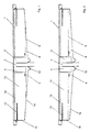
- the sludge level is low 9 the lower inlet 5 with its lower limit above the sludge level 9, as shown in Fig. 1.
- the upper inlet 7 is set so that no introduction of the mixture takes place within the clear water zone. This is achieved by the upper inlet 7 with its upper one Limitation in a range between 0.5 m - 1.0 m below the Clear water drain is located.
- middle inflows 6 adjustable, with a middle inflow 6 is shown in Fig. 2.
- the measurement of the sludge level 9 takes place continuously in the clarifier 1 with measuring methods known per se. After the measurement of the height of the sludge level 9 becomes the mixture from revitalized sludge 8 and purified waste water 11 through one of the middle inlets 6 between 0 m - 0.5 m below of the sludge level 9, preferably at a height of 0.3 m 0.4 m, initiated. It is always between the sludge level 9 and the upper edge of the corresponding middle inlet 6 measured. There is a medium influx in examinations 6 between 0.3 m - 0.4 m the lowest solids content result in the clarification of the clarification. An introduction to the mixture much deeper than 0.5 m below the sludge level 9 can interfere with sedimentation of the busy Mud 8 lead and thus an increase in solid particles cause in the cleaned wastewater 11.
- FIGS. 1-3 is an embodiment of the device 2 according to FIGS. 1-3 for introducing the mixture of animated Mud 8 and purified wastewater 11 shown.
- the device 2 has the vertical inlet pipe 3 and the concentric to this arranged entry cylinder 4 with the Inlets 5; 6; 7 for the mixture of animated sludge 8 and purified wastewater 11.
- the lower end of the entry cylinder 4 ends at a predetermined distance above the ground la of the clarifier 1. The passage for the sedimented Sludge 8 to the return sludge discharge 10 is thus free.
- the entry cylinder 4 is a polygon, preferably a Hexagon, trained. This makes them approximately uniform Flow conditions when the mixture enters through the predetermined inlets 5; 6; 7 in the clarifier 1 reached.
- Another favorable outer shape has a round entry cylinder 4 on.
- Fig. 4 it is shown that the entry cylinder 4 a lower inlet 5 at its lower end and an upper inlet 7 has in the region of its upper end. In the area the clear water zone, the upper end of which is the water surface 12 forms, the entry cylinder 4 is closed.
- Inlets 5; 6; 7 can have a different height, the height of inlets 5; 6; 7 decreases towards the bottom.
- Inlets 5; 6; 7 are shown at two different heights. The amount of the inflows 5; 6; 7 is essentially dependent of the volume flow flowing through them.
- inlets 5; 6; 7 basically just below the sludge level 9 open.
- the opening and closing processes are controlled via known control devices.
- closure of the inlets 5; 6; 7 can within the scope of the invention also in another way, for example by means of closure elements in the form of a blind. It is also possible, the closure elements vertically in the area of each Inlet 5; 6; 7 apply.
- 6 and 7 is a further embodiment of the device 2 shown. This corresponds in their arrangement and the structure of the device 2 described above.
- the closure elements are immediate arranged on the inlet pipe 3. You assign one Locking mechanism 18 on in different ways can be trained.
- Inlets 5; 6; 7 are arranged essentially horizontally Intermediate floors separated from each other Flow of the mixture from the inlet pipe 3 to the outer wall of the entry cylinder 4 can be adapted.
- any sector 15 has an opening on the outer wall of the entry cylinder 4 16 and on the circumference of the inlet pipe 3 a closable pipe opening 19 on.
- the training is part of the method according to the invention further forms of the device 2 possible.
Landscapes
- Chemical & Material Sciences (AREA)
- Chemical Kinetics & Catalysis (AREA)
- Activated Sludge Processes (AREA)
- Electrical Discharge Machining, Electrochemical Machining, And Combined Machining (AREA)
- Treatment Of Sludge (AREA)
- Separation Of Suspended Particles By Flocculating Agents (AREA)
Abstract
Description
- der Höhe des Schlammspiegels im Nachklärbecken,
- dem Volumenstrom im mittleren Zulauf,
- dem Volumenstrom im Rücklaufschlammabzug,
- dem Trockensubstanzgehalt des Gemisches aus belebtem Schlamm und dem gereinigten Abwasser,
- dem Schlammvolumenindex des belebten Schlammes.
- Fig. 1
- ein Nachklärbecken mit einer Vorrichtung zum Einleiten eines Gemisches aus belebtem Schlamm und gereinigtem Abwasser in schematischer Darstellung,
- Fig. 2
- das Nachklärbecken mit der Vorrichtung nach Fig. 1 mit einem geänderten Zulauf,
- Fig. 3
- das Nachklärbecken mit der Vorrichtung nach Fig. 1 mit einer weiteren Änderung des Zulaufes,
- Fig. 4
- die Vorrichtung zum Einleiten des Gemisches aus belebtem Schlamm und gereinigtem Abwasser in perspektivischer Darstellung,
- Fig. 5
- die Draufsicht auf die Vorrichtung nach Fig. 4,
- Fig. 6
- die Vorrichtung nach Fig. 4 in einer weiteren Ausführungsform,
- Fig. 7
- die Draufsicht auf die Vorrichtung nach Fig. 6.
- der Höhe des Schlammspiegels 9 im Nachklärbecken 1,
- dem Volumenstrom im mittleren Zulauf 6,
- dem Volumenstrom im Rücklaufschlammabzug 10,
- dem Trockensubstanzgehalt des Gemisches aus belebtem Schlamm 8 und gereinigtem Abwasser 11,
- dem Schlammvolumenindex des belebten Schlammes 8.
- Beim Austritt aus dem Eintragzylinder 4 wird ein Aufwirbeln einzelner Festteilchen nach oben behindert.
- Das Öffnen der Klappe 14 erfolgt in Richtung der Trennzone und nicht in Richtung der sedimentierten Feststoffschicht, so daß ein leichtes Öffnen möglich ist.
- 1
- Nachklärbecken
- 1a
- Boden
- 1b
- Seitenwand
- 2
- Vorrichtung
- 3
- Zulaufrohr
- 4
- Eintragzylinder
- 5
- unterer Zulauf
- 6
- mittlerer Zulauf
- 7
- oberer Zulauf
- 8
- (belebter) Schlamm
- 9
- Schlammspiegel
- 10
- Rücklaufschlammabzug
- 11
- gereinigtes Abwasser
- 12
- Wasseroberfläche
- 13
- Klarwasserabzugsrohr
- 14
- Klappe
- 15
- Sektor
- 16
- Öffnung
- 17
- Zwischenwand
- 18
- Schließmechanismus
- 19
- Rohröffnung
Claims (20)
- Die Erfindung betrifft ein Verfahren und eine Vorrichtung zum Trennen eines Gemisches aus gereinigtem Abwasser und belebtem Schlamm, wobei über eine Vorrichtung, die ein vertikales Zulaufrohr sowie einen konzentrisch zu diesem angeordneten Eintragzylinder aufweist, das Gemisch aus einem Belebungsbecken dem Nachklärbecken durch Einströmen des Gemisches aus dem Zulaufrohr in den Eintragzylinder und Zulaufen des Gemisches aus dem Eintragzylinder in das Nachklärbecken zugeführt wird, wobei in dem Nachklärbekken durch Sedimentation des belebten Schlammes eine Phasentrennung zwischen dem gereinigten Abwasser und dem belebten Schlamm durchgeführt wird und wobei das gereinigte Abwasser nach der Phasentrennung in einem oberen Bereich an der Wasseroberfläche in einer Klarwasserzone aus dem Nachklärbecken herausgeführt wird und der sedimentierte Schlamm unter dem Schlammspiegel am Boden des Nachklärbeckens über einen Rücklaufschlammabzug abgeführt wird, dadurch gekennzeichnet, daß das Gemisch aus gereinigtem Abwasser (11) und belebtem Schlamm (8) über die Vorrichtung (2) in das Nachklärbecken (1) jeweils in einer unterschiedlichen, im Bereich des Schlammspiegels (9) liegenden Höhenlage durch einen unteren Zulauf (5) oder einen oberen Zulauf (7) oder durch einen zwischen dem unteren Zulauf (5) und dem oberen Zulauf (7) einstellbaren mittleren Zulauf (6) zugeführt wird, wobei die untere Begrenzung des unteren Zulaufes (5) oberhalb der sedimentierten Feststoffschicht des belebten Schlammes (8) und die obere Begrenzung des oberen Zulaufes (7) unterhalb der Klarwasserzone liegt.
- Verfahren nach Anspruch 1, dadurch gekennzeichnet, daß bei einem niedrigen Schlammspiegel (9) das Gemisch durch den unteren Zulauf (5) oberhalb des Schlammspiegels (9) dem Nachklärbecken (1) zugeführt wird.
- Verfahren nach Anspruch 1, dadurch gekennzeichnet, daß das Gemisch durch den oberen Zulauf (7) dem Nachklärbecken (1) zugeführt wird, wenn die obere Begrenzung des oberen Zulaufes (7) in einem Bereich zwischen 0,5 m - 1,0 m unter dem Klarwasserabzug liegt.
- Verfahren nach Anspruch 1, dadurch gekennzeichnet, daß das Gemisch durch den einstellbaren mittleren Zulauf (6) dem Nachklärbecken (1) zugeführt wird, wobei die obere Begrenzung des mittleren Zulaufes (6) zwischen 0 m - 0,5 m unterhalb des Schlammspiegels (9) liegt.
- Verfahren nach Anspruch 1, dadurch gekennzeichnet, daß die obere Begrenzung des mittleren Zulaufes (6) zwischen 0,3 m - 0,4 m unterhalb des Schlammspiegels (9) liegt.
- Verfahren nach Anspruch 1, dadurch gekennzeichnet, daß die optimale Höhenlage des mittleren Zulaufes (6) empirisch in Abhängigkeit von einem oder mehreren der folgenden Faktoren eingestellt wird:der Höhe des Schlammspiegels (9) im Nachklärbecken (1),dem Volumenstrom im mittleren Zulauf (6),dem Volumenstrom im Rücklaufschlammabzug (10),dem Trockensubstanzgehalt des Gemisches aus belebtem Schlamm (8) und dem gereinigten Abwasser (11),dem Schlammvolumenindex des belebten Schlammes (8).
- Vorrichtung zur Durchführung des Verfahrens nach Anspruch 1, dadurch gekennzeichnet, daß die Vorrichtung (2) ein Zulaufrohr (3) sowie einen konzentrisch zu diesem angeordneten Eintragzylinder (4) mit einem unteren Zulauf (5) und einem oberen Zulauf (7) sowie einem mittleren Zulauf (6) für das Gemisch aus gereinigtem Abwasser (11) und belebten Schlamm (8) aufweist, wobei das Zulaufrohr (3) sich durch den Boden (1a) des Nachklärbeckens (1) vertikal nach oben erstreckt und wobei der Eintragzylinder (4) den oberen Abschnitt des Zulaufrohres (3) konzentrisch umschließt und das untere Ende des Eintragzylinders (4) in einem vorbestimmten Abstand über dem Boden (1a) des Nachklärbeckens (1) endet, so daß ein Durchtritt für den sedimentierten Schlamm (8) offen bleibt und wobei der untere Zulauf (5) an dem unteren und der obere Zulauf (7) im oberen Bereich des oberen Endes des Eintragzylinders (4) angeordnet ist und der Eintragzylinder (4) im Bereich der Klarwasserzone geschlossen ist und wobei zwischen dem unteren Zulauf (5) und dem oberen Zulauf (7) mehrere mittlere Zuläufe (6) übereinander liegend angeordnet sind.
- Vorrichtung nach Anspruch 7, dadurch gekennzeichnet, daß der Umfang des Eintragzylinders (4) als ein Vieleck, vorzugsweise ein Sechseck, ausgebildet ist.
- Vorrichtung nach Anspruch 7, dadurch gekennzeichnet, daß der Umfang des Eintragzylinders (4) rund ausgebildet ist.
- Vorrichtung nach Anspruch 7, dadurch gekennzeichnet, daß die Zuläufe (5; 6; 7) mit unterschiedlichen Höhen ausgebildet sind.
- Vorrichtung nach Anspruch 10, dadurch gekennzeichnet, daß die Höhen der Zuläufe (5; 6; 7) von dem oberen Zulauf (7) bis zu dem unteren Zulauf (5) abnehmen.
- Vorrichtung nach Anspruch 10, dadurch gekennzeichnet, daß die Zuläufe (5; 6; 7) in zwei unterschiedlichen Höhen ausgebildet sind.
- Vorrichtung nach Anspruch 10, dadurch gekennzeichnet, daß die Zuläufe (5; 6; 7) an der Außenwand des Eintragzylinders (4) durch zu öffnende Verschlußelemente verschlossen sind.
- Vorrichtung nach Anspruch 13, dadurch gekennzeichnet, daß die Verschlußelemente als horizontal und quer zur Längsachse des Eintragzylinders (4) angeordnete Klappen (14) ausgebildet sind.
- Vorrichtung nach Anspruch 13, dadurch gekennzeichnet, daß die Verschlußelemente als Jalousien ausgebildet sind.
- Vorrichtung nach Anspruch 13, dadurch gekennzeichnet, daß sich die Verschlußelemente vertikal in Richtung der Längsachse des Eintragzylinders (4) jeweils über die Höhe eines Zulaufes (5; 6; 7) erstrecken.
- Vorrichtung nach Anspruch 7, dadurch gekennzeichnet, daß die Verschlußelemente unmittelbar am Zulaufrohr (3) angeordnet sind und einen Schließmechanismus (18) aufweisen, wobei die Zuläufe (5; 6; 7) durch im wesentlichen horizontal zueinander angeordnete Zwischenböden voneinander getrennt sind, die sich von dem Umfang des Zulaufrohres (3) bis zu der Außenwand des Eintragzylinders (4) erstrecken, wobei die Außenwand des Eintragzylinders (4) im Bereich jedes Zulaufes (5; 6; 7) offen ist.
- Vorrichtung nach Anspruch 18, dadurch gekennzeichnet, daß die Zwischenböden dem Strömungsverlauf des Gemisches vom Zulaufrohr (3) zur Außenwand des Eintragzylinders (4) angepaßt sind.
- Vorrichtung nach Anspruch 18, dadurch gekennzeichnet, daß im Bereich der Zuläufe (5; 6; 7) der Eintragzylinder (4) in einzelne Sektoren (15) unterteilt ist, die durch vertikale Zwischenwände (17) voneinander getrennt sind, wobei jeder Sektor (15) in der Außenwand des Eintragzylinders (4) eine Öffnung (16) und am Umfang des Zulaufrohres (3) eine verschließbare Rohröffnung (19) aufweist.
- Vorrichtung nach Anspruch 20, dadurch gekennzeichnet, daß die Zwischenwände (17) in einer strömungstechnisch günstigen Form ausgebildet sind.
Applications Claiming Priority (2)
| Application Number | Priority Date | Filing Date | Title |
|---|---|---|---|
| DE19758360A DE19758360C2 (de) | 1997-12-22 | 1997-12-22 | Verfahren und Vorrichtung zum Trennen eines Gemisches aus gereinigtem Abwasser und belebtem Schlamm |
| DE19758360 | 1997-12-22 |
Publications (2)
| Publication Number | Publication Date |
|---|---|
| EP0923971A1 true EP0923971A1 (de) | 1999-06-23 |
| EP0923971B1 EP0923971B1 (de) | 2003-05-14 |
Family
ID=7853663
Family Applications (1)
| Application Number | Title | Priority Date | Filing Date |
|---|---|---|---|
| EP98250440A Expired - Lifetime EP0923971B1 (de) | 1997-12-22 | 1998-12-17 | Verfahren und Vorrichtung zur Beschickung von Absetzbecken |
Country Status (3)
| Country | Link |
|---|---|
| EP (1) | EP0923971B1 (de) |
| AT (1) | ATE240145T1 (de) |
| DE (2) | DE19758360C2 (de) |
Cited By (4)
| Publication number | Priority date | Publication date | Assignee | Title |
|---|---|---|---|---|
| WO2003084635A1 (de) * | 2002-04-04 | 2003-10-16 | Pahl, Klaus | Absetzbecken |
| EP1584609A1 (de) * | 2004-04-06 | 2005-10-12 | H.H. Ide | Verfahren und Fabrikanlage zur Herstellung von Gülle aus Schlammdünger |
| US10967301B2 (en) | 2018-08-14 | 2021-04-06 | Hydrograv Gmbh | Settling tank and methods for guiding partial flows in the inflow area of settling tanks |
| CN114455679A (zh) * | 2022-01-26 | 2022-05-10 | 浙江杰嘉环保设备有限公司 | 可移动泥水分离装置 |
Families Citing this family (1)
| Publication number | Priority date | Publication date | Assignee | Title |
|---|---|---|---|---|
| DE19950733C1 (de) | 1999-10-23 | 2001-05-23 | Bertram Botsch | Vorrichtung zur Beruhigung einer Einlaufströmung in runden oder polygonalen Becken in Kläranlagen |
Citations (7)
| Publication number | Priority date | Publication date | Assignee | Title |
|---|---|---|---|---|
| US2053636A (en) * | 1933-03-20 | 1936-09-08 | Link Belt Co | Settling tank |
| GB463213A (en) * | 1935-12-19 | 1937-03-24 | Charles Davis | Improvements relating to sedimentation tanks or reservoirs |
| US2205199A (en) * | 1937-08-20 | 1940-06-18 | Dorr Co Inc | Sedimentation |
| US2678730A (en) * | 1951-02-02 | 1954-05-18 | Dorr Co | Flocculation and sedimentation |
| GB847203A (en) * | 1958-10-18 | 1960-09-07 | Rudolf Lautrich | Method and device for passing a liquid through containers or basins |
| JPS594407A (ja) * | 1982-06-30 | 1984-01-11 | Mitsubishi Heavy Ind Ltd | 濃縮槽 |
| GB2293988A (en) * | 1994-10-14 | 1996-04-17 | Univ Bristol | Sedimentation tanks |
Family Cites Families (2)
| Publication number | Priority date | Publication date | Assignee | Title |
|---|---|---|---|---|
| DE4437330C2 (de) * | 1994-10-19 | 1999-12-09 | Herwig Ute | Einlaufsystem für runde Nachklärbecken |
| DE9419662U1 (de) * | 1994-12-08 | 1995-02-02 | Passavant-Werke Ag, 65326 Aarbergen | Abscheidebecken für mit Sink- und/oder Schwimmstoffen befrachtete Abwässer |
-
1997
- 1997-12-22 DE DE19758360A patent/DE19758360C2/de not_active Expired - Lifetime
-
1998
- 1998-12-17 DE DE59808349T patent/DE59808349D1/de not_active Expired - Fee Related
- 1998-12-17 AT AT98250440T patent/ATE240145T1/de active
- 1998-12-17 EP EP98250440A patent/EP0923971B1/de not_active Expired - Lifetime
Patent Citations (7)
| Publication number | Priority date | Publication date | Assignee | Title |
|---|---|---|---|---|
| US2053636A (en) * | 1933-03-20 | 1936-09-08 | Link Belt Co | Settling tank |
| GB463213A (en) * | 1935-12-19 | 1937-03-24 | Charles Davis | Improvements relating to sedimentation tanks or reservoirs |
| US2205199A (en) * | 1937-08-20 | 1940-06-18 | Dorr Co Inc | Sedimentation |
| US2678730A (en) * | 1951-02-02 | 1954-05-18 | Dorr Co | Flocculation and sedimentation |
| GB847203A (en) * | 1958-10-18 | 1960-09-07 | Rudolf Lautrich | Method and device for passing a liquid through containers or basins |
| JPS594407A (ja) * | 1982-06-30 | 1984-01-11 | Mitsubishi Heavy Ind Ltd | 濃縮槽 |
| GB2293988A (en) * | 1994-10-14 | 1996-04-17 | Univ Bristol | Sedimentation tanks |
Non-Patent Citations (1)
| Title |
|---|
| PATENT ABSTRACTS OF JAPAN vol. 008, no. 077 (C - 218) 10 April 1984 (1984-04-10) * |
Cited By (7)
| Publication number | Priority date | Publication date | Assignee | Title |
|---|---|---|---|---|
| WO2003084635A1 (de) * | 2002-04-04 | 2003-10-16 | Pahl, Klaus | Absetzbecken |
| EP1354614A1 (de) * | 2002-04-04 | 2003-10-22 | Armbruster, Martin, Dipl.-Ing. | Absetzbecken |
| EP1607127A3 (de) * | 2002-04-04 | 2006-08-16 | hydrograv GmbH | Absetzbecken |
| EP1584609A1 (de) * | 2004-04-06 | 2005-10-12 | H.H. Ide | Verfahren und Fabrikanlage zur Herstellung von Gülle aus Schlammdünger |
| US10967301B2 (en) | 2018-08-14 | 2021-04-06 | Hydrograv Gmbh | Settling tank and methods for guiding partial flows in the inflow area of settling tanks |
| CN114455679A (zh) * | 2022-01-26 | 2022-05-10 | 浙江杰嘉环保设备有限公司 | 可移动泥水分离装置 |
| CN114455679B (zh) * | 2022-01-26 | 2023-07-28 | 浙江杰嘉环保设备有限公司 | 可移动泥水分离装置 |
Also Published As
| Publication number | Publication date |
|---|---|
| DE19758360A1 (de) | 1999-07-01 |
| DE59808349D1 (de) | 2003-06-18 |
| EP0923971B1 (de) | 2003-05-14 |
| DE19758360C2 (de) | 2000-01-13 |
| ATE240145T1 (de) | 2003-05-15 |
Similar Documents
| Publication | Publication Date | Title |
|---|---|---|
| DE60210800T2 (de) | Vorrichtung und verfahren zur sedimentation von mineralschlämmen | |
| DE69600998T2 (de) | Verfahren und vorrichtung zur trennung von nicht löslichen teilchen aus einer flüssigkeit | |
| DE7138603U (de) | Vorrichtung zur mechanisch-chemischen Wasseraufbereitung und Abwasserbehandlung | |
| DE3117061A1 (de) | Abwasserbehandlungssystem mit einer integralen, in dem kanal angeordneten klaervorrichtung | |
| DE3812715A1 (de) | Absetzbehaelter fuer eine belebtschlamm-abwasser-suspension | |
| DE69100360T2 (de) | Vorrichtung zur kontinuierlichen Reinigung von Flüssigkeiten. | |
| WO1984004295A1 (en) | Method and plant for the biological purification of waste water | |
| EP0923971B1 (de) | Verfahren und Vorrichtung zur Beschickung von Absetzbecken | |
| CH615597A5 (en) | Process and apparatus for settling settleable particles contained in liquids | |
| DE2129349C3 (de) | Schwebefilter-Klärvorrichtung zum Klären von Flüssigkeiten | |
| DE2824387C2 (de) | ||
| CH384485A (de) | Verfahren und Vorrichtung zur Klärung von Flüssigkeiten, insbesondere Abwasser | |
| DE1517551C3 (de) | Wasseraufbereitungs- oder Abwasserbehandlungsanlage | |
| DE3330696A1 (de) | Anlage zum anaeroben abbau organischer substrate | |
| EP0998341A1 (de) | Verfahren und vorrichtung zum trennen von stoffen und leiteinrichtung hierfür | |
| DE3708342C2 (de) | ||
| WO1992012936A1 (de) | Vorrichtung zur biologischen reinigung von abwasser | |
| DE2728585B2 (de) | Vorrichtung zur anaeroben Reinigung von Abwasser | |
| DE19649814C2 (de) | Sedimentationsbecken mit rechteckigem Grundriß zum Abscheiden von Schlamm aus Abwasser | |
| DE4025465C1 (en) | Waste water rain catch basin - has circular funnel with sludge sump and tangential inlet flow | |
| DE4312540C1 (de) | Verfahren zur Abtrennung von Feststoffen aus einer Suspension sowie Vorrichtung zu seiner Durchführung | |
| EP1138363B1 (de) | Vorrichtung zum Abziehen von gereinigtem Wasser aus einem Behälter bei der biologischen Reinigung von Abwasser | |
| DE102006020273B4 (de) | Vorrichtung und Verfahren zum Reinigen von Abwasser | |
| DE68909212T2 (de) | Trennverfahren. | |
| CH650230A5 (en) | Device for separating solids from liquids |
Legal Events
| Date | Code | Title | Description |
|---|---|---|---|
| PUAI | Public reference made under article 153(3) epc to a published international application that has entered the european phase |
Free format text: ORIGINAL CODE: 0009012 |
|
| AK | Designated contracting states |
Kind code of ref document: A1 Designated state(s): AT BE CH DE DK FR GB LI NL SE |
|
| AX | Request for extension of the european patent |
Free format text: AL;LT;LV;MK;RO;SI |
|
| 17P | Request for examination filed |
Effective date: 19990601 |
|
| AKX | Designation fees paid |
Free format text: AT BE CH DE DK FR GB LI NL SE |
|
| 17Q | First examination report despatched |
Effective date: 20010906 |
|
| RAP1 | Party data changed (applicant data changed or rights of an application transferred) |
Owner name: RICHTER, EWALD Owner name: BERLINER WASSERBETRIEBE ANSTALT D. OEFFENTLICHEN R |
|
| GRAH | Despatch of communication of intention to grant a patent |
Free format text: ORIGINAL CODE: EPIDOS IGRA |
|
| GRAH | Despatch of communication of intention to grant a patent |
Free format text: ORIGINAL CODE: EPIDOS IGRA |
|
| GRAA | (expected) grant |
Free format text: ORIGINAL CODE: 0009210 |
|
| AK | Designated contracting states |
Designated state(s): AT BE CH DE DK FR GB LI NL SE |
|
| PG25 | Lapsed in a contracting state [announced via postgrant information from national office to epo] |
Ref country code: NL Free format text: LAPSE BECAUSE OF FAILURE TO SUBMIT A TRANSLATION OF THE DESCRIPTION OR TO PAY THE FEE WITHIN THE PRESCRIBED TIME-LIMIT Effective date: 20030514 Ref country code: FR Free format text: LAPSE BECAUSE OF FAILURE TO SUBMIT A TRANSLATION OF THE DESCRIPTION OR TO PAY THE FEE WITHIN THE PRESCRIBED TIME-LIMIT Effective date: 20030514 |
|
| REG | Reference to a national code |
Ref country code: GB Ref legal event code: FG4D Free format text: NOT ENGLISH |
|
| REG | Reference to a national code |
Ref country code: CH Ref legal event code: EP |
|
| REF | Corresponds to: |
Ref document number: 59808349 Country of ref document: DE Date of ref document: 20030618 Kind code of ref document: P |
|
| PG25 | Lapsed in a contracting state [announced via postgrant information from national office to epo] |
Ref country code: SE Free format text: LAPSE BECAUSE OF FAILURE TO SUBMIT A TRANSLATION OF THE DESCRIPTION OR TO PAY THE FEE WITHIN THE PRESCRIBED TIME-LIMIT Effective date: 20030814 Ref country code: DK Free format text: LAPSE BECAUSE OF FAILURE TO SUBMIT A TRANSLATION OF THE DESCRIPTION OR TO PAY THE FEE WITHIN THE PRESCRIBED TIME-LIMIT Effective date: 20030814 |
|
| REG | Reference to a national code |
Ref country code: CH Ref legal event code: NV Representative=s name: PATENTANWAELTE FELDMANN & PARTNER AG |
|
| GBT | Gb: translation of ep patent filed (gb section 77(6)(a)/1977) | ||
| NLV1 | Nl: lapsed or annulled due to failure to fulfill the requirements of art. 29p and 29m of the patents act | ||
| PG25 | Lapsed in a contracting state [announced via postgrant information from national office to epo] |
Ref country code: BE Free format text: LAPSE BECAUSE OF NON-PAYMENT OF DUE FEES Effective date: 20031231 |
|
| PLBE | No opposition filed within time limit |
Free format text: ORIGINAL CODE: 0009261 |
|
| STAA | Information on the status of an ep patent application or granted ep patent |
Free format text: STATUS: NO OPPOSITION FILED WITHIN TIME LIMIT |
|
| 26N | No opposition filed |
Effective date: 20040217 |
|
| EN | Fr: translation not filed | ||
| BERE | Be: lapsed |
Owner name: *RICHTER EWALD Effective date: 20031231 Owner name: *BERLINER WASSERBETRIEBE ANSTALT D. OFFENTLICHEN R Effective date: 20031231 |
|
| PG25 | Lapsed in a contracting state [announced via postgrant information from national office to epo] |
Ref country code: DE Free format text: LAPSE BECAUSE OF NON-PAYMENT OF DUE FEES Effective date: 20040701 |
|
| PGFP | Annual fee paid to national office [announced via postgrant information from national office to epo] |
Ref country code: GB Payment date: 20141216 Year of fee payment: 17 |
|
| GBPC | Gb: european patent ceased through non-payment of renewal fee |
Effective date: 20151217 |
|
| PG25 | Lapsed in a contracting state [announced via postgrant information from national office to epo] |
Ref country code: GB Free format text: LAPSE BECAUSE OF NON-PAYMENT OF DUE FEES Effective date: 20151217 |
|
| PGFP | Annual fee paid to national office [announced via postgrant information from national office to epo] |
Ref country code: AT Payment date: 20171215 Year of fee payment: 20 Ref country code: CH Payment date: 20171221 Year of fee payment: 20 |
|
| REG | Reference to a national code |
Ref country code: CH Ref legal event code: PL |
|
| REG | Reference to a national code |
Ref country code: AT Ref legal event code: MK07 Ref document number: 240145 Country of ref document: AT Kind code of ref document: T Effective date: 20181217 |