EP0922862A2 - Axialventilator für Lüftungsanlagen - Google Patents
Axialventilator für Lüftungsanlagen Download PDFInfo
- Publication number
- EP0922862A2 EP0922862A2 EP98122961A EP98122961A EP0922862A2 EP 0922862 A2 EP0922862 A2 EP 0922862A2 EP 98122961 A EP98122961 A EP 98122961A EP 98122961 A EP98122961 A EP 98122961A EP 0922862 A2 EP0922862 A2 EP 0922862A2
- Authority
- EP
- European Patent Office
- Prior art keywords
- insert ring
- axial fan
- impeller
- blades
- housing
- Prior art date
- Legal status (The legal status is an assumption and is not a legal conclusion. Google has not performed a legal analysis and makes no representation as to the accuracy of the status listed.)
- Granted
Links
- 239000000779 smoke Substances 0.000 claims abstract description 14
- 239000000463 material Substances 0.000 claims abstract description 6
- 238000009423 ventilation Methods 0.000 claims description 17
- 238000000605 extraction Methods 0.000 claims description 11
- 239000000835 fiber Substances 0.000 claims description 2
- 239000003779 heat-resistant material Substances 0.000 claims 1
- 239000007789 gas Substances 0.000 description 3
- 239000011324 bead Substances 0.000 description 1
- 230000001680 brushing effect Effects 0.000 description 1
- 239000000567 combustion gas Substances 0.000 description 1
- 230000002093 peripheral effect Effects 0.000 description 1
Images


Classifications
-
- F—MECHANICAL ENGINEERING; LIGHTING; HEATING; WEAPONS; BLASTING
- F04—POSITIVE - DISPLACEMENT MACHINES FOR LIQUIDS; PUMPS FOR LIQUIDS OR ELASTIC FLUIDS
- F04D—NON-POSITIVE-DISPLACEMENT PUMPS
- F04D29/00—Details, component parts, or accessories
- F04D29/08—Sealings
- F04D29/16—Sealings between pressure and suction sides
- F04D29/161—Sealings between pressure and suction sides especially adapted for elastic fluid pumps
- F04D29/164—Sealings between pressure and suction sides especially adapted for elastic fluid pumps of an axial flow wheel
-
- F—MECHANICAL ENGINEERING; LIGHTING; HEATING; WEAPONS; BLASTING
- F04—POSITIVE - DISPLACEMENT MACHINES FOR LIQUIDS; PUMPS FOR LIQUIDS OR ELASTIC FLUIDS
- F04D—NON-POSITIVE-DISPLACEMENT PUMPS
- F04D19/00—Axial-flow pumps
- F04D19/002—Axial flow fans
-
- F—MECHANICAL ENGINEERING; LIGHTING; HEATING; WEAPONS; BLASTING
- F04—POSITIVE - DISPLACEMENT MACHINES FOR LIQUIDS; PUMPS FOR LIQUIDS OR ELASTIC FLUIDS
- F04D—NON-POSITIVE-DISPLACEMENT PUMPS
- F04D29/00—Details, component parts, or accessories
- F04D29/02—Selection of particular materials
- F04D29/023—Selection of particular materials especially adapted for elastic fluid pumps
-
- F—MECHANICAL ENGINEERING; LIGHTING; HEATING; WEAPONS; BLASTING
- F04—POSITIVE - DISPLACEMENT MACHINES FOR LIQUIDS; PUMPS FOR LIQUIDS OR ELASTIC FLUIDS
- F04D—NON-POSITIVE-DISPLACEMENT PUMPS
- F04D29/00—Details, component parts, or accessories
- F04D29/40—Casings; Connections of working fluid
- F04D29/52—Casings; Connections of working fluid for axial pumps
- F04D29/522—Casings; Connections of working fluid for axial pumps especially adapted for elastic fluid pumps
- F04D29/526—Details of the casing section radially opposing blade tips
-
- F—MECHANICAL ENGINEERING; LIGHTING; HEATING; WEAPONS; BLASTING
- F05—INDEXING SCHEMES RELATING TO ENGINES OR PUMPS IN VARIOUS SUBCLASSES OF CLASSES F01-F04
- F05D—INDEXING SCHEME FOR ASPECTS RELATING TO NON-POSITIVE-DISPLACEMENT MACHINES OR ENGINES, GAS-TURBINES OR JET-PROPULSION PLANTS
- F05D2300/00—Materials; Properties thereof
- F05D2300/50—Intrinsic material properties or characteristics
- F05D2300/502—Thermal properties
Definitions
- the invention relates to an axial fan for Ventilation systems for the combined ventilation and Smoke extraction company with the features of the generic term of Claim 1.
- Axial fans are used in ventilation technology for both ventilation and smoke extraction in Fire must be suitable.
- One is with axial fans strives to leave a small impeller gap between the Bucket tips and the inner wall of the housing to be observed optimal values in terms of acoustics, aerodynamics Behavior, the efficiency and the vibration behavior of the Achieve axial fan.
- Fire temperature must withstand far above normal Room temperature. Stretches under these operating conditions the impeller and the housing are different. Here the case may occur that the impeller expands so far that it brushes against the housing. It is essential to prevent this.
- the invention has for its object the generic To design axial fan so that a combined ventilation and Smoke extraction operation of the axial fan in each case optimal conditions is possible.
- the arrangement of the insert ring allows the Impeller gap to be set between the ventilation case Flow tips and the insert ring fluidically lay out correctly so that the axial fan in this Operating case runs optimally.
- the insert ring is replaced by the Blade tips rubbed off. This brings the Impeller gap between the now enlarged impeller diameter and the reduced thickness of the insert ring on the bottom these operating conditions are the correct flow values on. This means that the axial fan also gets under in the event of a fire optimal conditions.
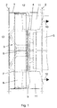
- the axial fan shown is used for ventilation of Structures and is for combined ventilation and Smoke extraction suitable.
- the axial fan contains a Housing 1, which is provided with two connecting flanges 2.
- In the housing 1 is an impeller 3 and a motor pot 4th arranged.
- the motor pot 4 takes a motor 5 for the drive of the impeller 3.
- the impeller 3 consists of a Motor 5 driven shaft 6, from a hub 7 and out in the Hub 7 arranged, preferably adjustable blades 8th.
- annular Flow channel 9 Between the housing 1 on the one hand and the motor pot 4 and the Hub 7 of the impeller 3, on the other hand, is annular Flow channel 9 through which the pumped medium in the direction of Arrows 10 is promoted. Downstream from the blades 8 are fixed guide vanes 11 in the flow channel 9 arranged.
- an insert ring 12 is used, which is on the inside of the Housing 1 is attached.
- This insert ring 12 consists of a material that is used in normal operation, i.e. for ventilation of rooms with promotion of indoor air, wear-resistant and at least briefly during a one-off Smoke extraction is heat-resistant.
- the distance of the peaks the blades 8 from the inner wall of the housing 1 0.2 to 2%, and the distance between the tips of the blades 8 from the inside of the insert ring 12 is 0.0 to 0.5% of the impeller diameter.
- the impeller gap is designed to be fluidly correct.
- the axial fan should remove smoke and fire gases from Promote elevated temperature.
- the material of the insert ring 12 is now chosen so that it is mechanical compared to the material the impeller 3 with mutual friction stress between Impeller 3 and insert ring 12 are wearing. Since that Impeller 3 under the influence of the elevated temperature of the Pumped medium expands and thereby increases in diameter now the tips of the blades 8 the insert ring 12 rub without coming into contact with the housing 1.
- the thickness of the insert ring 12 should be chosen so that the Never touch the blades 8 on the housing 1.
- FIGS. 4 and 5 The mode of operation of the insert ring 12 is shown in FIGS. 4 and 5 shown clearly.
- Fig. 4 the axial fan is in its original form, as it was for the Ventilation operation comes into question.
- Fig. 5 shows that the Diameter of the impeller 3 due to the increased The temperature of the hot smoke and combustion gases has increased.
- the Tips of the blades 8 have a part of the insert ring 12 rubbed, so that in turn an impeller gap of less Height between the impeller 3 and the now changed insert ring 12 exists.
- the front edge plane of the insert ring 12 is smooth and stands at an angle of 90 ° to the axis of the shaft 6 of the impeller 3.
- the insert ring 12 is the largest possible Bucket setting angle as flush as possible Impeller entry level 13 installed to ensure a flawless To ensure flow against the impeller 3. With smaller ones
- the blade leading angle is the front edge of the blade slightly above. If the insert ring 12 is not flush with Front edge of the blades 8 placed and is on the On the inflow side, in the event of a fire, it becomes the front Protruding area not sanded. This allows it to go through a bad flow against the expanded impeller 3 come to a stall. The impeller 3 then runs in one Bead that looks like a wheel gap that is too large. A little However, the insert ring 12 protrudes by a few mm harmless.
- the insert ring 12 extends at least over that of the Blades 8 coated area. He can also use the Trailing edge of the blades 8 out to the rear Edge of the hub 7 or reach up to the guide vanes 11.
- the Trailing edge of the insert ring 12 can be just like that Leading edge be smooth or tapered in diameter Run in housing 1.
- the material used for the insert ring 12 is flexible and consists preferably of fiber mats, which as webs to the Round shape of the housing 1 can be adjusted.
- the insert ring 12 can consist of one or more layers 14 one above the other be built, glued to the inner wall of the housing 1 or be fastened with the aid of rivets 15. These rivets 15 are in smoke extraction mode by the blades 8 rubbed together with the insert ring 12.
Landscapes
- Engineering & Computer Science (AREA)
- Mechanical Engineering (AREA)
- General Engineering & Computer Science (AREA)
- Structures Of Non-Positive Displacement Pumps (AREA)
- Cooling Or The Like Of Electrical Apparatus (AREA)
Abstract
Description
Claims (7)
- Axialventilator für Lüftungsanlagen für den kombinierten Lüftungs- und Entrauchungsbetrieb mit einem in einem Gehäuse (1) umlaufenden, mit Laufschaufeln (8) versehenen Laufrad (3), wobei zwischen den Spitzen der Laufschaufeln (8) und der Innenwand des Gehäuses (1) ein Laufradspalt besteht, dadurch gekennzeichnet, daß in dem Laufradspalt ein Einlegering (12) angeordnet ist, der an der Innenwand des Gehäuses (1) befestigt ist und daß der Einlegering (12) aus einem Werkstoff besteht, der im Lüftungsbetrieb im wesentlichen verschleißfrei und im Entrauchungsbetrieb verschleißend ist.
- Axialventilator nach Anspruch 1, dadurch gekennzeichnet, daß der Abstand der Spitzen der Laufschaufeln (8) von der Innenwand des Gehäuses (1) 0,2 bis 2 % und der Abstand der Spitzen der Laufschaufeln (8) von der Innenseite des Einlegeringes (12) 0,0 bis 0,5 % des Laufraddurchmessers beträgt.
- Axialventilator nach Anspruch 1 oder 2, dadurch gekennzeichnet, daß der Einlegering (12) mit der Anströmkante der Laufschaufeln (8) abschließt oder geringfügig über die Anströmkante vorsteht.
- Axialventilator nach einem der Ansprüche 1 bis 3, dadurch gekennzeichnet, daß die Einlegering (12) mindestens der Breite des von dem Laufrad (3) bestrichenen Bereiches entspricht.
- Axialventilator nach einem der Ansprüche 1 bis 4, dadurch gekennzeichnet, daß der Einlegering (12) über die Abströmkante der Laufschaufeln (8) hinausragt.
- Axialventilator nach einem der Ansprüche 1 bis 5, dadurch gekennzeichnet, daß der Einlegering (12) aus flexiblen Fasermatten besteht, die an die Innenwand des Gehäuses (1) angeformt und dort befestigt sind.
- Axialventilator nach einem der Ansprüche 1 bis 6, dadurch gekennzeichnet, daß der Einlegering (12) aus einem wärmebeständigen Werkstoff besteht.
Applications Claiming Priority (2)
| Application Number | Priority Date | Filing Date | Title |
|---|---|---|---|
| DE19755615A DE19755615A1 (de) | 1997-12-13 | 1997-12-13 | Axialventilator für Lüftungsanlagen |
| DE19755615 | 1997-12-13 |
Publications (3)
| Publication Number | Publication Date |
|---|---|
| EP0922862A2 true EP0922862A2 (de) | 1999-06-16 |
| EP0922862A3 EP0922862A3 (de) | 2000-04-12 |
| EP0922862B1 EP0922862B1 (de) | 2003-07-16 |
Family
ID=7851917
Family Applications (1)
| Application Number | Title | Priority Date | Filing Date |
|---|---|---|---|
| EP98122961A Expired - Lifetime EP0922862B1 (de) | 1997-12-13 | 1998-12-03 | Axialventilator für Lüftungsanlagen |
Country Status (3)
| Country | Link |
|---|---|
| EP (1) | EP0922862B1 (de) |
| AT (1) | ATE245255T1 (de) |
| DE (2) | DE19755615A1 (de) |
Families Citing this family (1)
| Publication number | Priority date | Publication date | Assignee | Title |
|---|---|---|---|---|
| DE202015104163U1 (de) | 2015-08-07 | 2016-11-10 | Systemair GmbH | Rotorflügel für einen Axialventilator |
Family Cites Families (4)
| Publication number | Priority date | Publication date | Assignee | Title |
|---|---|---|---|---|
| GB851267A (en) * | 1958-04-28 | 1960-10-12 | Gen Motors Corp | Improvements relating to axial-flow compressors |
| GB879740A (en) * | 1959-01-02 | 1961-10-11 | Axia Fans Ltd | Apparatus for expurging an enclosed space of gaseous media fouling the atmosphere therein |
| DE4423447A1 (de) * | 1994-07-05 | 1996-01-11 | Turbo Lufttechnik Gmbh | Axialventilator |
| DE4439726A1 (de) * | 1994-11-09 | 1996-05-15 | Siemens Ag | Laufrad für eine Strömungsmaschine |
-
1997
- 1997-12-13 DE DE19755615A patent/DE19755615A1/de not_active Withdrawn
-
1998
- 1998-12-03 DE DE59809019T patent/DE59809019D1/de not_active Expired - Lifetime
- 1998-12-03 AT AT98122961T patent/ATE245255T1/de active
- 1998-12-03 EP EP98122961A patent/EP0922862B1/de not_active Expired - Lifetime
Non-Patent Citations (1)
| Title |
|---|
| None |
Also Published As
| Publication number | Publication date |
|---|---|
| ATE245255T1 (de) | 2003-08-15 |
| DE19755615A1 (de) | 1999-06-17 |
| EP0922862A3 (de) | 2000-04-12 |
| EP0922862B1 (de) | 2003-07-16 |
| DE59809019D1 (de) | 2003-08-21 |
Similar Documents
| Publication | Publication Date | Title |
|---|---|---|
| DE60302589T2 (de) | Gebläsemotor | |
| EP1276994B1 (de) | Lüfter insbesondere zur belüftung von elektronischen geräten | |
| DE69102127T2 (de) | Lüfter, insbesondere für Kraftfahrzeuge. | |
| EP2211444B1 (de) | Elektromotor mit Kühlventilatorwirkung | |
| EP2802780B1 (de) | Axial- oder diagonallüfter mit stolperkante auf der laufschaufel-saugseite | |
| DE69228189T2 (de) | Ventilator mit vorwärtsgekrümmten schaufeln und angepasster schaufelkrümmung und -anstellung | |
| WO2004079201A1 (de) | Radiallüfterrad, lüftereinheit und radiallüfteranordnung | |
| DE2644066C2 (de) | Beschaufelung für eine Strömungsarbeitsmaschine | |
| DE2657840A1 (de) | Geraeuscharme kuehlanlage fuer brennkraftmaschinen | |
| DE102013101133A1 (de) | Gebläsebaugruppe | |
| DE102004018564A1 (de) | Zentrifugaler Gebläseventilator | |
| DE69105845T2 (de) | Staubsaugergebläse mit Laufrad. | |
| DE102008000168A1 (de) | Gebläseanordnung mit Vordrallerzeuger | |
| EP0304638B1 (de) | Gebläse | |
| DE102014012765A1 (de) | Radialverdichterstufe | |
| DE102014012764A1 (de) | Radialverdichterstufe | |
| EP1914402B1 (de) | Axialgebläse und Verfahren zur Verhinderung einer Rezirkulationsströmung | |
| DE112018002642T5 (de) | Gebläseeinheit einer Klimaanlage für ein Fahrzeug | |
| EP0515839B1 (de) | Laufrad für einen halbaxial wirkenden Lüfter | |
| EP2514347B1 (de) | Staubsauger-Turbobürste | |
| US20100092286A1 (en) | Axial flow fan | |
| DE20303443U1 (de) | Radiallüfterrad | |
| DE4113394C3 (de) | Ringkanalgebläse | |
| DE102011013677B4 (de) | Lüfterrad | |
| DE4130901A1 (de) | Geblaese |
Legal Events
| Date | Code | Title | Description |
|---|---|---|---|
| PUAI | Public reference made under article 153(3) epc to a published international application that has entered the european phase |
Free format text: ORIGINAL CODE: 0009012 |
|
| AK | Designated contracting states |
Kind code of ref document: A2 Designated state(s): AT CH DE LI NL SE |
|
| AX | Request for extension of the european patent |
Free format text: AL;LT;LV;MK;RO PAYMENT 19981203;SI PAYMENT 19981203 |
|
| PUAL | Search report despatched |
Free format text: ORIGINAL CODE: 0009013 |
|
| AK | Designated contracting states |
Kind code of ref document: A3 Designated state(s): AT BE CH CY DE DK ES FI FR GB GR IE IT LI LU MC NL PT SE |
|
| AX | Request for extension of the european patent |
Free format text: AL;LT;LV;MK;RO PAYMENT 19981203;SI PAYMENT 19981203 |
|
| RIC1 | Information provided on ipc code assigned before grant |
Free format text: 7F 04D 29/16 A, 7F 04D 19/00 B, 7F 04D 29/02 B |
|
| 17P | Request for examination filed |
Effective date: 20000509 |
|
| AKX | Designation fees paid |
Free format text: AT CH DE LI NL SE |
|
| AXX | Extension fees paid |
Free format text: RO PAYMENT 19981203;SI PAYMENT 19981203 |
|
| 17Q | First examination report despatched |
Effective date: 20020305 |
|
| GRAH | Despatch of communication of intention to grant a patent |
Free format text: ORIGINAL CODE: EPIDOS IGRA |
|
| GRAH | Despatch of communication of intention to grant a patent |
Free format text: ORIGINAL CODE: EPIDOS IGRA |
|
| GRAA | (expected) grant |
Free format text: ORIGINAL CODE: 0009210 |
|
| AK | Designated contracting states |
Designated state(s): AT CH DE LI NL SE |
|
| AX | Request for extension of the european patent |
Extension state: RO SI |
|
| PG25 | Lapsed in a contracting state [announced via postgrant information from national office to epo] |
Ref country code: NL Free format text: LAPSE BECAUSE OF FAILURE TO SUBMIT A TRANSLATION OF THE DESCRIPTION OR TO PAY THE FEE WITHIN THE PRESCRIBED TIME-LIMIT Effective date: 20030716 |
|
| REG | Reference to a national code |
Ref country code: CH Ref legal event code: EP |
|
| REF | Corresponds to: |
Ref document number: 59809019 Country of ref document: DE Date of ref document: 20030821 Kind code of ref document: P |
|
| RAP2 | Party data changed (patent owner data changed or rights of a patent transferred) |
Owner name: TLT-TURBO GMBH |
|
| PG25 | Lapsed in a contracting state [announced via postgrant information from national office to epo] |
Ref country code: SE Free format text: LAPSE BECAUSE OF FAILURE TO SUBMIT A TRANSLATION OF THE DESCRIPTION OR TO PAY THE FEE WITHIN THE PRESCRIBED TIME-LIMIT Effective date: 20031016 |
|
| NLT2 | Nl: modifications (of names), taken from the european patent patent bulletin |
Owner name: TLT-TURBO GMBH |
|
| NLV1 | Nl: lapsed or annulled due to failure to fulfill the requirements of art. 29p and 29m of the patents act | ||
| PLBE | No opposition filed within time limit |
Free format text: ORIGINAL CODE: 0009261 |
|
| STAA | Information on the status of an ep patent application or granted ep patent |
Free format text: STATUS: NO OPPOSITION FILED WITHIN TIME LIMIT |
|
| 26N | No opposition filed |
Effective date: 20040419 |
|
| REG | Reference to a national code |
Ref country code: CH Ref legal event code: PUE Owner name: TROX TLT GMBH, DE Free format text: FORMER OWNER: TLT-TURBO GMBH, DE Ref country code: CH Ref legal event code: NV Representative=s name: ALDO ROEMPLER PATENTANWALT, CH |
|
| REG | Reference to a national code |
Ref country code: DE Ref legal event code: R081 Ref document number: 59809019 Country of ref document: DE Owner name: TROX TLT GMBH, DE Free format text: FORMER OWNER: TLT-TURBO GMBH, 66482 ZWEIBRUECKEN, DE Effective date: 20130111 |
|
| REG | Reference to a national code |
Ref country code: AT Ref legal event code: PC Ref document number: 245255 Country of ref document: AT Kind code of ref document: T Owner name: TROX TLT GMBH, DE Effective date: 20130910 |
|
| PGFP | Annual fee paid to national office [announced via postgrant information from national office to epo] |
Ref country code: AT Payment date: 20171215 Year of fee payment: 20 Ref country code: CH Payment date: 20171221 Year of fee payment: 20 |
|
| PGFP | Annual fee paid to national office [announced via postgrant information from national office to epo] |
Ref country code: DE Payment date: 20171227 Year of fee payment: 20 |
|
| REG | Reference to a national code |
Ref country code: DE Ref legal event code: R071 Ref document number: 59809019 Country of ref document: DE |
|
| REG | Reference to a national code |
Ref country code: CH Ref legal event code: PL |
|
| REG | Reference to a national code |
Ref country code: AT Ref legal event code: MK07 Ref document number: 245255 Country of ref document: AT Kind code of ref document: T Effective date: 20181203 |