EP0922142B1 - Steel railroad sleepers - Google Patents
Steel railroad sleepers Download PDFInfo
- Publication number
- EP0922142B1 EP0922142B1 EP97937720A EP97937720A EP0922142B1 EP 0922142 B1 EP0922142 B1 EP 0922142B1 EP 97937720 A EP97937720 A EP 97937720A EP 97937720 A EP97937720 A EP 97937720A EP 0922142 B1 EP0922142 B1 EP 0922142B1
- Authority
- EP
- European Patent Office
- Prior art keywords
- sleeper
- end plate
- rail
- section
- clip
- Prior art date
- Legal status (The legal status is an assumption and is not a legal conclusion. Google has not performed a legal analysis and makes no representation as to the accuracy of the status listed.)
- Expired - Lifetime
Links
- 229910000831 Steel Inorganic materials 0.000 title claims description 22
- 239000010959 steel Substances 0.000 title claims description 22
- 241001669679 Eleotris Species 0.000 claims description 99
- 239000000463 material Substances 0.000 claims description 11
- 230000000295 complement effect Effects 0.000 claims description 6
- 229910000639 Spring steel Inorganic materials 0.000 claims description 3
- 238000003780 insertion Methods 0.000 claims description 3
- 230000037431 insertion Effects 0.000 claims description 3
- 239000012774 insulation material Substances 0.000 claims description 3
- 229920005830 Polyurethane Foam Polymers 0.000 claims description 2
- 239000011496 polyurethane foam Substances 0.000 claims description 2
- 238000000926 separation method Methods 0.000 claims description 2
- 239000012212 insulator Substances 0.000 description 4
- 238000004519 manufacturing process Methods 0.000 description 4
- 230000000694 effects Effects 0.000 description 3
- 238000009413 insulation Methods 0.000 description 3
- 230000007480 spreading Effects 0.000 description 3
- 238000003892 spreading Methods 0.000 description 3
- 239000004567 concrete Substances 0.000 description 2
- 229920001971 elastomer Polymers 0.000 description 2
- 238000010008 shearing Methods 0.000 description 2
- 229910001220 stainless steel Inorganic materials 0.000 description 2
- 229910000922 High-strength low-alloy steel Inorganic materials 0.000 description 1
- 239000004793 Polystyrene Substances 0.000 description 1
- 230000008901 benefit Effects 0.000 description 1
- 239000004568 cement Substances 0.000 description 1
- 238000000576 coating method Methods 0.000 description 1
- 238000007596 consolidation process Methods 0.000 description 1
- 230000007797 corrosion Effects 0.000 description 1
- 238000005260 corrosion Methods 0.000 description 1
- 230000001419 dependent effect Effects 0.000 description 1
- 239000000806 elastomer Substances 0.000 description 1
- 238000005538 encapsulation Methods 0.000 description 1
- 239000006260 foam Substances 0.000 description 1
- 238000009434 installation Methods 0.000 description 1
- 239000011810 insulating material Substances 0.000 description 1
- 238000000034 method Methods 0.000 description 1
- 239000000203 mixture Substances 0.000 description 1
- 238000012986 modification Methods 0.000 description 1
- 230000004048 modification Effects 0.000 description 1
- 238000000465 moulding Methods 0.000 description 1
- 229920003023 plastic Polymers 0.000 description 1
- 229920002223 polystyrene Polymers 0.000 description 1
- 239000011150 reinforced concrete Substances 0.000 description 1
- 239000002990 reinforced plastic Substances 0.000 description 1
- 238000009877 rendering Methods 0.000 description 1
- 230000000452 restraining effect Effects 0.000 description 1
- 238000005480 shot peening Methods 0.000 description 1
- 239000007787 solid Substances 0.000 description 1
- 239000010935 stainless steel Substances 0.000 description 1
- XLYOFNOQVPJJNP-UHFFFAOYSA-N water Substances O XLYOFNOQVPJJNP-UHFFFAOYSA-N 0.000 description 1
- 238000003466 welding Methods 0.000 description 1
Images

Classifications
-
- E—FIXED CONSTRUCTIONS
- E01—CONSTRUCTION OF ROADS, RAILWAYS, OR BRIDGES
- E01B—PERMANENT WAY; PERMANENT-WAY TOOLS; MACHINES FOR MAKING RAILWAYS OF ALL KINDS
- E01B3/00—Transverse or longitudinal sleepers; Other means resting directly on the ballastway for supporting rails
- E01B3/16—Transverse or longitudinal sleepers; Other means resting directly on the ballastway for supporting rails made from steel
Definitions
- This invention relates to steel railroad or railway sleepers and to methods of producing such sleepers.
- Sleepers are integral parts of flexible support systems used for guiding trains. Their key functions are to retain the gauge and inclination of the rails which they support and to assist to maintain both lateral and vertical tolerances placed on the track. They also transmit loads to a supporting bed of ballast over a surface area which is significantly greater than that applied by a wheel of a train and are required to do so in such a manner as to enable the ballast to spread the transmitted load onto the subsoil below the ballast bed without deformation of that subsoil. Sleepers are required to maintain rail track stability during the passage of trains and to maintain this stability notwithstanding temperature changes, this latter feature being more important when continuously welded track is employed.
- a minor proportion of sleepers currently employed are produced from steel, these providing lower installation costs than more conventional sleepers of concrete or timber.
- Steel sleepers are generally of box or inverted channel section and are relatively easy to transport having a higher stacking density, require less expensive equipment to instal, have no need for re-ballasting and require less ballast depth because of their shape. Their use results in shorter and predictable track possession times, and their relatively light weight makes them easier to handle and instal than the more conventional solid concrete or timber sleepers. Also, they are less susceptible to gauge spread and derailment damage and can be repaired; they also have a scrap value.
- steel sleepered track is more difficult to move during realignment schemes.
- a steel box-section sleeper is disclosed by DE-A-2951272.
- the open ends of this sleeper are closed by welded steel plates or mouldings of reinforced concrete or plastics.
- the hollow interior of the box-section is filled with an insulating material, for example a mix of cement and water or a rubber elastomer.
- GB-A-9351 discloses a combination of a steel railroad sleeper of inverted channel section and end plates for selectively closing the open ends of the sleeper.
- the sides of the sleeper are inclined downwardly and outwardly from an upper rail supporting surface.
- the sleeper is produced by cold forming steel.
- WO 89/10450 discloses a steel railroad sleeper of inverted channel section which includes restraining elements attached to and dependent from the underside of the upper supporting surface of the sleeper. These elements include downwardly oriented branches which, in use of the sleeper, provide lateral stability for the sleeper.
- the present invention sets out to provide a sleeper which overcomes, or at least alleviates, some of the disadvantages referred to above.
- a steel railroad sleeper produced by cold forming steel strip and including an open-ended elongate body of inverted channel section having side walls which incline downwardly and outwardly from an upper rail supporting surface and two substantially vertical end plates for closing the substantially vertical open ends of the sleeper body, the sleeper being characterised in that each end of the edge of the sleeper body and each side edge of each end plate includes complementary connection means whereby each end plate can selectively be removed from or attached to the open ends of the sleeper body by effecting a vertically downward sliding movement of the respective end plate with respect to the sleeper body to disengage or engage respectively the complementary connection means, the depth of each end plate being greater than that of the sleeper body such that, in use, each end plate extends downwardly a greater distance than the side walls of the sleeper body.
- the end plates may also be produced by cold forming steel strip.
- the sleeper and/or end plates may be produced from mild or stainless or HSLA steel. If produced from stainless steel, shot peening or anticorrosion coatings may be effected or provided, to counter any stress corrosion.
- each side of the sleeper may be turned outwardly and upwardly to define a lip.
- each end plate An opening may be provided in the top of each end plate through which ballast can pass.
- the sleeper may be formed at or adjacent one or each end with an opening through which ballast can pass.
- the sleeper may have a waisted section of reduced width. This waisted section may be positioned generally midway along the length of the sleeper.
- the central section of the sleeper interior may be filled with a material to prevent the ingress of ballast to this central region.
- the material may be a sound deadening material and may comprise expanded polyurethane foam.
- the internal walls of the sleeper may be at least partially coated with a sound deadening material.
- the invention also provides a railroad sleeper as described above in combination with a spring steel clip which secures the rail directly to the sleeper.
- the clip includes a first bearing surface for engagement with the upper surface of the sleeper, a second bearing surface for engagement with the underside of the rail supporting surface of the sleeper, and a loop section intermediate the first and second bearing surfaces which, in use, engages the upper surface of a foot flange of the rail, and the tool including means for applying a force to the internal surfaces of the loop section of the clip to increase the separation thereof whereby the required engagement of the bearing surfaces with the rail and the loop section of the clip with the rail flange is facilitated after the insertion of insulation material between the opposed surfaces of the loop and the rail flange and relaxation of the force applied by the tool.
- the insulation material is preferably preformed to complement the upper surface of the rail flange.
- the clip may be generally "U” shaped in plan with the central section of the "U” defining the first mentioned bearing surface and with each leg of the "U” defining second bearing surfaces and a loop section.
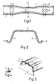
- the illustrated sleeper 1 when in use is of inverted channel section and is open-ended.
- the sides 2 of the sleeper are inclined downwardly and outwardly to provide the necessary face angle to establish the required stability and resistance to vertical pull-out.
- the face angle is also selected to increase stackability density without creating friction which would lead to sticking of neighbouring stacked sleepers.
- the depth of each side is greater than with more traditional hot rolled products to increase ballast encapsulation.
- Each longitudinal side of the sleeper is turned outwardly and upwardly to define a lip 3 to increase stiffness and vertical pull-out resistance.
- the open ends of the sleeper are closed by separable substantially vertical end plates 4 which are detachably secured to the sleeper through locating lugs 5 formed on each side of each end plate which interlock with locking tabs 6 formed along each end edge of the sleeper.
- Assembly of the end plates to the sleeper is accomplished either automatically or by using a special hand tool.
- the end plates can, therefore, only be removed by using special tooling, thereby rendering them tamper-proof.
- Openings 7 are formed in the end plates or in the sleeper ends to enable ballast to be injected into the sleeper interior. As shown, these openings comprise slots formed in the free edges of the upper rail supporting surface of the sleeper.
- the sleeper has a central section 8 which is waisted. This waisting creates greater locking of ballast propelled into the sleeper interior and reduces the amount of ballast necessary to fill the sleeper interior.
- Sound deadening material may be applied to some or all internal surfaces of the sleeper and similar material may be positioned within the central section 8 not only to deaden sound but also to prevent the ingress of ballast into this central rail section.
- One suitable material is an expanded foam of, for example, polystyrene.
- Holes 9 are stamped into the upper surface of the sleeper to receive attachment clips for securing rails to the sleeper. These will be described below with reference to Figures 5 to 8. The positions of rails to be supported by the sleeper are shown in chain dotted lines 10.
- each end plate 4 extends downwardly a greater distance than the side walls 2 of the sleeper thereby improving lateral stability and reducing shoulder ballast while permitting ready realignment of the sleeper simply by removing the end plates.
- the inverted channel section of the sleeper is produced by cold forming steel strip.
- strip from a down coiler is passed through a leveller before shearing to size for cold forming.
- Sleepers may be so formed individually or as multiples, either in the longitudinal or transverse direction of the strip.
- Material discarded during shearing may be passed to a secondary forming press for the production of the end plates 4.
- the end plates may be produced by cold forming suitable shaped steel strips.
- the end lugs 5 and tabs 6 are produced by special tooling and supplementary operations.
- each sleeper When installing sleepers in accordance with the invention on a prepared ballast bed, each sleeper can, because of its shape and open-ends, simply be slid into place. Accurate placement of the sleepers can, therefore, be more readily achieved.
- sleepers with end plates already fitted can be placed conventionally on a suitable spread ballast bed.
- ballast Prior to fitting the end plates to the sleeper, ballast can be blown into the sleeper through its open ends at the optimum pressure to fill all cavities under the inclined regions of the sleeper. This avoids the need for extra tamping required for traditional steel sleepers. As a consequence, ballast life is enhanced, damage from tamping being avoided. If the end plates 4 are already installed, ballast can be blown into the sleeper interior through the openings 7.
- holes 9 are stamped in the upper surface of the sleeper 1 to receive attachment clips to secure the rails 10 to the sleeper.
- the sleeper may be shot peened in the vicinity of the holes 9 to enhance the residual stress pattern and integrity. This arrangement enhances the benefit of sliding sleepers into place because all protrusions are eliminated.
- the attachment clip shown in Figures 5 and 6 takes the form of a clip manufactured from a spring steel of rectangular cross-section. Other cross-sections such as circular or oval may be adopted.
- the fastening is generally of "U" shape and comprises a pair of arms 14 joined to a central section 15 set generally normal to the arms.
- each arm of the clip is shaped to include sequentially from its free end a shoulder 16 which extends in the direction towards the central section 15, a leg 17 generally normal to the shoulder 16, a loop 18 having a neck 19 and a curved section 20 which leads to the central section 15.
- a spreading tool is insertable within the neck 19 and is operable to increase the neck width and to effect elongation of the leg 17.
- a rail 10 supported on the sleeper 1 is also illustrated in Figure 6.
- a preformed insulator 21 is positioned on the foot flange of the rail 10.
- the rail seats on a conventional insulation pad 22.
- the spreading tool On assembly of the clip to the rail and the sleeper, the spreading tool is then inserted into the neck 19 and operated to increase the neck width and effect elongation of the leg thereby increasing the spacing between the loop and the rail flange.
- the free end of each arm 14 of the clip is then passed through the respective hole 9 and the clip is moved to the position shown in Figure 6 in which the shoulder 16 engages the under surface of the sleeper with the leg 17 contacting the hole boundary. In this position the central section 15 of the clip bears against the upper surface of the sleeper and the loop 18 is positioned above the rail flange (the preformed insulator 21 not being present at this time). With the spreader in place the preformed insulator 21 is inserted between the clip and the rail flange.
- the rail 10 is bonded through a combined layer of bonding material insulation 25 within a shallow recess formed in the sleeper upper surface.
- the rail 10 is supported within and secured to a spring clip 27 which in turn is bonded to the sleeper surface, possibly within a recess similar to recess illustrated in Figure 7.
- the clip may be bolted, welded or bonded to the sleeper, an insulation pad 28 being positioned between the opposed surfaces of the rail flange and the clip.
Landscapes
- Engineering & Computer Science (AREA)
- Architecture (AREA)
- Civil Engineering (AREA)
- Structural Engineering (AREA)
- Railway Tracks (AREA)
- Machines For Laying And Maintaining Railways (AREA)
- Bridges Or Land Bridges (AREA)
- Road Paving Structures (AREA)
Applications Claiming Priority (3)
| Application Number | Priority Date | Filing Date | Title |
|---|---|---|---|
| GBGB9617918.9A GB9617918D0 (en) | 1996-08-28 | 1996-08-28 | Railway sleepers |
| GB9617918 | 1996-08-28 | ||
| PCT/GB1997/002292 WO1998009022A1 (en) | 1996-08-28 | 1997-08-27 | Steel railroad sleepers |
Publications (2)
| Publication Number | Publication Date |
|---|---|
| EP0922142A1 EP0922142A1 (en) | 1999-06-16 |
| EP0922142B1 true EP0922142B1 (en) | 2002-10-16 |
Family
ID=10799018
Family Applications (1)
| Application Number | Title | Priority Date | Filing Date |
|---|---|---|---|
| EP97937720A Expired - Lifetime EP0922142B1 (en) | 1996-08-28 | 1997-08-27 | Steel railroad sleepers |
Country Status (22)
| Country | Link |
|---|---|
| US (1) | US6230981B1 (enExample) |
| EP (1) | EP0922142B1 (enExample) |
| JP (1) | JP2001504905A (enExample) |
| CN (1) | CN1112479C (enExample) |
| AP (1) | AP1087A (enExample) |
| AT (1) | ATE226270T1 (enExample) |
| AU (1) | AU739411B2 (enExample) |
| BR (1) | BR9711389A (enExample) |
| CA (1) | CA2264727A1 (enExample) |
| CZ (1) | CZ294026B6 (enExample) |
| DE (1) | DE69716446T2 (enExample) |
| GB (1) | GB9617918D0 (enExample) |
| GE (1) | GEP20032978B (enExample) |
| IL (1) | IL128748A (enExample) |
| NZ (1) | NZ334493A (enExample) |
| OA (1) | OA11104A (enExample) |
| PL (1) | PL187877B1 (enExample) |
| RO (1) | RO119025B1 (enExample) |
| SI (1) | SI9720056B (enExample) |
| SK (1) | SK27399A3 (enExample) |
| UA (1) | UA66347C2 (enExample) |
| WO (1) | WO1998009022A1 (enExample) |
Cited By (1)
| Publication number | Priority date | Publication date | Assignee | Title |
|---|---|---|---|---|
| DE102007031705A1 (de) | 2007-07-06 | 2009-01-08 | Thyssenkrupp Gft Gleistechnik Gmbh | Schwelle für feste Fahrbahnen |
Families Citing this family (25)
| Publication number | Priority date | Publication date | Assignee | Title |
|---|---|---|---|---|
| GB2383066A (en) * | 2001-12-11 | 2003-06-18 | Corus Uk Ltd | Steel sleeper assembly |
| GB2389867B (en) * | 2002-06-21 | 2005-11-09 | Corus Uk Ltd | Steel railway sleepers |
| GB2394244A (en) * | 2002-10-10 | 2004-04-21 | Corus Uk Ltd | Hollow steel railway sleeper |
| JP2006520828A (ja) * | 2003-03-21 | 2006-09-14 | フォ デルマ インコーポレイテッド | 光応答芳香物 |
| DE10319055B4 (de) * | 2003-04-25 | 2006-03-02 | Ferd. Braselmann Gmbh & Co. Kg | Verfahren zur Herstellung von Stahlschwellen sowie Stahlschwelle |
| CA2499193C (en) * | 2005-03-23 | 2007-01-02 | Tembec Industries Inc. | Railway ground crosstie |
| US7731099B2 (en) * | 2005-10-25 | 2010-06-08 | Narstco, Inc. | Stacked railway tie |
| US8714462B1 (en) | 2008-07-09 | 2014-05-06 | Polycorp Ltd. | Special track assembly and methods of making same |
| US9346237B2 (en) | 2010-10-27 | 2016-05-24 | Richard W. Roberts | Recyclable plastic structural articles and method of manufacture |
| US8342420B2 (en) * | 2010-10-27 | 2013-01-01 | Roberts Jr Richard W | Recyclable plastic structural articles and method of manufacture |
| US20130115399A1 (en) | 2010-10-27 | 2013-05-09 | Richard W. Roberts | In-situ foam core articles |
| JP5918764B2 (ja) * | 2011-06-20 | 2016-05-18 | 日鐵住金建材株式会社 | 冷間成形鋼製枕木 |
| US9272484B2 (en) | 2012-01-25 | 2016-03-01 | Richard W. Roberts, JR. | Structural plastic articles, method of use, and methods of manufacture |
| US9102086B2 (en) | 2012-03-28 | 2015-08-11 | Richard W. Roberts | In-situ foam core structural articles and methods of manufacture of profiles |
| US8840819B2 (en) | 2012-03-28 | 2014-09-23 | Richard W. Roberts, JR. | In-situ foam core structural energy management system and method of manufacture |
| US10207606B2 (en) | 2012-03-28 | 2019-02-19 | Richard W. Roberts | Recyclable plastic structural articles and method of manufacture |
| US9073462B2 (en) | 2012-03-28 | 2015-07-07 | Richard W. Roberts | In-situ foam core vehicle seating system and method of manufacture |
| US8708177B2 (en) | 2012-03-29 | 2014-04-29 | Richard W. Roberts | In-situ foam core dielectrically-resistant systems and method of manufacture |
| GB2502542B (en) * | 2012-05-30 | 2019-10-23 | Sigassure Uk Ltd | Hollow sleepers and cable management system |
| US10328662B2 (en) | 2012-11-01 | 2019-06-25 | Richard W. Roberts | In-situ foam core stress mitigation component and method of manufacture |
| US9271610B2 (en) | 2013-04-12 | 2016-03-01 | Richard W. Roberts, JR. | Bathtub/shower tray support |
| US9644323B2 (en) * | 2014-04-15 | 2017-05-09 | Keith A. Langenbeck | Train rail track structure systems |
| US9617688B2 (en) | 2014-06-26 | 2017-04-11 | Polycorp Ltd. | Rail assembly |
| US9695553B2 (en) * | 2014-09-23 | 2017-07-04 | Claude R Kendrick, Jr. | Modular railroad track assembly |
| CN105507089A (zh) * | 2015-11-30 | 2016-04-20 | 无锡市恒达矿山机械有限公司 | 一种矿山使用的专用枕 |
Family Cites Families (7)
| Publication number | Priority date | Publication date | Assignee | Title |
|---|---|---|---|---|
| BE388815A (enExample) * | ||||
| GB191009351A (en) * | 1910-04-18 | 1910-09-08 | Ross Albert Finley | Improvements in and relating to Metallic Railroad Ties. |
| GB333761A (en) * | 1929-09-02 | 1930-08-21 | Thomas Hugh Davies | Improvements in railway or the like sleepers |
| US2841338A (en) * | 1955-09-16 | 1958-07-01 | William H Fairbert | Railroad tie |
| JPS586705A (ja) * | 1981-07-01 | 1983-01-14 | Kawasaki Steel Corp | 形鋼の圧延方法 |
| JPS63108920A (ja) * | 1986-10-27 | 1988-05-13 | Nippon Steel Corp | 有爪鋼製枕木の製造方法 |
| AU685812B2 (en) * | 1993-06-02 | 1998-01-29 | Jude Odihachukwunma Igwemezie | Improved rail tie, tie plate and clip |
-
1996
- 1996-08-28 GB GBGB9617918.9A patent/GB9617918D0/en active Pending
-
1997
- 1997-08-27 IL IL12874897A patent/IL128748A/xx not_active IP Right Cessation
- 1997-08-27 US US09/147,732 patent/US6230981B1/en not_active Expired - Fee Related
- 1997-08-27 EP EP97937720A patent/EP0922142B1/en not_active Expired - Lifetime
- 1997-08-27 JP JP51137698A patent/JP2001504905A/ja not_active Ceased
- 1997-08-27 AT AT97937720T patent/ATE226270T1/de not_active IP Right Cessation
- 1997-08-27 PL PL33189497A patent/PL187877B1/pl not_active IP Right Cessation
- 1997-08-27 RO RO99-00222A patent/RO119025B1/ro unknown
- 1997-08-27 NZ NZ334493A patent/NZ334493A/xx unknown
- 1997-08-27 CZ CZ1999687A patent/CZ294026B6/cs not_active IP Right Cessation
- 1997-08-27 GE GEAP19974725A patent/GEP20032978B/en unknown
- 1997-08-27 CN CN97198346A patent/CN1112479C/zh not_active Expired - Fee Related
- 1997-08-27 WO PCT/GB1997/002292 patent/WO1998009022A1/en not_active Ceased
- 1997-08-27 SI SI9720056A patent/SI9720056B/sl not_active IP Right Cessation
- 1997-08-27 SK SK273-99A patent/SK27399A3/sk unknown
- 1997-08-27 AP APAP/P/1999/001475A patent/AP1087A/en active
- 1997-08-27 UA UA99031715A patent/UA66347C2/uk unknown
- 1997-08-27 CA CA002264727A patent/CA2264727A1/en not_active Abandoned
- 1997-08-27 DE DE69716446T patent/DE69716446T2/de not_active Expired - Fee Related
- 1997-08-27 BR BR9711389A patent/BR9711389A/pt not_active IP Right Cessation
- 1997-08-27 AU AU40252/97A patent/AU739411B2/en not_active Ceased
-
1999
- 1999-02-26 OA OA9900044A patent/OA11104A/en unknown
Cited By (1)
| Publication number | Priority date | Publication date | Assignee | Title |
|---|---|---|---|---|
| DE102007031705A1 (de) | 2007-07-06 | 2009-01-08 | Thyssenkrupp Gft Gleistechnik Gmbh | Schwelle für feste Fahrbahnen |
Also Published As
| Publication number | Publication date |
|---|---|
| NZ334493A (en) | 1999-08-30 |
| DE69716446D1 (de) | 2002-11-21 |
| GB9617918D0 (en) | 1996-10-09 |
| WO1998009022A1 (en) | 1998-03-05 |
| OA11104A (en) | 2003-03-17 |
| CZ294026B6 (cs) | 2004-09-15 |
| RO119025B1 (ro) | 2004-02-27 |
| UA66347C2 (en) | 2004-05-17 |
| SI9720056A (sl) | 1999-06-30 |
| AP9901475A0 (en) | 1999-03-31 |
| BR9711389A (pt) | 1999-08-17 |
| AU739411B2 (en) | 2001-10-11 |
| PL331894A1 (en) | 1999-08-16 |
| US6230981B1 (en) | 2001-05-15 |
| EP0922142A1 (en) | 1999-06-16 |
| DE69716446T2 (de) | 2003-06-18 |
| PL187877B1 (pl) | 2004-10-29 |
| AU4025297A (en) | 1998-03-19 |
| SK27399A3 (en) | 1999-10-08 |
| JP2001504905A (ja) | 2001-04-10 |
| IL128748A (en) | 2001-08-26 |
| AP1087A (en) | 2002-08-01 |
| CA2264727A1 (en) | 1998-03-05 |
| CN1231709A (zh) | 1999-10-13 |
| SI9720056B (sl) | 2002-02-28 |
| CN1112479C (zh) | 2003-06-25 |
| CZ68799A3 (cs) | 1999-06-16 |
| ATE226270T1 (de) | 2002-11-15 |
| GEP20032978B (en) | 2003-05-27 |
| IL128748A0 (en) | 2000-01-31 |
Similar Documents
| Publication | Publication Date | Title |
|---|---|---|
| EP0922142B1 (en) | Steel railroad sleepers | |
| US4899933A (en) | Railway crossing insert | |
| MXPA00011902A (es) | Riel de ferrocarril o tranvia y sistema de fijacion de riel. | |
| SG191362A1 (en) | Method for producing a slab trackway | |
| US11313084B2 (en) | Device for forming a level crossing | |
| GB2298442A (en) | Railway rail fastening clip and assembly | |
| US6517008B1 (en) | Boltless adjustable rail brace assembly with external vertical restraint | |
| KR101807079B1 (ko) | 고무보판 철도 건널목 장치 | |
| US8752773B2 (en) | Grade crossing interface pad | |
| US10458071B2 (en) | Method of installing interface pad on concrete ties | |
| US6568601B2 (en) | Boltless adjustable rail brace assembly with internal vertical restraint | |
| OA11804A (en) | Preloading rail clips in steel sleepers. | |
| CN211079786U (zh) | 钢轨临时固定结构 | |
| US1008868A (en) | Metallic tie and rail-fastener. | |
| KR20000049299A (ko) | 급곡선과 열차의 탈선이 우려되는 개소의 안전가드앵글 체결장치 | |
| US935966A (en) | Railway-tie. | |
| CA1280729C (en) | Railway crossing insert | |
| US924705A (en) | Railway cross-tie. | |
| JPH076163B2 (ja) | 踏切構造 | |
| CA2162349A1 (en) | Rail fastener devices | |
| AU1364400A (en) | Improved elastic rail fastener | |
| HK1055770A1 (en) | Concrete work construction method and use thereof in railway, subway or tramway tracks | |
| JPH0618403U (ja) | 有道床軌道における枕木の挫屈防止板付き防振装置 |
Legal Events
| Date | Code | Title | Description |
|---|---|---|---|
| PUAI | Public reference made under article 153(3) epc to a published international application that has entered the european phase |
Free format text: ORIGINAL CODE: 0009012 |
|
| 17P | Request for examination filed |
Effective date: 19990317 |
|
| AK | Designated contracting states |
Kind code of ref document: A1 Designated state(s): AT BE CH DE DK ES FI FR GB GR IE IT LI LU MC NL PT SE |
|
| RAP1 | Party data changed (applicant data changed or rights of an application transferred) |
Owner name: BRITISH STEEL LIMITED |
|
| RAP1 | Party data changed (applicant data changed or rights of an application transferred) |
Owner name: BRITISH STEEL LIMITED |
|
| RAP1 | Party data changed (applicant data changed or rights of an application transferred) |
Owner name: CORUS UK LIMITED |
|
| 17Q | First examination report despatched |
Effective date: 20010216 |
|
| GRAG | Despatch of communication of intention to grant |
Free format text: ORIGINAL CODE: EPIDOS AGRA |
|
| GRAG | Despatch of communication of intention to grant |
Free format text: ORIGINAL CODE: EPIDOS AGRA |
|
| GRAH | Despatch of communication of intention to grant a patent |
Free format text: ORIGINAL CODE: EPIDOS IGRA |
|
| RAP1 | Party data changed (applicant data changed or rights of an application transferred) |
Owner name: CORUS UK LIMITED |
|
| GRAH | Despatch of communication of intention to grant a patent |
Free format text: ORIGINAL CODE: EPIDOS IGRA |
|
| GRAA | (expected) grant |
Free format text: ORIGINAL CODE: 0009210 |
|
| AK | Designated contracting states |
Kind code of ref document: B1 Designated state(s): AT BE CH DE DK ES FI FR GB GR IE IT LI LU MC NL PT SE |
|
| PG25 | Lapsed in a contracting state [announced via postgrant information from national office to epo] |
Ref country code: NL Free format text: LAPSE BECAUSE OF FAILURE TO SUBMIT A TRANSLATION OF THE DESCRIPTION OR TO PAY THE FEE WITHIN THE PRESCRIBED TIME-LIMIT Effective date: 20021016 Ref country code: IT Free format text: LAPSE BECAUSE OF FAILURE TO SUBMIT A TRANSLATION OF THE DESCRIPTION OR TO PAY THE FEE WITHIN THE PRE;WARNING: LAPSES OF ITALIAN PATENTS WITH EFFECTIVE DATE BEFORE 2007 MAY HAVE OCCURRED AT ANY TIME BEFORE 2007. THE CORRECT EFFECTIVE DATE MAY BE DIFFERENT FROM THE ONE RECORDED.SCRIBED TIME-LIMIT Effective date: 20021016 Ref country code: FI Free format text: LAPSE BECAUSE OF FAILURE TO SUBMIT A TRANSLATION OF THE DESCRIPTION OR TO PAY THE FEE WITHIN THE PRESCRIBED TIME-LIMIT Effective date: 20021016 Ref country code: AT Free format text: LAPSE BECAUSE OF FAILURE TO SUBMIT A TRANSLATION OF THE DESCRIPTION OR TO PAY THE FEE WITHIN THE PRESCRIBED TIME-LIMIT Effective date: 20021016 |
|
| REF | Corresponds to: |
Ref document number: 226270 Country of ref document: AT Date of ref document: 20021115 Kind code of ref document: T |
|
| REG | Reference to a national code |
Ref country code: GB Ref legal event code: FG4D |
|
| REG | Reference to a national code |
Ref country code: CH Ref legal event code: EP |
|
| REG | Reference to a national code |
Ref country code: IE Ref legal event code: FG4D |
|
| REF | Corresponds to: |
Ref document number: 69716446 Country of ref document: DE Date of ref document: 20021121 |
|
| PG25 | Lapsed in a contracting state [announced via postgrant information from national office to epo] |
Ref country code: PT Free format text: LAPSE BECAUSE OF FAILURE TO SUBMIT A TRANSLATION OF THE DESCRIPTION OR TO PAY THE FEE WITHIN THE PRESCRIBED TIME-LIMIT Effective date: 20030116 Ref country code: DK Free format text: LAPSE BECAUSE OF FAILURE TO SUBMIT A TRANSLATION OF THE DESCRIPTION OR TO PAY THE FEE WITHIN THE PRESCRIBED TIME-LIMIT Effective date: 20030116 |
|
| REG | Reference to a national code |
Ref country code: GR Ref legal event code: EP Ref document number: 20030400186 Country of ref document: GR |
|
| NLV1 | Nl: lapsed or annulled due to failure to fulfill the requirements of art. 29p and 29m of the patents act | ||
| PG25 | Lapsed in a contracting state [announced via postgrant information from national office to epo] |
Ref country code: ES Free format text: LAPSE BECAUSE OF FAILURE TO SUBMIT A TRANSLATION OF THE DESCRIPTION OR TO PAY THE FEE WITHIN THE PRESCRIBED TIME-LIMIT Effective date: 20030429 |
|
| ET | Fr: translation filed | ||
| PGFP | Annual fee paid to national office [announced via postgrant information from national office to epo] |
Ref country code: GR Payment date: 20030711 Year of fee payment: 7 |
|
| PGFP | Annual fee paid to national office [announced via postgrant information from national office to epo] |
Ref country code: SE Payment date: 20030728 Year of fee payment: 7 |
|
| PLBE | No opposition filed within time limit |
Free format text: ORIGINAL CODE: 0009261 |
|
| STAA | Information on the status of an ep patent application or granted ep patent |
Free format text: STATUS: NO OPPOSITION FILED WITHIN TIME LIMIT |
|
| PG25 | Lapsed in a contracting state [announced via postgrant information from national office to epo] |
Ref country code: LU Free format text: LAPSE BECAUSE OF NON-PAYMENT OF DUE FEES Effective date: 20030827 |
|
| PG25 | Lapsed in a contracting state [announced via postgrant information from national office to epo] |
Ref country code: MC Free format text: LAPSE BECAUSE OF NON-PAYMENT OF DUE FEES Effective date: 20030831 |
|
| 26N | No opposition filed |
Effective date: 20030717 |
|
| PG25 | Lapsed in a contracting state [announced via postgrant information from national office to epo] |
Ref country code: SE Free format text: LAPSE BECAUSE OF NON-PAYMENT OF DUE FEES Effective date: 20040828 |
|
| PG25 | Lapsed in a contracting state [announced via postgrant information from national office to epo] |
Ref country code: GR Free format text: LAPSE BECAUSE OF NON-PAYMENT OF DUE FEES Effective date: 20050303 |
|
| EUG | Se: european patent has lapsed | ||
| PGFP | Annual fee paid to national office [announced via postgrant information from national office to epo] |
Ref country code: IE Payment date: 20050706 Year of fee payment: 9 |
|
| PGFP | Annual fee paid to national office [announced via postgrant information from national office to epo] |
Ref country code: GB Payment date: 20050728 Year of fee payment: 9 |
|
| PGFP | Annual fee paid to national office [announced via postgrant information from national office to epo] |
Ref country code: FR Payment date: 20050812 Year of fee payment: 9 Ref country code: CH Payment date: 20050812 Year of fee payment: 9 |
|
| PGFP | Annual fee paid to national office [announced via postgrant information from national office to epo] |
Ref country code: BE Payment date: 20050914 Year of fee payment: 9 |
|
| PGFP | Annual fee paid to national office [announced via postgrant information from national office to epo] |
Ref country code: DE Payment date: 20051031 Year of fee payment: 9 |
|
| PG25 | Lapsed in a contracting state [announced via postgrant information from national office to epo] |
Ref country code: IE Free format text: LAPSE BECAUSE OF NON-PAYMENT OF DUE FEES Effective date: 20060828 |
|
| PG25 | Lapsed in a contracting state [announced via postgrant information from national office to epo] |
Ref country code: LI Free format text: LAPSE BECAUSE OF NON-PAYMENT OF DUE FEES Effective date: 20060831 Ref country code: CH Free format text: LAPSE BECAUSE OF NON-PAYMENT OF DUE FEES Effective date: 20060831 Ref country code: BE Free format text: LAPSE BECAUSE OF NON-PAYMENT OF DUE FEES Effective date: 20060831 |
|
| PG25 | Lapsed in a contracting state [announced via postgrant information from national office to epo] |
Ref country code: DE Free format text: LAPSE BECAUSE OF NON-PAYMENT OF DUE FEES Effective date: 20070301 |
|
| REG | Reference to a national code |
Ref country code: CH Ref legal event code: PL |
|
| GBPC | Gb: european patent ceased through non-payment of renewal fee |
Effective date: 20060827 |
|
| REG | Reference to a national code |
Ref country code: IE Ref legal event code: MM4A |
|
| REG | Reference to a national code |
Ref country code: FR Ref legal event code: ST Effective date: 20070430 |
|
| PG25 | Lapsed in a contracting state [announced via postgrant information from national office to epo] |
Ref country code: GB Free format text: LAPSE BECAUSE OF NON-PAYMENT OF DUE FEES Effective date: 20060827 |
|
| BERE | Be: lapsed |
Owner name: *CORUS UK LTD Effective date: 20060831 |
|
| PG25 | Lapsed in a contracting state [announced via postgrant information from national office to epo] |
Ref country code: FR Free format text: LAPSE BECAUSE OF NON-PAYMENT OF DUE FEES Effective date: 20060831 |