EP0921968B1 - Scheibenwischvorrichtung - Google Patents
Scheibenwischvorrichtung Download PDFInfo
- Publication number
- EP0921968B1 EP0921968B1 EP97934553A EP97934553A EP0921968B1 EP 0921968 B1 EP0921968 B1 EP 0921968B1 EP 97934553 A EP97934553 A EP 97934553A EP 97934553 A EP97934553 A EP 97934553A EP 0921968 B1 EP0921968 B1 EP 0921968B1
- Authority
- EP
- European Patent Office
- Prior art keywords
- speed
- electric motor
- rotation
- control unit
- signals
- Prior art date
- Legal status (The legal status is an assumption and is not a legal conclusion. Google has not performed a legal analysis and makes no representation as to the accuracy of the status listed.)
- Expired - Lifetime
Links
Images

Classifications
-
- B—PERFORMING OPERATIONS; TRANSPORTING
- B60—VEHICLES IN GENERAL
- B60S—SERVICING, CLEANING, REPAIRING, SUPPORTING, LIFTING, OR MANOEUVRING OF VEHICLES, NOT OTHERWISE PROVIDED FOR
- B60S1/00—Cleaning of vehicles
- B60S1/02—Cleaning windscreens, windows or optical devices
- B60S1/04—Wipers or the like, e.g. scrapers
- B60S1/06—Wipers or the like, e.g. scrapers characterised by the drive
- B60S1/08—Wipers or the like, e.g. scrapers characterised by the drive electrically driven
-
- B—PERFORMING OPERATIONS; TRANSPORTING
- B60—VEHICLES IN GENERAL
- B60S—SERVICING, CLEANING, REPAIRING, SUPPORTING, LIFTING, OR MANOEUVRING OF VEHICLES, NOT OTHERWISE PROVIDED FOR
- B60S1/00—Cleaning of vehicles
- B60S1/02—Cleaning windscreens, windows or optical devices
- B60S1/04—Wipers or the like, e.g. scrapers
- B60S1/06—Wipers or the like, e.g. scrapers characterised by the drive
- B60S1/08—Wipers or the like, e.g. scrapers characterised by the drive electrically driven
- B60S1/0896—Wipers or the like, e.g. scrapers characterised by the drive electrically driven including control systems responsive to a vehicle driving condition, e.g. speed
Definitions
- the invention relates to a windshield wiper device with the Features of the preamble of claim 1 or of the claim 2nd
- a wiping device known from DE-OS 44 31 699 comprises a device for detection the time the wiper arm takes for half a wipe cycle, i.e. required from the end position to the reverse position. Furthermore, one Timing arrangement provided that a maximum allowable Specifies time for half a wipe cycle. In a comparator becomes the maximum allowable time with the actual determined time compared and when time exceeded Wiping triggered in the opposite wiping direction. Although it is possible with such an arrangement, the Reverse direction of rotation of the motor when the wiper arm for half a wipe cycle takes a longer time, but it is considered a disadvantage that until reversing the maximum permissible time must elapse. This leads to the fact that the electric motor counteracts during this period the blockage runs and overheats.
- From DE-A-29 22 160 is a wiper system according to the preamble of claim 2 with a switching element powered motor known to drive the wiper.
- the System has a control unit, which is in an evaluation circuit processed the angular velocity of the motor.
- the object of the present invention is therefore a To provide windshield wiper device which Blockage of the wiper arm an early reversal of the Electric motor allowed and also with little effort adapted to different requirements and problems can be, so that diverse special functions, such as for example wiping field control is possible.
- Another The object of the invention is to reduce the burden of Drive elements that are usually between the motor and Wiper arm, so as low as possible so that these are designed to be small and light in weight can.
- the wiping angle or the wiping field should be on different vehicle speeds can be adapted.
- a stored in the control unit Park position and / or reverse position of the wiper arm is adapted to a certain vehicle speed. In order to it is possible to adjust the wiping angle or the wiping field adapt to different vehicle speeds without to be dependent on a predetermined, fixed wiping field.
- the invention Device quickly on a drop in engine speed reacts below a certain minimum speed and the Electric motor switches off or reverses.
- the electric motor in Dependence on the counteracting load is controlled. A comparison of a maximum permissible cycle time with one actual cycle time is therefore not necessary, so that the relevant components can also be omitted.
- the Control unit detects a blocking position and the motor in front Reversing reaching the blocking position. With a Such a quasi-learnable control unit becomes a Overload of the intermediate drive elements in advantageously avoided.
- control unit detects motor rotation angle signals so that the Electric motor before reaching angles of rotation, which one Correspond to wiper end position or parking position, Rotational speed change signals are supplied. Because the rotational speed change signal at a preferred one Embodiment is designed such that it is a Rotation speed reduction of the electric motor leads also with these characteristics the stress of intermediate drive elements reduced.
- the wiper arm moves to the end positions in a quasi-dampened manner or in the parking position.
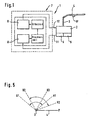
- a windshield wiper device 1 comprises Fig. 1 at least one changeable in its direction of rotation Electric motor 2 and at least one on a motor shaft 3 Articulated wiper arm 4.
- the electric motor can with the help of Pulse width modulation (PMW) changed in speed and thereby, for example, before reaching reversal points be slowed down.
- Sensors are on the electric motor 2 5.6 for tapping the engine speed or for tapping the angle of rotation of the motor shaft 3 is provided.
- Sensor 6 'for querying the shown parking position of the wiper arm 4 may be provided.
- the windshield wiper device 1 further comprises a control unit 7, for example with processors, which cooperates with the sensors 5, 6 8 for detecting the engine speed.
- the control unit (7) allows the electric motor to be closed depending on the load Taxes.
- An arrangement for Direction of rotation control 9 may be provided.
- the direction of rotation control However, 9 is not absolutely necessary, so that too Embodiments without such arrangements are conceivable.
- the The device shown in Fig. 1 is the following, functional Context.
- the electric motor 2 from the control unit 7 switching signals 10, which serve to turn the electric motor 2 on or off or in its Reverse direction of rotation.
- the switching signals 10 are in the Figure shown schematically.
- the electric motor 2 feeds the electric motor 2 assigned sensors 5,6 operational information regarding Speed, speed and angle of rotation Motor shaft 3 as operating signals 11 in the control unit 7 on.
- the device 8 for speed detection determined from the Operating signals 11 permanently the operating speed of the electric motor 2.
- the electric motor switched off to overheat the electric motor prevent.
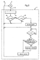
- the electric motor 2 receives from the control unit 7 Switch signal 10 for reversing the direction of rotation or if, for example an arrangement for checking the direction of rotation 9 is provided and this is addressed as described below a switching signal 10, which continues the electric motor 2 unlocked in the same direction of rotation.
- any different operating signals can be used 11 can be fed into the control unit 7 can without leaving the basic idea of the invention. So for example, it can be provided that the sensor 6 ' Parking position of the wiper arm 4 monitored and a corresponding Reports as operating signal 11 to control unit 7, to create additional intervention and control options.
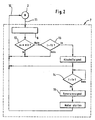
- the function of the device 1 is described below using the Fig. 2 illustrated flow chart explained in more detail.
- Fig. 2 explains in particular those running within the control unit 7 Operations.
- the control unit 7 receives from the electric motor 2, preferably in pulse form, operating signals 11, from which within the device 8 for speed detection the current operating speed is determined or calculated.
- the operating speed is in a downstream comparator 12 compared to a predetermined minimum speed (n min) and decided whether the operating speed is the minimum value falls below. If the operating speed is above or is equal to the minimum speed, there is no change the switching signals 10 for the electric motor 2.
- the control unit 7 sends a switching signal 10 to switch off the electric motor 2.
- subsequent period of time in a second time recording 14 is monitored and referred to as the recovery period te the engine remains switched off. This is from time tracking 14 ensured with the help of a monitoring routine 15.
- the motor cools down within the recovery time, see above that it can be put back into operation safely.
- a switching signal goes from the control unit 7 when the recovery time expires 10 from, with which the electric motor 2 in the reverse direction is put into operation.
- the reversing of the electric motor 2 with the Reversing signal 15 regardless of which direction of rotation Electric motor 2 had before the shutdown process. Because in everyone If the direction of rotation of the electric motor 2 is reversed can be with this procedure on a Direction of rotation control 9 can be dispensed with.
- using a Controller also an operating speed control for adaptation to the target speed.
- the operating signal 11 which corresponds to an operating speed
- a predeterminable Target speed compared and if the Setpoint speed a switching signal 10 for lowering the operating speed submitted.
- the operating speed above the Minimum speed and below the target speed is a Switch signal 10 to increase the speed.
- the Switch control unit 7 off and / or reverse.
- FIG. 4 is part of a flow chart of an embodiment shown, in addition as an incoming operating signal 11 for the control unit 7 vehicle speed signals 15 are provided.
- vehicle speed signals 15 For example, every vehicle speed a certain wiping area size assigned by each an outer and an inner reversing position for the wiper arm 4 is specified.
- a corresponding representation of a Wischfeldes with a parking position P, outer reversing positions U1, U2, U3 and with inner reversing positions V1 and V2 shows Figure 5. It is considered particularly advantageous if the Wiping field size is reduced at higher speeds, to reduce the necessary operating forces for the wiper arm. This is because the wiper arm is smaller Wiping angles the headwind a smaller area of attack offers.
- a wiping angle can be assigned which one covers a smaller area between U1-V1 and U2-V2.
- the vehicle speed using the speed signals 15 to be determined in a computer unit 16.
- a wiping field specification 17 assigned wiping field with the outer and inner reversal positions U and V determined.
- the following steps are now running as follows. With the help of the position detection device 18, which works with operating signals 11 of the sensor 5 permanently monitors whether a reverse position is in close proximity is. If this is not the case, the Switch signals 10 for the electric motor 2.
- the wiping field not only the vehicle speed can be used. It is especially conceivable, the wiping field individually to the respective Adapt driver needs and specifications or to one certain blocking of the wiper arm, so that even with blockages of the wiper arm at least limited wiping operation is made possible. So there are many variations of the Invention conceivable without the basic idea of the invention leave. But all modifications have in common that with you the advantage is connected, the engine speed depends on the load and regulate battery voltage independently. It results in a particularly even wiping process because the Supply voltage does not affect the wiping process due to the speed reduction of the electric motor itself pulls.
Landscapes
- Engineering & Computer Science (AREA)
- Mechanical Engineering (AREA)
- Automation & Control Theory (AREA)
- Control Of Electric Motors In General (AREA)
- Control Of Direct Current Motors (AREA)
- Pharmaceuticals Containing Other Organic And Inorganic Compounds (AREA)
Description
- Fig. 1
- ein schematisches Blockschaltbild der Scheibenwischvorrichtung;
- Fig. 2
- ein Flußdiagramm zur Erläuterung des Signalflusses in der Scheibenwischvorrichtung;
- Fig. 3
- ein Flußdiagramm eines abgewandelten Ausführungsbeispieles mit zusätzlicher Motor-Drehrichtungserkennung;
- Fig. 4
- Flußdiagramm eines Ausführungsbeispieles mit fahrzeuggeschwindigkeitsgekoppelter Wischfeldbeeinflussung;
- Fig. 5
- eine Prinzipskizze zur Wischfeldbeeinflussung gemäß Fig. 4.
Claims (10)
- Scheibenwischvorrichtung mit mindestens einem in seiner Drehrichtung änderbaren Elektromotor (2) und mindestens einem Wischarm (4), wobei eine Steuereinheit (7) zum lastabhängigen Steuern des Elektromotors (2) vorgesehen ist, dadurch gekennzeichnet, daß eine in der Steuereinheit (7) gespeicherte Parkposition des Wischarmes (4) und/oder eine gespeicherte Umkehrposition des Wischarmes (4) an die Fahrzeuggeschwindigkeit angepaßt wird.
- Scheibenwischvorrichtung mit mindestens einem in seiner Drehrichtung änderbaren Elektromotor (2) und mindestens einem Wischarm (4), wobei eine Einrichtung (8) zur Erfassung der Motordrehzahl vorgesehen ist, der Motordrehzahl entsprechende Betriebssignale (11) einer Steuereinheit (7) zugeführt und mit einer Soll-Drehzahl verglichen werden und bei Unterschreiten der Soll-Drehzahl ein Abschalt- und/oder Reversiersignal zur Drehrichtungsumkehr als Schaltsignal (10) dem Elektromotor (2) zugeführt wird, dadurch gekennzeichnet, daß eine in der Steuereinheit (7) gespeicherte Parkposition des Wischarmes (4) und/oder eine gespeicherte Umkehrposition des Wischarmes (4) an die Fahrzeuggeschwindigkeit angepaßt wird.
- Scheibenwischvorrichtung nach Anspruch 1, dadurch gekennzeichnet, daß das Schaltsignal (10) zum reversieren des Elektromotors (2) nach Ablauf einer bestimmten Zeitspanne (tb) erfolgt, in der die Betriebsdrehzahl unter die Minimaldrehzahl sinkt.
- Scheibenwischvorrichtung nach einem oder mehreren der vorhergehenden Ansprüche, dadurch gekennzeichnet, daß die Steuereinheit (7) Blockierpositionen des Wischarmes (4) erfaßt und der Elektromotor (2) vor Erreichen der Blockierpositionen mit Hilfe von Schaltsignalen (10) reversiert wird.
- Scheibenwischvorrichtung nach einem oder mehreren der vorhergehenden Ansprüche, dadurch gekennzeichnet, daß die Steuereinheit (7) Motordrehwinkelsignale als Betriebssignale (11) erfaßt, wobei dem Elektromotor (2) vor Erreichen von Drehwinkeln, welche einer Wischerendlage entsprechen, Drehgeschwindigkeitsänderungssignale als Schaltsignale (10) zugeführt werden und dadurch abbremst.
- Scheibenwischvorrichtung nach einem oder mehreren der vorhergehenden Ansprüche, dadurch gekennzeichnet, daß zur Erfassung der Motordrehzahl und des Motordrehwinkels zumindest ein Sensor (5,6) nach Art eines Hall-Elementes vorgesehen ist.
- Scheibenwischvorrichtung nach einem oder mehreren der vorhergehenden Ansprüche, dadurch gekennzeichnet, daß ein zusätzlicher Sensor (6') zur Überwachung der Parkstellung des Wischarmes (4) vorgesehen ist.
- Scheibenwischvorrichtung nach einem oder mehreren der vorhergehenden Ansprüche, dadurch gekennzeichnet, daß eine Einrichtung (9) zur Motordrehrichtungsüberwachung vorgesehen ist und dem Elektromotor (2) in Abhängigkeit von der Motordrehrichtung ein Reversiersignal als Schaltsignal (10) zugeführt wird.
- Scheibenwischvorrichtung nach einem oder mehreren der vorhergehenden Ansprüche, dadurch gekennzeichnet, daß der Steuereinheit (7) Fahrzeuggeschwindigkeitssignale als Betriebssignale (11) zugeführt werden und in Abhängigkeit von der Fahrzeuggeschwindigkeit unterschiedliche Umkehrpunkte (U, V) für den Wischarm (4) vorgesehen sind und entsprechende Reversiersignale als Schaltsignale (10) zur Drehrichtungsumkehr dem Elektromotor (2) zugeführt werden.
- Scheibenwischvorrichtung nach Anspruch 1, dadurch gekennzeichnet, daß die Steuereinheit (7) mit einem zusätzlichen Regler versehen ist, wobei die Betriebsdrehzahl mit einer Solldrehzahl verglichen wird und bei Abweichungen von der Solldrehzahl ein Schaltsignal (10) zur Anpassung der Betriebsdrehzahl an die Solldrehzahl abgegeben wird.
Applications Claiming Priority (3)
| Application Number | Priority Date | Filing Date | Title |
|---|---|---|---|
| DE19634559A DE19634559A1 (de) | 1996-08-27 | 1996-08-27 | Scheibenwischvorrichtung |
| DE19634559 | 1996-08-27 | ||
| PCT/EP1997/004115 WO1998008717A1 (de) | 1996-08-27 | 1997-07-29 | Scheibenwischvorrichtung |
Publications (2)
| Publication Number | Publication Date |
|---|---|
| EP0921968A1 EP0921968A1 (de) | 1999-06-16 |
| EP0921968B1 true EP0921968B1 (de) | 2001-11-14 |
Family
ID=7803793
Family Applications (1)
| Application Number | Title | Priority Date | Filing Date |
|---|---|---|---|
| EP97934553A Expired - Lifetime EP0921968B1 (de) | 1996-08-27 | 1997-07-29 | Scheibenwischvorrichtung |
Country Status (4)
| Country | Link |
|---|---|
| EP (1) | EP0921968B1 (de) |
| DE (2) | DE19634559A1 (de) |
| ES (1) | ES2163185T3 (de) |
| WO (1) | WO1998008717A1 (de) |
Families Citing this family (12)
| Publication number | Priority date | Publication date | Assignee | Title |
|---|---|---|---|---|
| DE19732520A1 (de) * | 1997-07-29 | 1999-02-04 | Itt Mfg Enterprises Inc | Scheibenwischvorrichtung |
| DE19741630B4 (de) * | 1997-09-20 | 2006-04-27 | Volkswagen Ag | Wischvorrichtung |
| DE19746375A1 (de) | 1997-10-21 | 1999-04-22 | Itt Mfg Enterprises Inc | Schaltungsanordnung zur Geschwindigkeitsreduzierung im Umkehrbereich eines Scheibenwischers mit einem in seiner Pulsweite gesteuerten Motor |
| FR2802876B1 (fr) * | 1999-12-27 | 2002-03-15 | Valeo Systemes Dessuyage | Dispositif d'essuyage et procede d'initialisation automatique du systeme de commande du moteur du dispositif d'essuyage |
| DE10009797B4 (de) * | 2000-03-01 | 2008-05-15 | Valeo Auto-Electric Wischer Und Motoren Gmbh | Scheibenwischervorrichtung zum Wischen von Scheiben |
| DE10024255A1 (de) * | 2000-05-17 | 2001-11-22 | Bosch Gmbh Robert | Scheibenwischervorrichtung, insbesondere für ein Kraftfahrzeug |
| DE10113678A1 (de) * | 2001-03-21 | 2002-10-02 | Bosch Gmbh Robert | Wischeranlage mit zwei Scheibenwischern |
| DE10307959B4 (de) * | 2003-02-24 | 2015-03-12 | Volkswagen Ag | Vorrichtung und Verfahren zum Betreiben eines Scheibenwischers eines Kraftfahrzeugs |
| DE102008000964B4 (de) * | 2008-04-03 | 2019-07-04 | Robert Bosch Gmbh | Scheibenwischer Reversierelektronik mit bi-stabilem Relais |
| FR2947785B1 (fr) * | 2009-07-07 | 2011-11-11 | Eurocopter France | Procede pour nettoyer un pare-brise d'un vehicule, et essuie-glace mettant en oeuvre ledit procede |
| DE102009055169A1 (de) | 2009-12-22 | 2011-06-30 | Robert Bosch GmbH, 70469 | Wischersteuerung |
| DE102021204527A1 (de) * | 2021-05-05 | 2022-11-10 | Robert Bosch Gesellschaft mit beschränkter Haftung | Verfahren zu einem Betrieb einer Wischervorrichtung |
Family Cites Families (9)
| Publication number | Priority date | Publication date | Assignee | Title |
|---|---|---|---|---|
| DE2852676C2 (de) * | 1978-12-06 | 1987-01-29 | SWF Auto-Electric GmbH, 7120 Bietigheim-Bissingen | Schaltanordnung für einen Wischermotor und Wischermotor |
| DE2918658C3 (de) * | 1979-05-09 | 1988-07-07 | SWF Auto-Electric GmbH, 7120 Bietigheim-Bissingen | Wischanlage für Fahrzeuge |
| DE2922160A1 (de) * | 1979-05-31 | 1980-12-04 | Rau Swf Autozubehoer | Wischanlage fuer kraftfahrzeuge |
| FR2541639B1 (fr) * | 1983-02-25 | 1988-06-03 | Marchal Equip Auto | Systeme d'essuie-glace a detecteur de surcharge commandant l'inversion du sens de rotation des balais |
| JPH03239174A (ja) * | 1990-02-16 | 1991-10-24 | Jidosha Denki Kogyo Co Ltd | ワイパ制御装置 |
| DE4018713C2 (de) * | 1990-06-12 | 1999-06-10 | Bosch Gmbh Robert | Scheibenwischvorrichtung |
| DE4130065C2 (de) * | 1991-09-11 | 1993-12-02 | Licentia Gmbh | Elektrischer Scheibenwischerantrieb |
| DE4431699A1 (de) * | 1994-09-06 | 1996-03-07 | Bosch Gmbh Robert | Scheibenwischvorrichtung |
| FR2736023B1 (fr) * | 1995-06-29 | 1997-08-08 | Renault | Dispositif de protection d'un moteur d'essuie-vitres dans un vehicule automobile et son procede de commande |
-
1996
- 1996-08-27 DE DE19634559A patent/DE19634559A1/de not_active Withdrawn
-
1997
- 1997-07-29 ES ES97934553T patent/ES2163185T3/es not_active Expired - Lifetime
- 1997-07-29 DE DE59705404T patent/DE59705404D1/de not_active Expired - Lifetime
- 1997-07-29 WO PCT/EP1997/004115 patent/WO1998008717A1/de not_active Ceased
- 1997-07-29 EP EP97934553A patent/EP0921968B1/de not_active Expired - Lifetime
Also Published As
| Publication number | Publication date |
|---|---|
| EP0921968A1 (de) | 1999-06-16 |
| ES2163185T3 (es) | 2002-01-16 |
| WO1998008717A1 (de) | 1998-03-05 |
| DE19634559A1 (de) | 1998-03-05 |
| DE59705404D1 (de) | 2001-12-20 |
Similar Documents
| Publication | Publication Date | Title |
|---|---|---|
| EP2117888B1 (de) | Vorrichtung und verfahren zur ansteuerung einer antriebseinheit einer wischanlage | |
| WO1999006251A1 (de) | Scheibenwischvorrichtung | |
| DD300360A5 (de) | Hilfskraftlenkung für Kraftfahrzeuge | |
| DE102009047211A1 (de) | Steuervorrichtung und Steuerverfahren für die Antriebseinheit einer Scheibenwischanlage | |
| DE19634559A1 (de) | Scheibenwischvorrichtung | |
| DE102019204913A1 (de) | Verfahren und Vorrichtung zum Betreiben einer Lenkung eines Kraftfahrzeugs sowie Steuergerät und Lenkung | |
| EP2467283B1 (de) | Scheibenwischvorrichtung | |
| DE102014210069A1 (de) | Sensorlose BEMF-Messung für stromgeregelte bürstenlose Motoren | |
| DE19548077A1 (de) | Treibersteuerung f}r einen Servomotor | |
| EP1286870B1 (de) | Scheibenwischvorrichtung, insbesondere für ein kraftfahrzeug | |
| EP0999960A1 (de) | Wischvorrichtung für scheiben von fahrzeugen | |
| EP1134145A2 (de) | Schutzeinrichtung für eine elektrische Lenkung | |
| DE102005051257A1 (de) | Motorsteuerung | |
| DE10145103B4 (de) | Wischanlage für Fahrzeuge, insbesondere für Automobil-Windschutzscheiben | |
| DE3347546C2 (de) | Scheibenwischvorrichtung für Kraftfahrzeuge | |
| DE4032922C3 (de) | Verfahren zum Wischen einer Scheibe | |
| DE102005045921B4 (de) | Verfahren zum Wischen einer Scheibe sowie Scheibenwischvorrichtung, insbesondere für ein Kraftfahrzeug | |
| EP1672777B1 (de) | Betätigungsvorrichtung für Kraftfahrzeugkomponenten | |
| EP1146405B1 (de) | Regelverfahren | |
| DE19741629B4 (de) | Wischvorrichtung | |
| DE10259732A1 (de) | Scheibenwischersteuerung | |
| EP2170655B1 (de) | Ansteuerverfahren und ansteuerschaltung für einen motorantrieb einer elektronischen lenkungsverriegelung | |
| DE4213980A1 (de) | Hydraulische servolenkung mit geschwindigkeitsabhaengiger ventilkennlinie | |
| DE102005006669B4 (de) | Verfahren zum Betreiben eines Antriebes für eine Scheibenwischvorrichtung und entsprechender Antrieb | |
| EP1407536B1 (de) | Verfahren zur gleichmässigen laufsteuerung eines reluktanzmotors und einrichtung zur einschaltstrom begrenzung |
Legal Events
| Date | Code | Title | Description |
|---|---|---|---|
| PUAI | Public reference made under article 153(3) epc to a published international application that has entered the european phase |
Free format text: ORIGINAL CODE: 0009012 |
|
| 17P | Request for examination filed |
Effective date: 19990315 |
|
| AK | Designated contracting states |
Kind code of ref document: A1 Designated state(s): DE ES FR GB IT |
|
| 17Q | First examination report despatched |
Effective date: 20000811 |
|
| GRAG | Despatch of communication of intention to grant |
Free format text: ORIGINAL CODE: EPIDOS AGRA |
|
| RAP1 | Party data changed (applicant data changed or rights of an application transferred) |
Owner name: VALEO AUTO-ELECTRIC WISCHER UND MOTOREN GMBH |
|
| GRAG | Despatch of communication of intention to grant |
Free format text: ORIGINAL CODE: EPIDOS AGRA |
|
| GRAH | Despatch of communication of intention to grant a patent |
Free format text: ORIGINAL CODE: EPIDOS IGRA |
|
| GRAH | Despatch of communication of intention to grant a patent |
Free format text: ORIGINAL CODE: EPIDOS IGRA |
|
| ITF | It: translation for a ep patent filed | ||
| GRAA | (expected) grant |
Free format text: ORIGINAL CODE: 0009210 |
|
| AK | Designated contracting states |
Kind code of ref document: B1 Designated state(s): DE ES FR GB IT |
|
| REF | Corresponds to: |
Ref document number: 59705404 Country of ref document: DE Date of ref document: 20011220 |
|
| REG | Reference to a national code |
Ref country code: GB Ref legal event code: IF02 |
|
| REG | Reference to a national code |
Ref country code: ES Ref legal event code: FG2A Ref document number: 2163185 Country of ref document: ES Kind code of ref document: T3 |
|
| GBT | Gb: translation of ep patent filed (gb section 77(6)(a)/1977) |
Effective date: 20020122 |
|
| ET | Fr: translation filed | ||
| PLBE | No opposition filed within time limit |
Free format text: ORIGINAL CODE: 0009261 |
|
| STAA | Information on the status of an ep patent application or granted ep patent |
Free format text: STATUS: NO OPPOSITION FILED WITHIN TIME LIMIT |
|
| 26N | No opposition filed | ||
| REG | Reference to a national code |
Ref country code: FR Ref legal event code: PLFP Year of fee payment: 20 |
|
| PGFP | Annual fee paid to national office [announced via postgrant information from national office to epo] |
Ref country code: DE Payment date: 20160719 Year of fee payment: 20 Ref country code: GB Payment date: 20160719 Year of fee payment: 20 Ref country code: IT Payment date: 20160725 Year of fee payment: 20 |
|
| PGFP | Annual fee paid to national office [announced via postgrant information from national office to epo] |
Ref country code: FR Payment date: 20160729 Year of fee payment: 20 |
|
| PGFP | Annual fee paid to national office [announced via postgrant information from national office to epo] |
Ref country code: ES Payment date: 20160729 Year of fee payment: 20 |
|
| REG | Reference to a national code |
Ref country code: DE Ref legal event code: R071 Ref document number: 59705404 Country of ref document: DE |
|
| REG | Reference to a national code |
Ref country code: GB Ref legal event code: PE20 Expiry date: 20170728 |
|
| PG25 | Lapsed in a contracting state [announced via postgrant information from national office to epo] |
Ref country code: GB Free format text: LAPSE BECAUSE OF EXPIRATION OF PROTECTION Effective date: 20170728 |
|
| REG | Reference to a national code |
Ref country code: ES Ref legal event code: FD2A Effective date: 20180508 |
|
| PG25 | Lapsed in a contracting state [announced via postgrant information from national office to epo] |
Ref country code: ES Free format text: LAPSE BECAUSE OF EXPIRATION OF PROTECTION Effective date: 20170730 |