EP0921300A2 - Spritzverstelleinrichtung für Kraftstoffpumpe - Google Patents
Spritzverstelleinrichtung für Kraftstoffpumpe Download PDFInfo
- Publication number
- EP0921300A2 EP0921300A2 EP98309187A EP98309187A EP0921300A2 EP 0921300 A2 EP0921300 A2 EP 0921300A2 EP 98309187 A EP98309187 A EP 98309187A EP 98309187 A EP98309187 A EP 98309187A EP 0921300 A2 EP0921300 A2 EP 0921300A2
- Authority
- EP
- European Patent Office
- Prior art keywords
- piston
- advance
- light load
- fuel
- servo
- Prior art date
- Legal status (The legal status is an assumption and is not a legal conclusion. Google has not performed a legal analysis and makes no representation as to the accuracy of the status listed.)
- Granted
Links
Images
Classifications
-
- F—MECHANICAL ENGINEERING; LIGHTING; HEATING; WEAPONS; BLASTING
- F02—COMBUSTION ENGINES; HOT-GAS OR COMBUSTION-PRODUCT ENGINE PLANTS
- F02M—SUPPLYING COMBUSTION ENGINES IN GENERAL WITH COMBUSTIBLE MIXTURES OR CONSTITUENTS THEREOF
- F02M41/00—Fuel-injection apparatus with two or more injectors fed from a common pressure-source sequentially by means of a distributor
- F02M41/08—Fuel-injection apparatus with two or more injectors fed from a common pressure-source sequentially by means of a distributor the distributor and pumping elements being combined
- F02M41/14—Fuel-injection apparatus with two or more injectors fed from a common pressure-source sequentially by means of a distributor the distributor and pumping elements being combined rotary distributor supporting pump pistons
- F02M41/1405—Fuel-injection apparatus with two or more injectors fed from a common pressure-source sequentially by means of a distributor the distributor and pumping elements being combined rotary distributor supporting pump pistons pistons being disposed radially with respect to rotation axis
- F02M41/1411—Fuel-injection apparatus with two or more injectors fed from a common pressure-source sequentially by means of a distributor the distributor and pumping elements being combined rotary distributor supporting pump pistons pistons being disposed radially with respect to rotation axis characterised by means for varying fuel delivery or injection timing
- F02M41/1416—Devices specially adapted for angular adjustment of annular cam
-
- F—MECHANICAL ENGINEERING; LIGHTING; HEATING; WEAPONS; BLASTING
- F02—COMBUSTION ENGINES; HOT-GAS OR COMBUSTION-PRODUCT ENGINE PLANTS
- F02D—CONTROLLING COMBUSTION ENGINES
- F02D1/00—Controlling fuel-injection pumps, e.g. of high pressure injection type
- F02D1/16—Adjustment of injection timing
- F02D1/18—Adjustment of injection timing with non-mechanical means for transmitting control impulse; with amplification of control impulse
- F02D1/183—Adjustment of injection timing with non-mechanical means for transmitting control impulse; with amplification of control impulse hydraulic
Definitions
- This invention relates to an advance arrangement for use in controlling the timing of fuel delivery by a high pressure fuel pump intended for use in a compression ignition internal combustion engine.
- the invention relates to a servo-type advance arrangement including light load and cold advance features.
- the advance arrangement is configured so that, beyond a predetermined position of the advance piston, fuel from the temperature control valve is no longer applied to the light load piston.
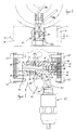
- Figures 1 and 2 illustrate part of a rotary fuel pump which includes a cam ring which is angularly adjustable with respect to a pump housing, the cam ring including a plurality of cam lobes.
- the cam ring encircles part of a distributor member which includes pumping plungers reciprocable within respective bores of the distributor member, the plungers having associated therewith respective shoe and roller arrangements the rollers of which are engageable with the cam surface of the cam ring.
- fuel is supplied to the bores of the distributor member by a transfer pump, pushing the plungers thereof radially outwards.
- the output pressure of the transfer pump is controlled so as to be related to the speed of operation of the engine with which the pump is being used.
- Rotation of the distributor member relative to the cam ring causes the rollers to move relative to the cam ring, engagement of the rollers with the cam lobes causing the plungers to be forced inwards, pressurizing the fuel within the bores, and causing fuel to be delivered by the fuel pump at high pressure.
- the timing at which fuel is delivered by the pump can be adjusted.
- the advance piston 12 includes an axially extending bore 22 within which a servo-piston member 24 is slidable.
- a light load piston 26 is also received within the bore 14, the light load piston 26 including a central opening through which the servo-piston 24 extends, the servo-piston 24 acting to guide movement of the light load piston 26, the servo-piston 24 being a substantially fluid tight, sliding fit within the opening of the light load piston 26 and within the bore 22 of the advance piston 12.
- a light load control spring 28 is engaged between the light load piston 26 and one of the plates 18 to bias the light load piston 26 into engagement with a step defined by part of the bore 14.
- the end of the bore 22 remote from the light load piston 26 is closed by means of a disk-shaped member 36 which is located within an annular groove formed in the advance piston 12, the location of the member 36 being achieved, for example, using an appropriate thermal expansion technique.
- the bore may be closed by means of a core plug, bolt or the like.
- a first control chamber 38 is defined by an end face of the advance piston 12 remote from the light load piston 26, the associated part of the bore 14, and the associated end plate 18.
- the first control chamber 38 communicates via a channel 40 formed in the outer periphery of the advance piston 12 with a radially extending passage 42 within which a non-return valve 46 is located.
- the radially extending passage 42 communicates with the bore 22, and depending upon the position of the servo-piston 24, the radially extending passage 42 may communicate with a second radially extending passage 44 which opens into a recess 48 provided in the outer surface of the advance piston 12.
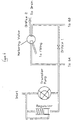
- the recess 48 is located so that for all permitted positions of the advance piston 12 relative to the housing 16, the recess 48 communicates with a passage 50 which communicates with a chamber defined between the housing 16 and an electromagnetically operated temperature control valve 52 mounted upon the housing 16, the chamber communicating constantly with a bore 64 which communicates with a bore 62.
- the bore 62 contains a passage defining member 62a which ensures that the bore 64 communicates, constantly, with a passage 64a containing fuel at transfer pressure, and the passage communicates with a drilling 60a which communicates with a metering valve.
- the outer surface of the advance piston 12 is provided with a short flat 66 which, depending upon the axial position of the advance piston 12, is arranged to communicate with a passage 68 which communicates with the temperature control valve 52.
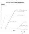
- Figure 3 illustrates the load and speed advance characteristics for the fuel pump under full load advance conditions where the engine is hot, and as illustrated in Figure 3, the maximum permitted advance is relatively low. In practice, the maximum advance is limited by the engagement of the end of the advance piston 12 remote from the control chamber 38 with the light load piston 26.
- the metering valve allows the pressure applied to the passage 60 to rise.
- the fuel pressure applied to the second control chamber 54 hence rises.
- the application of fuel at increased pressure to this chamber results in movement of the light load piston 26 against the action of the spring 28.
- the movement of the light load piston 26 reduces the compression of the spring 30, and the application of fuel to the chamber 70 as described hereinbefore causes movement of the servo-piston 24 to the left in the orientation illustrated.
- the movement of the servo-piston 24 permits fuel to flow to the first control chamber 38 resulting in movement of the advance piston 12 to the left, advancing the timing of fuel delivery by the pump.
- the temperature control valve 52 may be switched in order to adjust timing to compensate for the engine being cold.
- the effect of switching the temperature control valve 52 is that fuel at transfer pressure is supplied to the passage 68.
- fuel from the passage 68 flows through the flat 66 to the recess 58 and from there to the second control chamber 54.
- the application of fuel to the second control chamber 54 results in movement of the light load piston 26, and described hereinbefore, this results in adjustment of the position of the advance piston 12.
- the provision of such an advance arrangement has the advantage that the high load conditions can operate over an increased pressure range, thus permitting an increase in the stiffness of the spring 30 resulting in greater stability and more consistent operation.
- the light load advance condition can also operate over a larger pressure range without interfering with the operation of the advance arrangement under full load conditions.
- the characteristics of these springs can be optimised for the pump with which the advance arrangement is to be used. Also, as, at full load, movement of the servo-piston 24 is limited by engagement with the light load piston 26, the maximum advance position of the advance piston 12 is well defined, and operation of the engine under these conditions is more stable.
- the length of the flat 66 is of less importance as the position of the low load piston 26 is determined by the pressure of fuel supplied through the passage 60 to the second control chamber 54 under these conditions.
Applications Claiming Priority (2)
| Application Number | Priority Date | Filing Date | Title |
|---|---|---|---|
| GB9725415 | 1997-12-02 | ||
| GBGB9725415.5A GB9725415D0 (en) | 1997-12-02 | 1997-12-02 | Advance arrangement |
Publications (3)
| Publication Number | Publication Date |
|---|---|
| EP0921300A2 true EP0921300A2 (de) | 1999-06-09 |
| EP0921300A3 EP0921300A3 (de) | 2000-08-23 |
| EP0921300B1 EP0921300B1 (de) | 2003-06-11 |
Family
ID=10822944
Family Applications (1)
| Application Number | Title | Priority Date | Filing Date |
|---|---|---|---|
| EP98309187A Expired - Lifetime EP0921300B1 (de) | 1997-12-02 | 1998-11-10 | Spritzverstelleinrichtung für Kraftstoffpumpe |
Country Status (5)
| Country | Link |
|---|---|
| US (1) | US6041759A (de) |
| EP (1) | EP0921300B1 (de) |
| JP (1) | JPH11229992A (de) |
| DE (1) | DE69815477T2 (de) |
| GB (1) | GB9725415D0 (de) |
Cited By (7)
| Publication number | Priority date | Publication date | Assignee | Title |
|---|---|---|---|---|
| EP1035311A2 (de) | 1999-03-10 | 2000-09-13 | Delphi Technologies, Inc. | Spritzverstelleinrichtung für Kraftstoffeinspritzpumpe |
| EP1167723A2 (de) | 2000-06-22 | 2002-01-02 | Delphi Technologies, Inc. | Einspritzzeitpunktversteller |
| GB2370885A (en) * | 2000-11-09 | 2002-07-10 | Stanadyne Corp | Servo controlled timing advance for unit pump or unit injector |
| WO2002061250A1 (en) * | 2001-02-01 | 2002-08-08 | Delphi Technologies, Inc. | Advance arrangement |
| EP1296041A2 (de) | 2001-09-24 | 2003-03-26 | Delphi Technologies, Inc. | Spritzverstelleinrichtung |
| EP1296052A2 (de) | 2001-09-24 | 2003-03-26 | Delphi Technologies, Inc. | Einrichtung zum Verstellen des Einspritzzeitpunktes |
| EP1300568A2 (de) * | 2001-10-03 | 2003-04-09 | Delphi Technologies, Inc. | Dosierventilanordnung |
Families Citing this family (5)
| Publication number | Priority date | Publication date | Assignee | Title |
|---|---|---|---|---|
| US6546916B2 (en) * | 1999-03-10 | 2003-04-15 | Delphi Technologies, Inc. | Fuel injection pump timing mechanism |
| JP4315356B2 (ja) * | 1999-08-24 | 2009-08-19 | ヤマハ発動機株式会社 | 筒内燃料噴射式エンジンの制御装置 |
| EP1749996B1 (de) * | 2005-08-01 | 2008-07-23 | Delphi Technologies, Inc. | Einspritzverstelleinrichtung |
| US7350508B1 (en) * | 2006-10-12 | 2008-04-01 | Delphi Technologies, Inc. | Advance arrangements |
| GB2468872B (en) * | 2009-03-25 | 2013-07-17 | Bamford Excavators Ltd | A method of operating a compression ignition engine by altering the fuel injection timing based on sensed engine parameters |
Citations (2)
| Publication number | Priority date | Publication date | Assignee | Title |
|---|---|---|---|---|
| US4037574A (en) | 1976-05-21 | 1977-07-26 | Stanadyne, Inc. | Timing control for fuel injection pump |
| US4037573A (en) | 1976-05-21 | 1977-07-26 | Stanadyne, Inc. | Timing control for fuel injection pump |
Family Cites Families (5)
| Publication number | Priority date | Publication date | Assignee | Title |
|---|---|---|---|---|
| DE3611044A1 (de) * | 1986-04-02 | 1987-10-08 | Bosch Gmbh Robert | Verstelleinrichtung fuer den spritzbeginn bei einer kraftstoffeinspritzpumpe |
| US5263457A (en) * | 1989-12-06 | 1993-11-23 | Robert Bosch Gmbh | Fuel injection pump for internal combustion engines |
| DE4117813A1 (de) * | 1991-05-31 | 1992-12-03 | Bosch Gmbh Robert | Kraftstoffeinspritzpumpe fuer brennkraftmaschinen |
| GB9226669D0 (en) * | 1992-12-22 | 1993-02-17 | Lucas Ind Plc | Fuel pump |
| DE19549046A1 (de) * | 1995-12-28 | 1997-07-03 | Bosch Gmbh Robert | Kraftstoffeinspritzpumpe für Brennkraftmaschinen |
-
1997
- 1997-12-02 GB GBGB9725415.5A patent/GB9725415D0/en not_active Ceased
-
1998
- 1998-11-10 EP EP98309187A patent/EP0921300B1/de not_active Expired - Lifetime
- 1998-11-10 DE DE69815477T patent/DE69815477T2/de not_active Expired - Lifetime
- 1998-11-19 US US09/196,082 patent/US6041759A/en not_active Expired - Lifetime
- 1998-12-02 JP JP10343168A patent/JPH11229992A/ja not_active Withdrawn
Patent Citations (2)
| Publication number | Priority date | Publication date | Assignee | Title |
|---|---|---|---|---|
| US4037574A (en) | 1976-05-21 | 1977-07-26 | Stanadyne, Inc. | Timing control for fuel injection pump |
| US4037573A (en) | 1976-05-21 | 1977-07-26 | Stanadyne, Inc. | Timing control for fuel injection pump |
Cited By (16)
| Publication number | Priority date | Publication date | Assignee | Title |
|---|---|---|---|---|
| EP1035311A3 (de) * | 1999-03-10 | 2001-09-19 | Delphi Technologies, Inc. | Spritzverstelleinrichtung für Kraftstoffeinspritzpumpe |
| EP1035311A2 (de) | 1999-03-10 | 2000-09-13 | Delphi Technologies, Inc. | Spritzverstelleinrichtung für Kraftstoffeinspritzpumpe |
| EP1167723A2 (de) | 2000-06-22 | 2002-01-02 | Delphi Technologies, Inc. | Einspritzzeitpunktversteller |
| EP1167723A3 (de) * | 2000-06-22 | 2002-06-19 | Delphi Technologies, Inc. | Einspritzzeitpunktversteller |
| GB2370885B (en) * | 2000-11-09 | 2004-08-11 | Stanadyne Corp | Servo controlled timing advance for unit pump or unit injector |
| GB2370885A (en) * | 2000-11-09 | 2002-07-10 | Stanadyne Corp | Servo controlled timing advance for unit pump or unit injector |
| WO2002061250A1 (en) * | 2001-02-01 | 2002-08-08 | Delphi Technologies, Inc. | Advance arrangement |
| EP1526264A1 (de) * | 2001-02-01 | 2005-04-27 | Delphi Technologies, Inc. | Einspritzverstelleinrichtung |
| US6941932B2 (en) | 2001-02-01 | 2005-09-13 | Delphi Technologies, Inc. | Advance arrangement |
| EP1296041A2 (de) | 2001-09-24 | 2003-03-26 | Delphi Technologies, Inc. | Spritzverstelleinrichtung |
| EP1296041A3 (de) * | 2001-09-24 | 2004-07-07 | Delphi Technologies, Inc. | Spritzverstelleinrichtung |
| EP1296052A3 (de) * | 2001-09-24 | 2004-06-16 | Delphi Technologies, Inc. | Einrichtung zum Verstellen des Einspritzzeitpunktes |
| EP1296052A2 (de) | 2001-09-24 | 2003-03-26 | Delphi Technologies, Inc. | Einrichtung zum Verstellen des Einspritzzeitpunktes |
| US6883499B2 (en) | 2001-09-24 | 2005-04-26 | Delphi Technologies, Inc. | Advance arrangement |
| EP1300568A2 (de) * | 2001-10-03 | 2003-04-09 | Delphi Technologies, Inc. | Dosierventilanordnung |
| EP1300568A3 (de) * | 2001-10-03 | 2004-09-22 | Delphi Technologies, Inc. | Dosierventilanordnung |
Also Published As
| Publication number | Publication date |
|---|---|
| EP0921300A3 (de) | 2000-08-23 |
| EP0921300B1 (de) | 2003-06-11 |
| JPH11229992A (ja) | 1999-08-24 |
| DE69815477D1 (de) | 2003-07-17 |
| GB9725415D0 (en) | 1998-01-28 |
| US6041759A (en) | 2000-03-28 |
| DE69815477T2 (de) | 2004-04-29 |
Similar Documents
| Publication | Publication Date | Title |
|---|---|---|
| US4453522A (en) | Apparatus for adjusting the timing of a fuel injection pump | |
| US4586480A (en) | Electronically controlled distributor type fuel injection pump | |
| EP0921300B1 (de) | Spritzverstelleinrichtung für Kraftstoffpumpe | |
| US6363917B1 (en) | Fuel injector pump advance arrangement | |
| US4079719A (en) | Timing control for fuel pump | |
| EP0524132B1 (de) | Brennstoffsystem für eine Rotationsverteilerbrennstoffeinspritzpumpe | |
| EP1749996A1 (de) | Einspritzverstelleinrichtung | |
| JPH0146695B2 (de) | ||
| US4610234A (en) | Injection timing control device for distributor-type fuel injection pumps | |
| US4379442A (en) | Electromagnetically controlled fuel injection pump | |
| EP0715071B1 (de) | Kraftstoffpumpenvorrichtung | |
| US4403582A (en) | Fuel injection control system | |
| EP0684379B1 (de) | Verteiler-Kraftstoffeinspritzpumpe | |
| US6546916B2 (en) | Fuel injection pump timing mechanism | |
| US4598683A (en) | Fuel injection pump of the distribution type | |
| US6413054B1 (en) | Fuel injection pump | |
| US4589394A (en) | Injection timing control device in a distributor-type fuel injection pump | |
| EP1167723B1 (de) | Einspritzzeitpunktversteller | |
| US4793311A (en) | Fuel injection pump with multi-state load/speed control system | |
| US6718951B2 (en) | Advance arrangement | |
| EP1296052B1 (de) | Einrichtung zum Verstellen des Einspritzzeitpunktes | |
| JPH0842362A (ja) | 進角タイミングピストン用マウント | |
| GB2327716A (en) | A control trigger valve for a fuel pump | |
| JPH0115699B2 (de) | ||
| JPH04276173A (ja) | 分配型燃料噴射ポンプの噴射時期調節装置 |
Legal Events
| Date | Code | Title | Description |
|---|---|---|---|
| PUAI | Public reference made under article 153(3) epc to a published international application that has entered the european phase |
Free format text: ORIGINAL CODE: 0009012 |
|
| AK | Designated contracting states |
Kind code of ref document: A2 Designated state(s): DE ES FR GB IT |
|
| AX | Request for extension of the european patent |
Free format text: AL;LT;LV;MK;RO;SI |
|
| RAP1 | Party data changed (applicant data changed or rights of an application transferred) |
Owner name: LUCAS INDUSTRIES LIMITED |
|
| PUAL | Search report despatched |
Free format text: ORIGINAL CODE: 0009013 |
|
| AK | Designated contracting states |
Kind code of ref document: A3 Designated state(s): AT BE CH CY DE DK ES FI FR GB GR IE IT LI LU MC NL PT SE |
|
| AX | Request for extension of the european patent |
Free format text: AL;LT;LV;MK;RO;SI |
|
| 17P | Request for examination filed |
Effective date: 20010119 |
|
| RAP1 | Party data changed (applicant data changed or rights of an application transferred) |
Owner name: DELPHI TECHNOLOGIES, INC. |
|
| AKX | Designation fees paid |
Free format text: DE ES FR GB IT |
|
| GRAH | Despatch of communication of intention to grant a patent |
Free format text: ORIGINAL CODE: EPIDOS IGRA |
|
| GRAH | Despatch of communication of intention to grant a patent |
Free format text: ORIGINAL CODE: EPIDOS IGRA |
|
| GRAA | (expected) grant |
Free format text: ORIGINAL CODE: 0009210 |
|
| AK | Designated contracting states |
Designated state(s): DE ES FR GB IT |
|
| PG25 | Lapsed in a contracting state [announced via postgrant information from national office to epo] |
Ref country code: FR Free format text: LAPSE BECAUSE OF FAILURE TO SUBMIT A TRANSLATION OF THE DESCRIPTION OR TO PAY THE FEE WITHIN THE PRESCRIBED TIME-LIMIT Effective date: 20030611 |
|
| REG | Reference to a national code |
Ref country code: GB Ref legal event code: FG4D |
|
| REF | Corresponds to: |
Ref document number: 69815477 Country of ref document: DE Date of ref document: 20030717 Kind code of ref document: P |
|
| PG25 | Lapsed in a contracting state [announced via postgrant information from national office to epo] |
Ref country code: ES Free format text: LAPSE BECAUSE OF FAILURE TO SUBMIT A TRANSLATION OF THE DESCRIPTION OR TO PAY THE FEE WITHIN THE PRESCRIBED TIME-LIMIT Effective date: 20030922 |
|
| PGFP | Annual fee paid to national office [announced via postgrant information from national office to epo] |
Ref country code: FR Payment date: 20030923 Year of fee payment: 6 |
|
| PG25 | Lapsed in a contracting state [announced via postgrant information from national office to epo] |
Ref country code: GB Free format text: LAPSE BECAUSE OF NON-PAYMENT OF DUE FEES Effective date: 20031110 |
|
| PLBE | No opposition filed within time limit |
Free format text: ORIGINAL CODE: 0009261 |
|
| STAA | Information on the status of an ep patent application or granted ep patent |
Free format text: STATUS: NO OPPOSITION FILED WITHIN TIME LIMIT |
|
| 26N | No opposition filed |
Effective date: 20040312 |
|
| EN | Fr: translation not filed | ||
| GBPC | Gb: european patent ceased through non-payment of renewal fee |
Effective date: 20031110 |
|
| PG25 | Lapsed in a contracting state [announced via postgrant information from national office to epo] |
Ref country code: IT Free format text: LAPSE BECAUSE OF NON-PAYMENT OF DUE FEES Effective date: 20051110 |
|
| REG | Reference to a national code |
Ref country code: FR Ref legal event code: TP |
|
| PGFP | Annual fee paid to national office [announced via postgrant information from national office to epo] |
Ref country code: DE Payment date: 20121128 Year of fee payment: 15 |
|
| REG | Reference to a national code |
Ref country code: FR Ref legal event code: TP Owner name: DELPHI INTERNATIONAL OPERATIONS LUXEMBOURG S.A, LU Effective date: 20140516 |
|
| REG | Reference to a national code |
Ref country code: DE Ref legal event code: R082 Ref document number: 69815477 Country of ref document: DE Representative=s name: MANITZ, FINSTERWALD & PARTNER GBR, DE |
|
| REG | Reference to a national code |
Ref country code: DE Ref legal event code: R082 Ref document number: 69815477 Country of ref document: DE Representative=s name: MANITZ, FINSTERWALD & PARTNER GBR, DE Effective date: 20140702 Ref country code: DE Ref legal event code: R081 Ref document number: 69815477 Country of ref document: DE Owner name: DELPHI INTERNATIONAL OPERATIONS LUXEMBOURG S.A, LU Free format text: FORMER OWNER: DELPHI TECHNOLOGIES HOLDING S.A.R.L., BASCHARAGE, LU Effective date: 20140702 |
|
| REG | Reference to a national code |
Ref country code: DE Ref legal event code: R119 Ref document number: 69815477 Country of ref document: DE Effective date: 20140603 |
|
| PG25 | Lapsed in a contracting state [announced via postgrant information from national office to epo] |
Ref country code: DE Free format text: LAPSE BECAUSE OF NON-PAYMENT OF DUE FEES Effective date: 20140603 |