EP0921022A2 - Trocknerpatrone für Fahrzeugklimaanlage - Google Patents
Trocknerpatrone für Fahrzeugklimaanlage Download PDFInfo
- Publication number
- EP0921022A2 EP0921022A2 EP98120327A EP98120327A EP0921022A2 EP 0921022 A2 EP0921022 A2 EP 0921022A2 EP 98120327 A EP98120327 A EP 98120327A EP 98120327 A EP98120327 A EP 98120327A EP 0921022 A2 EP0921022 A2 EP 0921022A2
- Authority
- EP
- European Patent Office
- Prior art keywords
- dryer cartridge
- cartridge according
- sealing
- sealing ring
- base body
- Prior art date
- Legal status (The legal status is an assumption and is not a legal conclusion. Google has not performed a legal analysis and makes no representation as to the accuracy of the status listed.)
- Granted
Links
Images

Classifications
-
- B—PERFORMING OPERATIONS; TRANSPORTING
- B60—VEHICLES IN GENERAL
- B60H—ARRANGEMENTS OF HEATING, COOLING, VENTILATING OR OTHER AIR-TREATING DEVICES SPECIALLY ADAPTED FOR PASSENGER OR GOODS SPACES OF VEHICLES
- B60H1/00—Heating, cooling or ventilating [HVAC] devices
- B60H1/32—Cooling devices
- B60H1/3204—Cooling devices using compression
- B60H1/3229—Cooling devices using compression characterised by constructional features, e.g. housings, mountings, conversion systems
-
- F—MECHANICAL ENGINEERING; LIGHTING; HEATING; WEAPONS; BLASTING
- F25—REFRIGERATION OR COOLING; COMBINED HEATING AND REFRIGERATION SYSTEMS; HEAT PUMP SYSTEMS; MANUFACTURE OR STORAGE OF ICE; LIQUEFACTION SOLIDIFICATION OF GASES
- F25B—REFRIGERATION MACHINES, PLANTS OR SYSTEMS; COMBINED HEATING AND REFRIGERATION SYSTEMS; HEAT PUMP SYSTEMS
- F25B43/00—Arrangements for separating or purifying gases or liquids; Arrangements for vaporising the residuum of liquid refrigerant, e.g. by heat
- F25B43/003—Filters
-
- F—MECHANICAL ENGINEERING; LIGHTING; HEATING; WEAPONS; BLASTING
- F25—REFRIGERATION OR COOLING; COMBINED HEATING AND REFRIGERATION SYSTEMS; HEAT PUMP SYSTEMS; MANUFACTURE OR STORAGE OF ICE; LIQUEFACTION SOLIDIFICATION OF GASES
- F25B—REFRIGERATION MACHINES, PLANTS OR SYSTEMS; COMBINED HEATING AND REFRIGERATION SYSTEMS; HEAT PUMP SYSTEMS
- F25B2339/00—Details of evaporators; Details of condensers
- F25B2339/04—Details of condensers
- F25B2339/044—Condensers with an integrated receiver
- F25B2339/0441—Condensers with an integrated receiver containing a drier or a filter
Definitions
- the invention relates to a dryer cartridge according to the preamble of claim 1.
- a dryer cartridge known from DE-A-44 02 927 consists of an upper part and a latched lower part.
- an annular groove is formed on the outside Sealing ring with an approximately rectangular cross section holds axially against a seat pressed in the condenser collecting tube and held thereon with axial preload becomes.
- the sealing effect of the sealing ring can subside so that contamination in the refrigerant circuit is unimpeded be transported.
- a sealing ring with a rectangular one Cross section and axial contact to provide a sealing ring with a lip, which should put on the inner wall of the manifold, so that on an annular seat with an axial sealing surface for the sealing ring can be dispensed with.
- the correct collaboration between a sealing lip and the inner wall of the manifold considerable manufacturing and processing effort, careful assembly, and is unable to reliably compensate for manufacturing tolerances.
- the invention has for its object a dryer cartridge for a vehicle air conditioning system to create, despite the reduced manufacturing costs and simplified Installation provides a reliable seal in all operating conditions is that not only manufacturing tolerances but also operational influences can compensate.
- the sealing ring arranged on the dryer cartridge encloses the seat like a cuff, so that there is no leakage through the seat.
- the at least two elastic Sealing lips support each other to create a perfect seal, even if manufacturing tolerances and / or operational influences are compensating.
- Each sealing lip can already provide a perfect seal generate and adapt to the local conditions by deforming. If one sealing lip alone is not enough, another comes to the rescue, also because because the sealing ring works in an axially relatively extensive sealing area.
- the sealing ring can be manufactured inexpensively and is easy to attach.
- the sealing ring takes up little installation space, the sealing lips have a lot of room for deformation in the radial and axial directions automatically bring them into optimal sealing positions.
- the sealing lips are mutually the same height, expediently higher than the radial thickness of the base body. But it is also conceivable that Design sealing lips of different heights, i.e. the front one in the direction of insertion Sealing lip e.g. to be lower than the rearmost sealing lip in the direction of insertion.
- the sealing lips are spaced approximately the same distance apart. They allow each other a relatively large deformation space.
- the sealing lips are radially and axially relatively easily deformable and thereby able to adapt itself to the given installation conditions adapt.
- the ridges of the sealing lips should be rounded to be unique To achieve investment conditions for effective sealing. But it would be it is also conceivable to let the sealing lips run out like a knife, because then they if necessary, better adapt to the installation conditions.
- HNBR with a Shore hardness of around 70 is particularly useful Material for the one-piece production of the sealing ring because of this material relatively insensitive to temperature and pressure and immune to that in vehicle air conditioning systems refrigerant used.
- a pot-like end part is particularly expedient, according to claim 9 creates the possibility to offer a large cross-section on the downstream side, so that Filter material (pore size 10 to 200 ⁇ m) while retaining even the finest particles, which cannot avoid the sealing ring, the flow resistance at maximum Delivery rate does not increase inappropriately.
- the end part is expediently a separate one, so to speak Molding and subsequently set on the base of the cartridge.
- This has important ones Manufacturing advantages and simplifies the assembly of the sealing ring because it is already can be attached to this or to the base body before the end part is attached. It differently dimensioned base bodies and molded parts can be built like a modular system combine that only have to fit together in the connection area.
- separated particles are collected in the collar, so that they are simply disposed of when the dryer cartridge is removed.
- the safety filter ensures a break in the fine-pored Filter material that no parts of the batch are rinsed out. Besides, can the safety filter supports the weaker filter material in the event of deformation, so that there is no breakage of the fine-pored filter material.
- a dryer cartridge P used for receiving and positioning a desiccator batch through which the refrigerant flows D is designed to be able to extract water from the refrigerant.
- the Dryer cartridge P is interchangeable and may be in its operating position set by holding elements, not shown.
- the dryer cartridge P in a seat of a dryer container or accumulator, both not shown, a vehicle air conditioning system can be used interchangeably.
- an inverted hat-shaped insert V for example made of metal, used, which serves to position the dryer cartridge P and at the same time Separation between the inflow and the outflow side creates the whole Forcing refrigerant to flow through the dryer cartridge P.
- the insert V is fastened with its hat brim 3 to an inner wall 1 and lies with a bottom 5 a hat cup 2 adjacent to a bottom wall 6.
- the hat bowl tapers in the direction of insertion the dryer cartridge P (from top to bottom in Fig. 1).
- In the hat bowl 2 through openings 8 are provided adjacent to the actual seating area.
- the insert V forms a seat.
- the dryer cartridge P is equipped with a sealing ring R with e.g. three sealing lips sealing in inserted the seat of the insert V.
- the dryer cartridge P has a plastic injection molded part made of PA 66 or PAO, cage-like base body 10 with Longitudinal webs 11 and transverse webs 12, the window-like, large openings 50th limit.
- the openings are covered by a filter material 33, for example a polyamide fabric or other filter fabric, or an inox sieve, with a pore size between 60 and 300 ⁇ m.
- a plug 9 is provided at the upper end of the base body 10 .
- window-like openings 13 are provided, which have an outflow cross section define and are also covered by filter material 14.
- the pore size this filter material 14 could be between 10 and 200 microns, advantageously between 20 and 50 ⁇ m to keep even the smallest particles circulating in the refrigerant circuit to prevent, however, depends on the requirements of the automobile manufacturer chosen.
- the sealing ring R is in a seat 15 formed on the base body 10, for example a circumferential annular groove 16, between axial end shoulders of the annular groove 16 positioned, optionally with axial and / or radial preload. Adjacent a conical surface 17 extends upwards to the seat 15.
- the one piece here with the base body 10 formed end portion 18 of the dryer cartridge P. pot-shaped and has a closed bottom 19 and window-like openings 13, which are covered by the filter material 14. If necessary (Fig. 3) is above of the end part 18 a filter disk 13 '' made of a filter material, e.g. corresponding the filter material 33 is provided to prevent the dropping of components of the batch D in the end part 18 to prevent.
- the openings 13 in the end part 18 are of axial webs 20 limited.
- the sealing ring R has three circumferentially approximately parallel to each other Sealing lips L1 to L3, between which there are axial distances 21 and are integrally formed on an approximately cylindrical base body 23 such that the base body 23 upwards and downwards slightly above the top or lowest sealing lip L1, L3 protrudes.
- the sealing ring R can be, for example, an injection molded part or a cut to length Section of an endless profile.
- the material is rubber or an elastomer Plastic in question. HNBR is particularly expedient because of its simple form controlled and immune to refrigerants.
- the sealing ring R can have a Shore hardness to have around 70.
- the intermediate distances 21 are approximately the same size and amount e.g. about 150% of the radial thickness of the base body 23.
- the axial thickness of each Sealing lip L1 to L3 corresponds approximately to the radial thickness of the base body 23. Die The height of each sealing lip L1 is approximately 150% of the radial thickness of the base body 23.
- the end part 18 ' is a separate molded part T, which is positive and non-positive the pipe section of the base body 10 is attached.
- the end part 18 ' is a separate molded part T, which is positive and non-positive the pipe section of the base body 10 is attached.
- Circumferential molded part T integrally formed on at least one locking web 27, which with a locking web 25 and a corresponding groove in the base body 10 brought into a positive connection is.
- the end part 18 ' is also a separate molded part T.
- locking elements Locking webs 25, 26 on a socket 26 of the molded part T and an end region 24 of the base body 10 is provided.
- the seat 15 has a contact shoulder for the sealing ring R at the lower end maintains its position automatically by friction. Dashed lines indicate 28 that on the molded part T also an upper abutment shoulder for the sealing ring R could be provided. Alternatively, it is also conceivable to have a corresponding contact shoulder 28 to be provided at the end region 24 of the base body 10. This could be easily slide on the sealing ring R before installing the end part 18 '.
- the end part 18 ' is designed with its outer diameter larger than the diameter of the seat 15 .. This has the advantage that the largest possible cross sections in the end part 18 ' to define for the window-like openings 13 through the filter material 14 are covered.
- the filter material 14 is, for example, in situ with the webs 20 and the continuous bottom 19 injection molded or set subsequently.
- the outside diameter of the end part 18 ' should not be larger than the outside diameter the sealing lips L of the sealing ring R in order to assemble the dryer cartridge P by plugging into the seat from above.
- a filter disk 13 ' is indicated, which separates the batch D from the end part 18'.
- This filter disk 13 'could be a perforated plastic disk or made of filter material 33 with a relatively large pore size.
- the base body 10 could be glued into the version 26. Then the locking elements 25 and 27 dispensable. A screw or bayonet connection would also be conceivable. 3 simplifies the assembly of the sealing ring R, and offers the advantage of producing the end part 18 with the filter material 14 separately and to be combined with base bodies 10 of different lengths.
- sealing lips L, L1 to L3 of the sealing ring become more or less in the operating position deformed to create the necessary seal. It is conceivable, everyone Deform provided sealing lips, or only at least one of them, depending from the installation conditions.
- a safety device C is provided.
- Filter material 14 ' is used to retain small particles (as a disk, cushion or bowl).
- On the downstream side of the filter material 14 ' is a permeable trap or Support element 33 'arranged, preferably with an intermediate distance 29, the has a larger pore size (> 500 ⁇ m) than the pore size (> 160 ⁇ m) of the filter material 14 '.
- the element 33 ' can be a disk or a cup and protects the filter material against excessive bulging or breaking and guarantees even with one Breakage of the filter material 14 'a filter or retention effect for the batch D.
- the sealing ring R which even has four sealing lips, is approximately in the longitudinal center attached to the dryer cartridge P. This sits in a flow channel S. (in the condenser, dryer or accumulator container), the inner wall 1 'for formation of the seat V for the sealing ring R a constriction 4 'limited in the axial direction having.
- the sealing lips L (at least one) work together with the constriction 4 '.
- the base body 10 of the dryer cartridge P consists of at least two at 25, 26, parts 10 ', 10' 'which are locked together near the sealing ring R.
- sealing ring R can be a collar K for collecting and collecting in the area of the breakthroughs 50 retained and lowered particles be who works with the inner wall 1 ', 4' as a collecting chamber and at Lifting out the dryer cartridge P allows the contaminants to be discharged.
Abstract
Description
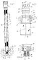
- Fig. 1
- in Seitenansicht, teilweise im Schnitt, eine Trocknerpatrone, beispielsweise in einem gestrichelt angedeuteten Kondensator, jedoch auch brauchbar für einen Trockner- oder Akkumulatorbehälter, einer Fahrzeug-Klimaanlage,
- Fig. 2A
- vergrößert den unteren Endabschnitt der Trocknerpatrone von Fig. 1, teilweise im Schnitt,
- Fig. 2B
- eine Detailvariante zu Fig. 2A,
- Fig. 3
- eine weitere Ausführungsform einer Trocknerpatrone, von der in Explosionsdarstellung der untere Endbereich angedeutet ist,
- Fig. 4
- einen Teilschnitt einer weiteren Ausführungsform, und
- Fig. 5
- einen Schnitt einer weiteren Ausführungsform.
Claims (16)
- Trocknerpatrone (P) für eine Fahrzeug-Klimaanlage, mit einem Kunststoff-Grundkörper (10) in Form eines Rohrabschnittes, der zumindest in der Außenwand fensterartige Durchbrüche aufweist, die mit einem wenigstens eine Exsiccator-Charge (D) einschließenden Filtermaterial (33, 14) abgedeckt sind, mit wenigstens einer Abströmöffnung (13, 13') im unteren Endbereich des Rohrabschnitts, die durch ein Filtermaterial (14) abgedeckt ist, mit einem außen angeordneten, umlaufenden Sitz (15) zwischen den Durchbrüchen und der Abströmöffung, und mit einem im Sitz (15) angeordneten Dichtungsring (R) aus elastischem Material, dadurch gekennzeichnet, daß der Dichtungsring (R) einen in etwa zylindrischen Grundkörper (23) mit mindestens zwei axial beabstandeten, annähernd zueinander parallel umlaufenden und vom Grundkörper (23) nach außen abstehenden, frei endenden, biegsamen Dichtlippen (L, L1 bis L3) aufweist.
- Trocknerpatrone nach Anspruch 1, dadurch gekennzeichnet, daß der Dichtungsring (R) drei Dichtlippen (L1 bis L3) aufweist.
- Trocknerpatrone nach Anspruch 1, dadurch gekennzeichnet, daß der Grundkörper (23) axial über die jeweils endseitige Dichtlippe (L1, L3) übersteht und in etwa bündig mit dem als Ringnut ausgebildeten Sitz (15) abschließt.
- Trocknerpatrone nach Anspruch 1, dadurch gekennzeichnet, daß die Dichtlippen (L, L1 bis L3) in etwa gleiche Höhe aufweisen, die, vorzugsweise ca. 150 % der radialen Dicke des Grundkörpers (23) beträgt.
- Trocknerpatrone nach Anspruch 1, dadurch gekennzeichnet, daß zwischen den Dichtlippen (L, L1 bis L3) in etwa gleiche axiale Abstände vorgesehen sind, vorzugsweise in etwa jeweils 150% der radialen Dicke des Grundkörpers (23) entsprechend.
- Trocknerpatrone nach Anspruch 1, dadurch gekennzeichnet, daß die axiale Stärke jeder Dichtlippe (L, L1 bis L3) in etwa der radialen Dicke des Grundkörpers (23) entspricht.
- Trocknerpatrone nach Anspruch 1, dadurch gekennzeichnet, daß der Kamm jeder Dichtlippe (L, L1 bis L3) gerundet oder schneidenförmig ist.
- Trocknerpatrone nach wenigstens einem der Ansprüche 1 bis 7, dadurch gekennzeichnet, daß der Dichtungsring (R) einstückig aus Gummi oder einem elastomeren Kunststoff, vorzugsweise aus HNBR, z.B. mit einer Shore-Härte um etwa 70, ausgebildet ist.
- Trocknerpatrone nach Anspruch 1, dadurch gekennzeichnet, daß der Rohrabschnitt jenseits des Sitzes (15) für den Dichtungsring (R) einen topfartigen Endteil (18, 18', 18'') entweder mit umfangsseitigen, die Abströmöffnung (13) definierenden, durch das Feinfiltermaterial (14) abgedeckten Fenstern und einen geschlossenen Topfboden (19), oder mit einem inneliegenden Kanal als Abströmöffnung (13') aufweist.
- Trocknerpatrone nach Anspruch 8, dadurch gekennzeichnet, daß der Endteil (18', 18'') mit der Abströmöffnung (13, 13') und dem Sitz (15) einen eigenständigen auf oder in den Rohrabschnitt gesteckten und mit diesem form- und/oder kraftschlüssig verbundenen Formteil (T, T') bildet.
- Trocknerpatrone nach Anspruch 10, dadurch gekennzeichnet, daß der Formteil (T, T') wenigstens ein Rastelement (27), z.B. einen umlaufenden Steg, und der Rohrabschnitt (10) wenigstens ein Gegenrastelement (25), z.B. einen umlaufenden Wulst oder eine Nut, aufweisen, die in gegenseitigem Eingriff stehen.
- Trocknerpatrone nach Anspruch 9, dadurch gekennzeichnet, daß der Dichtungsring (R) in etwa in der Längsmitte der Trocknerpatrone (P) auf dieser angeordnet ist.
- Trocknerpatrone nach Anspruch 12, dadurch gekennzeichnet, daß der Sitz (V) durch einen verjüngten bzw. eingeschnürten Wandbereich (4') zwischen der Zuström- und der Abströmseite (Z, A) einer rohrartigen Innenwand (1') gebildet ist, mit dem mehr als eine der Dichtlippen (L) in Dichteingriff steht.
- Trocknerpatrone nach wenigstens einem der vorhergehenden Ansprüche, dadurch gekennzeichnet, daß oberhalb des Dichtungsringes (R) ein Fang- und Sammelkragen (K) an der Trocknerpatrone (P) angeordnet ist.
- Trocknerpatrone nach Anspruch 9, dadurch gekennzeichnet, daß in dem die Abströmöffnung (13') bildenden, durch das Filtermaterial (14') abgedeckten Kanal an der Stromabseite des Filtermaterials (14') ein Sicherheitselement (33') mit größerer Porengröße als der Porengröße des Filtermaterials (14') festgelegt ist.
- Trocknerpatrone nach Anspruch 15, dadurch gekennzeichnet, daß das Sicherheitselement (33') mit einem Zwischenabstand (29) in Strömungsrichtung stromab des Filtermaterials (14') festgelegt ist.
Applications Claiming Priority (2)
| Application Number | Priority Date | Filing Date | Title |
|---|---|---|---|
| DE29721546U | 1997-12-05 | ||
| DE29721546U DE29721546U1 (de) | 1997-12-05 | 1997-12-05 | Trocknerpatrone für Fahrzeug-Klimaanlage |
Publications (3)
| Publication Number | Publication Date |
|---|---|
| EP0921022A2 true EP0921022A2 (de) | 1999-06-09 |
| EP0921022A3 EP0921022A3 (de) | 2001-10-24 |
| EP0921022B1 EP0921022B1 (de) | 2005-03-02 |
Family
ID=8049556
Family Applications (1)
| Application Number | Title | Priority Date | Filing Date |
|---|---|---|---|
| EP98120327A Expired - Lifetime EP0921022B1 (de) | 1997-12-05 | 1998-10-27 | Trocknerpatrone für Fahrzeugklimaanlage |
Country Status (3)
| Country | Link |
|---|---|
| EP (1) | EP0921022B1 (de) |
| DE (2) | DE29721546U1 (de) |
| ES (1) | ES2238746T3 (de) |
Cited By (5)
| Publication number | Priority date | Publication date | Assignee | Title |
|---|---|---|---|---|
| WO2003081147A1 (de) | 2002-03-23 | 2003-10-02 | Behr Gmbh & Co. | Kältemittelkondensator |
| EP1363086A1 (de) * | 2002-05-15 | 2003-11-19 | Sanden Corporation | Wärmeaustauscher mit einem einen Einsatz aufnehmenden Teil worin der Einsatz federnd abgestützt wird |
| EP1497596A1 (de) * | 2002-04-17 | 2005-01-19 | Flow Dry Technology Ltd | Trocknungsmittelpatrone für einen integrierten verflüssiger/sammler und herstellungsverfahren dafür |
| EP1387134A3 (de) * | 2002-07-31 | 2005-12-21 | Behr GmbH & Co. KG | Trockner für Kältemittelkondensator |
| US9599414B2 (en) | 2010-11-17 | 2017-03-21 | Zhejiang Sanhua Automotive Components Co., Ltd | Liquid reservoir |
Families Citing this family (3)
| Publication number | Priority date | Publication date | Assignee | Title |
|---|---|---|---|---|
| FR2757612B1 (fr) * | 1996-12-23 | 1999-03-05 | Valeo Thermique Moteur Sa | Condenseur a reservoir integre perfectionne, notamment pour un circuit de climatisation de vehicule automobile |
| DE10221968A1 (de) * | 2002-05-17 | 2003-11-27 | Modine Mfg Co | Aufnahmevorrichtung für Trocknungsmittel |
| US8268032B2 (en) | 2008-07-07 | 2012-09-18 | General Electric Company | Gasket for providing a seal between two objects |
Citations (3)
| Publication number | Priority date | Publication date | Assignee | Title |
|---|---|---|---|---|
| DE4402927A1 (de) | 1994-02-01 | 1995-08-03 | Behr Gmbh & Co | Kondensator für eine Klimaanlage eines Fahrzeuges |
| EP0689014A1 (de) | 1994-06-22 | 1995-12-27 | Behr GmbH & Co. | Einsatz für einen Kondensator einer Klimaanlage eines Fahrzeuges |
| DE29700640U1 (de) | 1997-01-15 | 1997-05-22 | Controls Gmbh Deutsche | Fahrzeug-Klimaanlage und Trocknerpatrone für eine Fahrzeug-Klimaanlage |
Family Cites Families (2)
| Publication number | Priority date | Publication date | Assignee | Title |
|---|---|---|---|---|
| US4436623A (en) * | 1982-07-28 | 1984-03-13 | Multiform Desiccants, Inc. | Adsorbent cartridge |
| FR2746908B1 (fr) * | 1996-03-26 | 1998-05-15 | Valeo Thermique Moteur Sa | Reservoir de fluide refrigerant associe a un condenseur |
-
1997
- 1997-12-05 DE DE29721546U patent/DE29721546U1/de not_active Expired - Lifetime
-
1998
- 1998-10-27 EP EP98120327A patent/EP0921022B1/de not_active Expired - Lifetime
- 1998-10-27 ES ES98120327T patent/ES2238746T3/es not_active Expired - Lifetime
- 1998-10-27 DE DE59812611T patent/DE59812611D1/de not_active Expired - Lifetime
Patent Citations (3)
| Publication number | Priority date | Publication date | Assignee | Title |
|---|---|---|---|---|
| DE4402927A1 (de) | 1994-02-01 | 1995-08-03 | Behr Gmbh & Co | Kondensator für eine Klimaanlage eines Fahrzeuges |
| EP0689014A1 (de) | 1994-06-22 | 1995-12-27 | Behr GmbH & Co. | Einsatz für einen Kondensator einer Klimaanlage eines Fahrzeuges |
| DE29700640U1 (de) | 1997-01-15 | 1997-05-22 | Controls Gmbh Deutsche | Fahrzeug-Klimaanlage und Trocknerpatrone für eine Fahrzeug-Klimaanlage |
Non-Patent Citations (1)
| Title |
|---|
| ROLAND BURK: "kondensatormodul fuer kraftfahrzeug-klimaanlagen", ZEITSCHRIFT ATZ, AUTOMOBILTECHNISCHE ZEITSCHRIFT, vol. 97, no. 5, 1995, STUTTGART, pages 304 - 307 |
Cited By (9)
| Publication number | Priority date | Publication date | Assignee | Title |
|---|---|---|---|---|
| WO2003081147A1 (de) | 2002-03-23 | 2003-10-02 | Behr Gmbh & Co. | Kältemittelkondensator |
| DE10213176A1 (de) * | 2002-03-23 | 2003-10-02 | Behr Gmbh & Co | Kältmittelkondensator |
| EP1497596A1 (de) * | 2002-04-17 | 2005-01-19 | Flow Dry Technology Ltd | Trocknungsmittelpatrone für einen integrierten verflüssiger/sammler und herstellungsverfahren dafür |
| EP1497596A4 (de) * | 2002-04-17 | 2006-11-02 | Flow Dry Technology Ltd | Trocknungsmittelpatrone für einen integrierten verflüssiger/sammler und herstellungsverfahren dafür |
| US7275390B2 (en) | 2002-04-17 | 2007-10-02 | Flow Dry Technology, Inc. | Desiccant cartridge for an integrated condenser/receiver and method of making same |
| EP1363086A1 (de) * | 2002-05-15 | 2003-11-19 | Sanden Corporation | Wärmeaustauscher mit einem einen Einsatz aufnehmenden Teil worin der Einsatz federnd abgestützt wird |
| US6935413B2 (en) | 2002-05-15 | 2005-08-30 | Sanden Corporation | Heat exchanger |
| EP1387134A3 (de) * | 2002-07-31 | 2005-12-21 | Behr GmbH & Co. KG | Trockner für Kältemittelkondensator |
| US9599414B2 (en) | 2010-11-17 | 2017-03-21 | Zhejiang Sanhua Automotive Components Co., Ltd | Liquid reservoir |
Also Published As
| Publication number | Publication date |
|---|---|
| EP0921022A3 (de) | 2001-10-24 |
| EP0921022B1 (de) | 2005-03-02 |
| DE29721546U1 (de) | 1998-01-29 |
| DE59812611D1 (de) | 2005-04-07 |
| ES2238746T3 (es) | 2005-09-01 |
Similar Documents
| Publication | Publication Date | Title |
|---|---|---|
| DE1935764C3 (de) | Flüssigkeitsfütereinheit | |
| EP2654918B1 (de) | Flüssigkeitsfilter mit einem filterumgehungsventil und filtereinsatz dafür | |
| EP1137470B1 (de) | Fluidfilter mit gehäusefestem ablassdom | |
| EP0314915B1 (de) | Ölfilter für die Reinigung von Schmieröl | |
| DE112005001921B4 (de) | Verschluß zum hermetischen Abdichten eines Trocknerbehälters | |
| WO2016030419A1 (de) | Filter, der an einen anschlussflansch anbaubar ist, und filtereinsatz | |
| DE60017706T2 (de) | Filterpatrone und Kondensator | |
| DE202005007872U1 (de) | Filtereinrichtung, insbesondere zur Flüssigkeitsfilterung in Brennkraftmaschinen | |
| EP1879679B1 (de) | Filtereinrichtung, insbesondere zur flüssigkeitsfilterung in brennkraftmaschinen | |
| EP3271042A1 (de) | Filtervorrichtung | |
| EP1685889A1 (de) | Filter für Ölwanne | |
| DE19818334A1 (de) | Sicherheitsventil für eine Filtervorrichtung und ein Verfahren zur Befestigung desselben | |
| DE202005007871U1 (de) | Filtereinrichtung, insbesondere zur Flüssigkeitsfilterung in Brennkraftmaschinen | |
| WO1997037743A1 (de) | Filtervorrichtung | |
| DE202005007869U1 (de) | Filtereinrichtung, insbesondere zur Flüssigkeitsfilterung in Brennkraftmaschinen | |
| EP1147930B1 (de) | Kondensator für die Klimaanlage eines Kraftfahrzeuges | |
| DE60020868T2 (de) | Ventilanlage für Fahrzeugspülsystem | |
| DE19925635B4 (de) | Hydraulikölbehälter | |
| EP3854470A1 (de) | Filtereinrichtung und rundfilterelement, insbesondere zur gasfiltration | |
| EP1648583B1 (de) | Ölfilteranordnung und filterelement | |
| DE19828328A1 (de) | Stopfenanordnung zum Verschließen von Löchern in der Karosserie von Fahrzeugen | |
| EP0921022B1 (de) | Trocknerpatrone für Fahrzeugklimaanlage | |
| DE19859960B4 (de) | Flüssigkeitsfilter | |
| EP4017770B1 (de) | Rückschlagventil-vorrichtung | |
| WO2021009094A1 (de) | Fluidfilter für einen kraftwagen und filterkartusche für einen fluidfilter |
Legal Events
| Date | Code | Title | Description |
|---|---|---|---|
| PUAI | Public reference made under article 153(3) epc to a published international application that has entered the european phase |
Free format text: ORIGINAL CODE: 0009012 |
|
| AK | Designated contracting states |
Kind code of ref document: A2 Designated state(s): AT BE CH CY DE DK ES FI FR GB GR IE IT LI LU MC NL PT SE Kind code of ref document: A2 Designated state(s): DE ES FR GB IT |
|
| AX | Request for extension of the european patent |
Free format text: AL;LT;LV;MK;RO;SI |
|
| RAP1 | Party data changed (applicant data changed or rights of an application transferred) |
Owner name: S.K.G. ITALIANA S.P.A. |
|
| PUAL | Search report despatched |
Free format text: ORIGINAL CODE: 0009013 |
|
| AK | Designated contracting states |
Kind code of ref document: A3 Designated state(s): AT BE CH CY DE DK ES FI FR GB GR IE IT LI LU MC NL PT SE |
|
| AX | Request for extension of the european patent |
Free format text: AL;LT;LV;MK;RO;SI |
|
| 17P | Request for examination filed |
Effective date: 20020424 |
|
| AKX | Designation fees paid |
Free format text: DE ES FR GB IT |
|
| RAP1 | Party data changed (applicant data changed or rights of an application transferred) |
Owner name: FINBER S.P.A |
|
| GRAP | Despatch of communication of intention to grant a patent |
Free format text: ORIGINAL CODE: EPIDOSNIGR1 |
|
| GRAS | Grant fee paid |
Free format text: ORIGINAL CODE: EPIDOSNIGR3 |
|
| GRAA | (expected) grant |
Free format text: ORIGINAL CODE: 0009210 |
|
| AK | Designated contracting states |
Kind code of ref document: B1 Designated state(s): DE ES FR GB IT |
|
| REG | Reference to a national code |
Ref country code: GB Ref legal event code: FG4D Free format text: NOT ENGLISH |
|
| GBT | Gb: translation of ep patent filed (gb section 77(6)(a)/1977) |
Effective date: 20050302 |
|
| REF | Corresponds to: |
Ref document number: 59812611 Country of ref document: DE Date of ref document: 20050407 Kind code of ref document: P |
|
| REG | Reference to a national code |
Ref country code: ES Ref legal event code: FG2A Ref document number: 2238746 Country of ref document: ES Kind code of ref document: T3 |
|
| PLBE | No opposition filed within time limit |
Free format text: ORIGINAL CODE: 0009261 |
|
| STAA | Information on the status of an ep patent application or granted ep patent |
Free format text: STATUS: NO OPPOSITION FILED WITHIN TIME LIMIT |
|
| ET | Fr: translation filed | ||
| 26N | No opposition filed |
Effective date: 20051205 |
|
| PGFP | Annual fee paid to national office [announced via postgrant information from national office to epo] |
Ref country code: GB Payment date: 20071018 Year of fee payment: 10 |
|
| GBPC | Gb: european patent ceased through non-payment of renewal fee |
Effective date: 20081027 |
|
| PG25 | Lapsed in a contracting state [announced via postgrant information from national office to epo] |
Ref country code: GB Free format text: LAPSE BECAUSE OF NON-PAYMENT OF DUE FEES Effective date: 20081027 |
|
| REG | Reference to a national code |
Ref country code: FR Ref legal event code: PLFP Year of fee payment: 18 |
|
| REG | Reference to a national code |
Ref country code: FR Ref legal event code: PLFP Year of fee payment: 19 |
|
| PGFP | Annual fee paid to national office [announced via postgrant information from national office to epo] |
Ref country code: DE Payment date: 20161027 Year of fee payment: 19 Ref country code: FR Payment date: 20161022 Year of fee payment: 19 |
|
| PGFP | Annual fee paid to national office [announced via postgrant information from national office to epo] |
Ref country code: ES Payment date: 20161026 Year of fee payment: 19 Ref country code: IT Payment date: 20161031 Year of fee payment: 19 |
|
| REG | Reference to a national code |
Ref country code: DE Ref legal event code: R119 Ref document number: 59812611 Country of ref document: DE |
|
| REG | Reference to a national code |
Ref country code: FR Ref legal event code: ST Effective date: 20180629 |
|
| PG25 | Lapsed in a contracting state [announced via postgrant information from national office to epo] |
Ref country code: DE Free format text: LAPSE BECAUSE OF NON-PAYMENT OF DUE FEES Effective date: 20180501 |
|
| PG25 | Lapsed in a contracting state [announced via postgrant information from national office to epo] |
Ref country code: FR Free format text: LAPSE BECAUSE OF NON-PAYMENT OF DUE FEES Effective date: 20171031 |
|
| PG25 | Lapsed in a contracting state [announced via postgrant information from national office to epo] |
Ref country code: IT Free format text: LAPSE BECAUSE OF NON-PAYMENT OF DUE FEES Effective date: 20171027 |
|
| REG | Reference to a national code |
Ref country code: ES Ref legal event code: FD2A Effective date: 20181221 |
|
| PG25 | Lapsed in a contracting state [announced via postgrant information from national office to epo] |
Ref country code: ES Free format text: LAPSE BECAUSE OF NON-PAYMENT OF DUE FEES Effective date: 20171028 |