EP0920112B1 - Brushless three-phase synchronous generator having enhanced rotor field system - Google Patents
Brushless three-phase synchronous generator having enhanced rotor field system Download PDFInfo
- Publication number
- EP0920112B1 EP0920112B1 EP98306373A EP98306373A EP0920112B1 EP 0920112 B1 EP0920112 B1 EP 0920112B1 EP 98306373 A EP98306373 A EP 98306373A EP 98306373 A EP98306373 A EP 98306373A EP 0920112 B1 EP0920112 B1 EP 0920112B1
- Authority
- EP
- European Patent Office
- Prior art keywords
- windings
- field windings
- field
- phase
- brushless
- Prior art date
- Legal status (The legal status is an assumption and is not a legal conclusion. Google has not performed a legal analysis and makes no representation as to the accuracy of the status listed.)
- Expired - Lifetime
Links
Images

Classifications
-
- H—ELECTRICITY
- H02—GENERATION; CONVERSION OR DISTRIBUTION OF ELECTRIC POWER
- H02K—DYNAMO-ELECTRIC MACHINES
- H02K19/00—Synchronous motors or generators
- H02K19/16—Synchronous generators
- H02K19/26—Synchronous generators characterised by the arrangement of exciting windings
- H02K19/28—Synchronous generators characterised by the arrangement of exciting windings for self-excitation
Definitions
- the present invention relates to a brushless three-phase synchronous generator. More particularly, the present invention relates to a circuit construction of the rotor field windings for use in the brushless three-phase synchronous generator, which is so devised that an improvement is made on waveform of the current flowing in the rotor field windings induced based on the odd-order higher harmonic magnetic fluxes generated by the stator excitation windings and that an enhancement is achieved on the excitation efficiency.
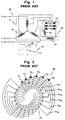
- Fig. 1 shows a circuit diagram of the conventional brushless three-phase synchronous generator 40.
- a stator side 41 there are provided three-phase four-pole primary generating windings 42, stator excitation windings 43 whose number of poles is 12, odd-number times the number of poles of the primary generating windings 42, and a DC power source 44 which is formed by a variable resistor 48 and a plurality of diodes 49.
- a rotor side 45 there are provided a plurality of rotor field windings 46 wound in a full-pitch concentrated winding manner, whose number of poles is the same as that of the primary generating windings 42 of the rotor 41.
- Each of the rotor field windings is short-circuited by a diode 47.
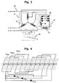
- Fig. 2 shows a further detailed construction of the rotor 45.
- the plurality of field windings W f1 - W f6 (generally shown by numeral 46 in Fig. 1) are wound on a cylindrical field system 20 so as to form a four-pole construction, and the field windings W f1 - W f6 are respectively short-circuited by the corresponding diodes D1 - D6 (generally shown by numeral 47 in Fig. 1).
- the overlapped magnetic fields formed by the armature reaction magnetic field and the static magnetic field cause the electromotive forces to be induced in the plurality of respective field windings 46 of the rotor 45, which field windings are magnetically coupled with all the odd-order spatial higher harmonic components of the armature reaction magnetic fields and the static magnetic fields.
- the electromotive forces thus induced in the field windings are respectively half-wave rectified by the corresponding diodes D1 - D6, and the DC components thus obtained function to increase the field magnetic fluxes of the rotor.
- the electromotive forces induced in the primary generating windings 42 of the stator also increase. In this way, the generated voltage gradually goes up and finally reaches the self-establish maximum voltage at the non-load state.
- the rotor field windings 46 (W f1 - W f6 ) are wound in a full-pitch concentrated winding manner so as to have the same number of poles as that of the primary generating windings 42 of the stator and further they are respectively short-circuited by the corresponding diodes 47 (D1 - D6), they react with all the odd-order spatial higher harmonic components and, therefore, function to increase the field magnetic fluxes of the rotor field windings 46.
- the amplification factor that is, the ratio of the magnetomotive force of the field windings with respect to that of the stator excitation windings is small and, thus, the capacitor required to the automatic voltage regulator (AVR) inevitably becomes large. For this reason, there has been a demand for developing an improved generator having high excitation efficiency in which the amplification factor of the magnetomotive forces is large and by which the capacitor of the automatic voltage regulator can be reduced.
- An object of the present invention is to overcome the problems existing in the prior art generator, and to provide a brushless three-phase synchronous generator wherein the magnetic coupling of the rotor field windings of the full-pitch concentrated form with respect to the spatial higher harmonic components of the armature reaction magnetic fields is maintained well.
- a brushless three-phase synchronous generator which comprises a stator including primary generating windings and stator excitation windings having the number of poles odd-number times the number of poles of the primary generating windings, and a rotor including a cylindrical field system which is magnetically coupled with the primary generating windings, the synchronous generator comprising:
- the rectifier means may be a plurality of diodes each connected in series with each of the plurality of predetermined field windings other than the central field windings.
- the rectifier means may be at least one diode connected in series with the plurality of predetermined field windings other than the central field windings, the plurality of predetermined field windings forming an AC component loop circuit.
- the circulating means may be constituted by diodes.
- Figs. 3, 4, 5 and 6 show a first embodiment of the brushless three-phase synchronous generator 70 according to the invention.
- Fig. 3 shows a circuit diagram of the generator 70 according to the invention.
- the difference of the generator 70 of the present invention from the conventional one 40 shown in Fig. 1 resides only at the rotor side 60.
- Fig. 4 shows a circuit diagram of one set, among three sets in total, of the field windings of the rotor.
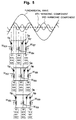
- Fig. 5 is a further detailed diagram showing the connection of the three sets of the plurality of rotor windings W f51 - W f59 .
- Fig. 6 shows a graph showing the currents in the field windings of the generator according to the present invention and those of the conventional generator.
- the stator side 41 of the generator 70 according to the present invention is the same as that of the conventional one.
- the stator 41 comprises primary generating windings 42 of three-phase four-pole, stator excitation windings 43 whose number of poles is 12, the odd-number times the number of poles of the primary generating windings 42, and a DC power source 44 which has a plurality of three-phase bridge-connection diodes 49 and a variable resistor 48.
- the rotor side 60 there are wound a plurality of rotor field windings 50 in the full-pitch concentrated winding form, which windings have the same number of poles as that of the primary generating windings 42. In this example, the number of poles is four.
- the rotor field windings 46 are respectively short-circuited by the corresponding diodes 47 (D1 - D7)
- the rotor field windings 50 of the generator 70 according to the present invention are connected as shown in Fig. 4.
- Explanation for the rotor of the embodiments is made hereunder on the assumption that the number of slots provided in the rotor core is thirty six (36) and the field windings are wound therein so as to be of four (4) poles.
- Nine (9) slots per one pole are assigned on the rotor core.
- One set of the field windings are wound on twelve slots over four poles. There are provided three sets, in total, of such set of field windings on the rotor core.
- FIG. 5 there are wound, on the cylindrical rotor core, nine field windings W f51 - W f59 (generally represented by numeral 50 in Fig. 3) in the full-pitch concentrated winding form so as to be four poles, through the semiconductor elements D11 - D19.
- the field windings W f51 and W f57 in which the same phase voltages are induced by the third-order spatial harmonic magnetic field are connected in parallel and, then, further connected in parallel to the central field windings W f54 which function to effectively produce primary field magnetic fluxes.
- the term used for "central field windings" is to represent the field windings which produce greater magnetic fluxes than other field windings when producing primary field magnetic fluxes.
- the field windings W f52 and W f58 connected in parallel are further connected in parallel to the central field windings W f55
- the field windings W f53 and W f59 connected in parallel are further connected in parallel to the central field windings W f56 .
- the semiconductor elements D11 - D19 are generally such rectifier means as diodes.
- Fig. 5 shows the positional relationships of the field windings W f51 - W f59 wound in the slots S1 - S36 of the rotor with respect to the phases of the spatial fundamental wave of the static magnetic field, the third-order spatial harmonic component and the fifth-order spatial harmonic component of the armature reaction magnetic field.
- the field windings W f51 and W f57 in which the voltages of the same phase are induced based on the third-order spatial harmonic magnetic field, among the plurality of the full-pitch concentrated field windings, are connected in parallel with each other and then further connected in parallel to the central field windings W f54 in which the voltage of the opposite-phase is induced.
- the overlapped magnetic fields formed by the armature reaction magnetic fields and the static magnetic field cause the electromotive forces to be induced in the respective field windings 50 of the rotor 60, which windings are magnetically coupled with all the odd-order spatial higher harmonic components of the armature reaction magnetic fields and the static magnetic fields.
- the electromotive forces thus induced in the field windings 50 are respectively half-wave rectified by the corresponding diodes D11 - D19, and the DC components thus obtained increase the primary field magnetic fluxes of the rotor.
- the electromotive forces induced in the primary generating windings 42 of the stator also increase. In this way, the voltage at the non-load state is self-established.
- the operation up to here explained above is the same as that in the conventional generator.
- the field windings W f51 and W f57 in which the voltages of the same phase are induced are connected in parallel through the respective corresponding diodes D11 and D17 (DC conversion circuit).
- the parallel-connected field windings W f51 and W f57 are further connected in parallel to the central field windings W f54 which function to effectively produce the primary field magnetic fluxes.
- a circulating means D14 such as a diode is connected in parallel to the central field windings W f54 .
- the currents flowing in the field windings W f51 and W f57 are respectively half-wave rectified by the corresponding diodes D11 and D17 and, the DC components thus obtained flow into the central field windings W f54 which function to effectively produce the primary field magnetic fluxes. Due to the above DC components together with the function of the circulating diode D14, there flows a current having relatively large amount of DC components in the central field windings W f54 , so that there is an increase in the primary field magnetic fluxes due to the increase in the magnetomotive forces. As a result, as shown in Fig.
- the amount of current flowing in the central field windings W f54 greatly increase and the waveform of the current in the field windings is greatly smoothed due to the increase in the DC components. Hence, due to the increase of the magnetomotive forces, improvement of the efficiency of the generator can be effectively achieved.
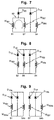
- Fig. 7 shows a second embodiment of the field winding circuit according to the present invention.
- the field windings W f51 and W f57 in which the same phase voltages are induced therein are firstly directly connected in parallel so that an AC component loop circuit 80 is formed and, then, they are connected in parallel to the central field windings W f54 through a diode D20.
- a plurality of the field windings of the same phase which are directly connected in parallel are further connected in parallel to the central field windings through at least one common diode D20.
- the AC component loop circuit 80 in this embodiment there flows a circulating current between the field windings concerned since the phase difference of currents flowing therein based on the fundamental wave component of the opposite-phase rotating magnetic field in the case where the single-phase load is connected to the generator, becomes 120 degrees.
- the rectified current flowing into the central field windings W f54 through the diode D20 decreases, the field magnetic fluxes produced by the same windings W f54 decreases accordingly and, hence, the output voltage is prevented from excessively rising up.
- Fig. 8 shows a third embodiment of the field winding circuit according to the present invention.
- the field windings W f52 and W f59 in which the voltages of the same phase are induced but the above phase is different in predetermined degrees from the phase of the voltage induced in the central field windings W f54 by the odd-order spatial higher harmonic magnetic fields are connected in parallel through the corresponding diodes D12, D14.
- the parallel-connected field windings W f52 and W f59 are further connected in parallel to the central field windings W f54 to which a circulating diode D14 is connected.
- the current to flow in the central field windings W f54 increases and further its waveforms are greatly smoothed.
- this third embodiment enables the phase difference to be zero at the time when the load is actually applied to the generator though there exists a phase difference at the time when no load is applied thereto.
- the brushless three-phase synchronous generator of the this third embodiment may also have an AC component loop circuit which is formed by the field windings W f52 and W f59 .
- the AC component having double frequency which develops in the field windings based on the interlinkage with the opposite-phase rotating magnetic fields at the time when the single-phase load is applied to the generator, can be absorbed by the loop circuit, the disturbance of the current waveforms caused by the AC component can be prevented, and the abnormal high voltage caused by the self-excitation phenomenon of the rotor field windings because of its function as damper windings can be prevented from occurring.
- Fig. 9 shows a further embodiment according to the present invention wherein the central field windings W f54 are divided into two sub-divided central field windings W f54a and W f54b , one for being connected to the field windings W f51 and the other for being connected to the field windings W f57 .
- This embodiment is particularly advantageous in the case where an interference is expected to occur between the slot S1 (the field windings W f51 being provided therein) and the slot S7 (the field windings W f57 being provided therein).
- the currents flowing in the field windings which do not effectively produce field magnetic fluxes are half-wave rectified by diodes and, then, the currents of DC component thus obtained are caused to collectively flow into the central field windings which effectively produce primary field magnetic fluxes, the current of DC component flowing in the central field windings increases and its current waveforms are greatly smoothed.
- the field magnetomotive forces become large and the excitation efficiency is improved, whereby the efficiency of the generator is significantly enhanced.
- the loop circuit which is formed by directly connecting at least two field windings in parallel and which is for absorbing the AC component of the double frequency that is generated based on the interlinkage with the opposite-phase rotating magnetic field at the time when the single-phase load is connected to the generator, the disturbance of the current waveforms caused by the AC components can be effectively prevented and the excessive high voltage based on the self-excitation phenomenon because of the rotor field windings' function as damper windings can be prevented from generated.
Landscapes
- Engineering & Computer Science (AREA)
- Power Engineering (AREA)
- Synchronous Machinery (AREA)
Applications Claiming Priority (6)
| Application Number | Priority Date | Filing Date | Title |
|---|---|---|---|
| JP344226/97 | 1997-11-28 | ||
| JP34422697 | 1997-11-28 | ||
| JP34422697 | 1997-11-28 | ||
| JP127977/98 | 1998-05-11 | ||
| JP12797798A JP3788494B2 (ja) | 1997-11-28 | 1998-05-11 | ブラシレス三相同期発電機 |
| JP12797798 | 1998-05-11 |
Publications (2)
| Publication Number | Publication Date |
|---|---|
| EP0920112A1 EP0920112A1 (en) | 1999-06-02 |
| EP0920112B1 true EP0920112B1 (en) | 2002-01-02 |
Family
ID=26463783
Family Applications (1)
| Application Number | Title | Priority Date | Filing Date |
|---|---|---|---|
| EP98306373A Expired - Lifetime EP0920112B1 (en) | 1997-11-28 | 1998-08-10 | Brushless three-phase synchronous generator having enhanced rotor field system |
Country Status (5)
| Country | Link |
|---|---|
| US (1) | US6130492A (zh) |
| EP (1) | EP0920112B1 (zh) |
| JP (1) | JP3788494B2 (zh) |
| CN (1) | CN1118921C (zh) |
| DE (1) | DE69803353T2 (zh) |
Families Citing this family (12)
| Publication number | Priority date | Publication date | Assignee | Title |
|---|---|---|---|---|
| CN100454726C (zh) * | 2001-11-27 | 2009-01-21 | 泰豪科技股份有限公司 | 大容量单相无刷同步发电机 |
| JP2006174692A (ja) * | 2004-11-19 | 2006-06-29 | Nippon Densan Corp | ブラシレスモータ |
| JP5302527B2 (ja) | 2007-10-29 | 2013-10-02 | 株式会社豊田中央研究所 | 回転電機及びその駆動制御装置 |
| JP2009112169A (ja) * | 2007-10-31 | 2009-05-21 | Honda Motor Co Ltd | 発電機の出力制御装置 |
| FR2949176B1 (fr) * | 2009-08-14 | 2011-09-16 | Leroy Somer Moteurs | Machine electrique tournante comportant une excitatrice |
| US8008827B1 (en) * | 2010-02-18 | 2011-08-30 | Tesla Motors, Inc. | Triple layer winding pattern and methods of manufacturing same |
| DE102010041034A1 (de) | 2010-09-20 | 2012-03-22 | Robert Bosch Gmbh | Verfahren zum Umladen von Energie zwischen mindestens zwei Energiespeicherzellen in einem steuerbaren Energiespeicher |
| DE102010041068A1 (de) | 2010-09-20 | 2012-03-22 | Robert Bosch Gmbh | System zum Laden eines Energiespeichers und Verfahren zum Betrieb des Ladesystems |
| US10075051B2 (en) | 2015-03-16 | 2018-09-11 | Foster-Miller, Inc. | Series-wound heteropolar inductor motor |
| CN105207555B (zh) * | 2015-09-18 | 2018-03-09 | 重庆铭贝科技有限公司 | 一种数字式发电机自动调节系统及其方法 |
| CN110401387A (zh) * | 2019-08-13 | 2019-11-01 | 福建凯威斯发电机有限公司 | 一种双频率切换发电机 |
| TW202141064A (zh) | 2020-03-24 | 2021-11-01 | 日商索尼半導體解決方案公司 | 受光裝置及測距裝置 |
Family Cites Families (5)
| Publication number | Priority date | Publication date | Assignee | Title |
|---|---|---|---|---|
| JPS583554A (ja) * | 1981-06-26 | 1983-01-10 | Fukuo Shibata | ブラシなし同期機の構造 |
| DE3669816D1 (de) * | 1985-07-04 | 1990-04-26 | Bbc Brown Boveri & Cie | Drehstromerreger fuer synchronmaschinen. |
| US4851758A (en) * | 1987-03-09 | 1989-07-25 | Sawafuji Electric Co., Ltd. | Brushless generator |
| JPH0787717A (ja) * | 1993-09-18 | 1995-03-31 | Satake Eng Co Ltd | ブラシレス同期発電機 |
| JP3489105B2 (ja) * | 1994-08-11 | 2004-01-19 | 株式会社サタケ | ブラシレス自励三相同期発電機 |
-
1998
- 1998-05-11 JP JP12797798A patent/JP3788494B2/ja not_active Expired - Fee Related
- 1998-08-10 EP EP98306373A patent/EP0920112B1/en not_active Expired - Lifetime
- 1998-08-10 DE DE69803353T patent/DE69803353T2/de not_active Expired - Fee Related
- 1998-09-16 US US09/154,091 patent/US6130492A/en not_active Expired - Fee Related
- 1998-11-27 CN CN98122944A patent/CN1118921C/zh not_active Expired - Fee Related
Also Published As
| Publication number | Publication date |
|---|---|
| JPH11220857A (ja) | 1999-08-10 |
| DE69803353T2 (de) | 2002-09-19 |
| EP0920112A1 (en) | 1999-06-02 |
| US6130492A (en) | 2000-10-10 |
| CN1222781A (zh) | 1999-07-14 |
| DE69803353D1 (de) | 2002-02-28 |
| CN1118921C (zh) | 2003-08-20 |
| JP3788494B2 (ja) | 2006-06-21 |
Similar Documents
| Publication | Publication Date | Title |
|---|---|---|
| US5694027A (en) | Three-phase brushless self-excited synchronous generator with no rotor excitation windings | |
| CA1163665A (en) | Polyphase electric machine having controlled magnetic flux density | |
| CA1164933A (en) | Variable speed electric machine having controlled magnetic flux density | |
| US4851758A (en) | Brushless generator | |
| EP0920112B1 (en) | Brushless three-phase synchronous generator having enhanced rotor field system | |
| US20240006967A1 (en) | Field winding type rotating electric machine | |
| US5598091A (en) | Three-phase brushless self-excited synchronous generator with no rotor exciting windings | |
| US5796233A (en) | Multiple-stator induction synchronous motor | |
| US4954740A (en) | Stator winding for two-speed electrodynamic machines having fractional speed ratios | |
| US4656410A (en) | Construction of single-phase electric rotating machine | |
| JPH04347566A (ja) | ブラシレス同期機 | |
| JP2939914B2 (ja) | ブラシレス自励同期発電機 | |
| US5731971A (en) | Apparatus for providing multiple, phase-shifted power outputs | |
| JP3539148B2 (ja) | 円筒型同期発電機 | |
| JPH03245755A (ja) | ブラシレス自励同期発電機 | |
| JP2003088177A (ja) | 多重pwmインバータによる電動機駆動方式 | |
| Li et al. | Switched reluctance motor drives with fractionally-pitched winding design | |
| US3868564A (en) | Synchronous electric machine | |
| JP2020022300A (ja) | 6相交流発電機、3相−6相変換トランス、および直流給電システム | |
| JPS6223348A (ja) | ブラシレス発電機 | |
| JP2753721B2 (ja) | ブラシレス自励同期発電機 | |
| JPH0724930Y2 (ja) | ブラシレス単相交流発電機 | |
| JPH06269151A (ja) | ブラシレス同期発電機 | |
| JPH0817560B2 (ja) | ブラシレス発電機 | |
| Subbiah et al. | Certain design aspects of single-winding three-phase inductor alternators |
Legal Events
| Date | Code | Title | Description |
|---|---|---|---|
| PUAI | Public reference made under article 153(3) epc to a published international application that has entered the european phase |
Free format text: ORIGINAL CODE: 0009012 |
|
| AK | Designated contracting states |
Kind code of ref document: A1 Designated state(s): DE FR GB IT |
|
| AX | Request for extension of the european patent |
Free format text: AL;LT;LV;MK;RO;SI |
|
| 17P | Request for examination filed |
Effective date: 19990625 |
|
| AKX | Designation fees paid |
Free format text: DE FR GB IT |
|
| GRAG | Despatch of communication of intention to grant |
Free format text: ORIGINAL CODE: EPIDOS AGRA |
|
| 17Q | First examination report despatched |
Effective date: 20010215 |
|
| GRAG | Despatch of communication of intention to grant |
Free format text: ORIGINAL CODE: EPIDOS AGRA |
|
| GRAH | Despatch of communication of intention to grant a patent |
Free format text: ORIGINAL CODE: EPIDOS IGRA |
|
| GRAH | Despatch of communication of intention to grant a patent |
Free format text: ORIGINAL CODE: EPIDOS IGRA |
|
| GRAA | (expected) grant |
Free format text: ORIGINAL CODE: 0009210 |
|
| REG | Reference to a national code |
Ref country code: GB Ref legal event code: IF02 |
|
| AK | Designated contracting states |
Kind code of ref document: B1 Designated state(s): DE FR GB IT |
|
| REF | Corresponds to: |
Ref document number: 69803353 Country of ref document: DE Date of ref document: 20020228 |
|
| ET | Fr: translation filed | ||
| PLBE | No opposition filed within time limit |
Free format text: ORIGINAL CODE: 0009261 |
|
| STAA | Information on the status of an ep patent application or granted ep patent |
Free format text: STATUS: NO OPPOSITION FILED WITHIN TIME LIMIT |
|
| 26N | No opposition filed | ||
| PGFP | Annual fee paid to national office [announced via postgrant information from national office to epo] |
Ref country code: FR Payment date: 20060808 Year of fee payment: 9 |
|
| PGFP | Annual fee paid to national office [announced via postgrant information from national office to epo] |
Ref country code: IT Payment date: 20060831 Year of fee payment: 9 |
|
| PGFP | Annual fee paid to national office [announced via postgrant information from national office to epo] |
Ref country code: DE Payment date: 20070809 Year of fee payment: 10 |
|
| PGFP | Annual fee paid to national office [announced via postgrant information from national office to epo] |
Ref country code: GB Payment date: 20070809 Year of fee payment: 10 |
|
| REG | Reference to a national code |
Ref country code: FR Ref legal event code: ST Effective date: 20080430 |
|
| PG25 | Lapsed in a contracting state [announced via postgrant information from national office to epo] |
Ref country code: FR Free format text: LAPSE BECAUSE OF NON-PAYMENT OF DUE FEES Effective date: 20070831 |
|
| GBPC | Gb: european patent ceased through non-payment of renewal fee |
Effective date: 20080810 |
|
| PG25 | Lapsed in a contracting state [announced via postgrant information from national office to epo] |
Ref country code: DE Free format text: LAPSE BECAUSE OF NON-PAYMENT OF DUE FEES Effective date: 20090303 |
|
| PG25 | Lapsed in a contracting state [announced via postgrant information from national office to epo] |
Ref country code: IT Free format text: LAPSE BECAUSE OF NON-PAYMENT OF DUE FEES Effective date: 20070810 |
|
| PG25 | Lapsed in a contracting state [announced via postgrant information from national office to epo] |
Ref country code: GB Free format text: LAPSE BECAUSE OF NON-PAYMENT OF DUE FEES Effective date: 20080810 |