EP0920069A1 - Filtre en forme de peigne comprenant une ligne à constantes distribuées - Google Patents
Filtre en forme de peigne comprenant une ligne à constantes distribuées Download PDFInfo
- Publication number
- EP0920069A1 EP0920069A1 EP98122249A EP98122249A EP0920069A1 EP 0920069 A1 EP0920069 A1 EP 0920069A1 EP 98122249 A EP98122249 A EP 98122249A EP 98122249 A EP98122249 A EP 98122249A EP 0920069 A1 EP0920069 A1 EP 0920069A1
- Authority
- EP
- European Patent Office
- Prior art keywords
- comb
- electrode
- line
- distributed constant
- grounding
- Prior art date
- Legal status (The legal status is an assumption and is not a legal conclusion. Google has not performed a legal analysis and makes no representation as to the accuracy of the status listed.)
- Withdrawn
Links
Images


Classifications
-
- H—ELECTRICITY
- H01—ELECTRIC ELEMENTS
- H01P—WAVEGUIDES; RESONATORS, LINES, OR OTHER DEVICES OF THE WAVEGUIDE TYPE
- H01P1/00—Auxiliary devices
- H01P1/20—Frequency-selective devices, e.g. filters
- H01P1/201—Filters for transverse electromagnetic waves
- H01P1/203—Strip line filters
-
- H—ELECTRICITY
- H01—ELECTRIC ELEMENTS
- H01P—WAVEGUIDES; RESONATORS, LINES, OR OTHER DEVICES OF THE WAVEGUIDE TYPE
- H01P1/00—Auxiliary devices
- H01P1/20—Frequency-selective devices, e.g. filters
- H01P1/201—Filters for transverse electromagnetic waves
- H01P1/203—Strip line filters
- H01P1/20327—Electromagnetic interstage coupling
- H01P1/20336—Comb or interdigital filters
-
- H—ELECTRICITY
- H01—ELECTRIC ELEMENTS
- H01P—WAVEGUIDES; RESONATORS, LINES, OR OTHER DEVICES OF THE WAVEGUIDE TYPE
- H01P7/00—Resonators of the waveguide type
- H01P7/08—Strip line resonators
-
- H—ELECTRICITY
- H01—ELECTRIC ELEMENTS
- H01P—WAVEGUIDES; RESONATORS, LINES, OR OTHER DEVICES OF THE WAVEGUIDE TYPE
- H01P7/00—Resonators of the waveguide type
- H01P7/08—Strip line resonators
- H01P7/082—Microstripline resonators
Definitions
- the present invention relates to a comb-line filter including a distributed constant line. More particularly, the present invention relates to a comb-line filter including a distributed constant line for used in a RF stage of a mobile communication apparatus.
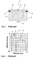
- Fig. 7 shows an example of a conventional comb-line filter including a distributed constant line.
- the comb-line filter 1 is composed of an input electrode 5, an output electrode 6, and microstrip-line resonators 3 and 4 each comprising a distributed constant line, the length of which is approximately one fourth of the wavelength of an intended frequency, one end of which is used as an open end, and the other end of which is used as a grounding end.
- the grounding end is connected to a first grounding electrode 2.
- the two resonators 3 and 4 meanderingly bent are closely arranged side by side so that the linear portion on the side of the grounding end of each of the resonators connected to the grounding electrode 2 is coupled to each other, and the open end of each of the resonators is connected to the input electrode 5 and the output electrode 6 respectively through pairs of comb-like electrodes 7 and 8 made up of two mated comb-like electrodes facing each other. Also, the input electrode 5 and the output electrode 6 are connected through a pair of comb-like electrodes 9 made up of two similarly mated comb-like electrodes facing each other.
- the comb-line filter including a distributed constant line 1 is provided, for example, on the front surface of a dielectric substrate on the total back surface of which a grounding electrode is formed, and the input electrode 5 and the output electrode 6 are connected to an external circuit, for example, by wire bonding.
- a signal input through the input electrode 5 is input into a resonance circuit made up of the microstrip-line resonators 3 and 4 through a capacitance for attenuation pole formed by a pair of comb-like electrodes 7, and only frequencies close to an intended frequency resonate and signals of other frequencies are reflected.
- a resonant signal in the resonance circuit made up of the microstrip-line resonators 3 and 4 is output from the output electrode 6 through a capacitance formed by the pair of comb-like electrodes 8.
- the comb-line filter including a distributed constant line 1 functions as a band-pass filter.
- FIG. 8 the passing characteristic of the comb-line filter including a distributed constant line 1 is shown.
- Characteristic x shows an insertion loss and a band-pass characteristic in which the insertion loss is decreased in the pass-band a around 2 GHz. Further, the portions having the insertion losses increased on the both sides of the pass-band a are caused by a capacitance for attenuation pole which is formed by the pair of comb-like electrodes 9 in Fig. 7.
- the present invention is intended to solve the above-mentioned problem, and presents a comb-line filter including a distributed constant line having an attenuation value increased in the rejection band.
- a preferred embodiment of the present invention provides a comb-line filter including a distributed constant line, comprising: a plurality of resonators each comprising said distributed constant line having an open end and a grounding end; a first grounding electrode connected to each of said grounding end of said resonators; at least two of said resonators put in proximity to each other and arranged side by side; an input electrode and an output electrode respectively capacitance-coupled to two of said open ends of said resonators which are located the farthest from each other; and a second grounding electrode capacitance-coupled to said input electrode and said output electrode threrebetween.
- the above described comb-line filter is able to have a larger attenuation value in the rejection band.
- said second grounding electrode and said input electrode and output electrode may be arranged in proximity to each other. Or, they may be arranged through a pair of comb-like electrodes comprising two mated comb-like electrodes facing each other respectively. Or, They may be arranged through a pair of MIM electrodes comprising two plane shaped electrodes sandwiching an insulating material therebetween.
- Fig. 1 one preferred embodiment of a comb-line filter including a distributed constant line according to the present invention is shown.
- the portions identical or equivalent to those in Fig. 7 are given the same reference numerals and their explanation is omitted.
- the comb-line filter 10 has a second grounding electrode 11, and one end 11a of the second grounding electrode 11 is protruded toward the side of an input electrode 5 and arranged close to the input electrode 5 through a gap 12. Also, the other end 11b of the second grounding electrode 11 is protruded toward the side of an output electrode 6 and arranged close to the output electrode 6 through a gap 13. In this way, by giving the grounding electrode 11 in proximity to the input electrode 5 and the output electrode 6, a grounding capacitance is formed therebetween.
- FIG. 2 shows the passing characteristic of the comb-line filter 10 in Fig. 2.
- Fig. 2 shows the insertion loss, and the portions identical or equivalent to those in Fig. 8 are given the same reference numerals and their explanation is omitted.
- the characteristic x shows the insertion loss of a comb-line filter 1 of a conventional example
- the characteristic y shows the insertion loss of a comb-line filter 10 according to the present invention.
- the characteristic y has an attenuation value of nearly 28 dB, or nearly 10 dB larger than that of the characteristic x, that is, the characteristic y has been improved.
- the attenuation value in the rejection band b can be improved.
- the second grounding electrode 11 is arranged close to the input electrode 5 and output electrode 6 only at one end 11a and the other end 11b of the second electrode 11 to provide a grounding capacitance, but as shown in a comb-line filter 20 including a distributed constant line, the entire portion of a second grounding electrode 21 of a nearly rectangular form can be provided close to the input electrode 5 and output electrode 6.
- the capacitance between the input electrode 5 and output electrode 6 and the second grounding electrode 21 can be made larger, and therefore the attenuation value in the rejection band b is able to be further increased.
- the portions identical or equivalent those in Fig. 1 are given the same reference numerals and their explanation is omitted.
- Fig. 1 the input electrode 5 and the output electrode 6 are connected through a capacitance for attenuation pole formed by a pair of comb-like electrodes 9 made up of two mated comb-like electrodes facing each other, but as shown in a comb-line filter 30 including a distributed constant line in Fig. 4, it is possible to eliminate the portion connecting the input electrode 5 and the output electrode 6 which forms a capacitance for attenuation pole. And in this case, the same working-effect as in Fig. 1 is shown also. More, in Fig. 4, the portions identical or equivalent to those in Fig. 1 are given the same reference numerals, and their explanation is omitted.
- FIG. 5 further another embodiment of a comb-line filter including a distributed constant line according to the present invention is shown.
- the portions identical or equivalent to those in Fig. 1 are given the same reference numerals and their explanation is omitted.
- one end 11a protruded toward the side of an input electrode 5, of the second grounding electrode 11 of the comb-line filter including a distributed constant line 40 and the input electrode 5 are connected through a pair of comb-like electrodes 41 made up of two mated comb-like electrodes facing each other.
- the other end 11b protruded toward the side of an output electrode 6, of the second grounding electrode 11 and the output electrode 6 are connected through a pair of comb-like electrodes 42 made up of two mated comb-like electrodes facing each other.
- FIG. 6 further another embodiment of a comb-line filter including a distributed constant line according to the present invention is shown.
- the portions identical or equivalent to those in Fig. 1 are given the same reference numerals, and their explanation is omitted.
- one end 11a protruded toward the side of an input electrode 5, of a second grounding electrode 11 of the comb-line filter 50 including a distributed constant line and the input electrode 5 are connected through a pair of MIM electrodes made up of two plane electrodes laid one on top of the other and sandwiching an insulating material 51a therebetween.
- MIM is the abbreviation of metal insulator metal and shows the construction of two metal layers sandwiching one insulator layer to form a capacitance.
- the comb-line filter 50 is able to have a large grounding capacitance in the same manner as the comb-line filter 40 in Fig. 5, it is possible to make the attenuation value increased in the rejection band or to make the second grounding electrode small-sized.
- the comb-line filter including a distributed constant line was composed of two microstrip-line resonators each comprising a distributed constant line, but the number of microstrip-line resonators is not limited to two and three or more microstrip-line resonators can be also used for construction.
- microstrip-line resonators were meanderingly bent, but these can take a different form such as a linear form, a spiral form, etc.
- microstrip-line resonators each comprising a distributed constant line were used, but another distributed constant line such as a stripline resonator can be also used.
Landscapes
- Physics & Mathematics (AREA)
- Electromagnetism (AREA)
- Control Of Motors That Do Not Use Commutators (AREA)
Applications Claiming Priority (2)
| Application Number | Priority Date | Filing Date | Title |
|---|---|---|---|
| JP9324655A JPH11163602A (ja) | 1997-11-26 | 1997-11-26 | 分布定数線路型フィルタ |
| JP324655/97 | 1997-11-26 |
Publications (1)
| Publication Number | Publication Date |
|---|---|
| EP0920069A1 true EP0920069A1 (fr) | 1999-06-02 |
Family
ID=18168261
Family Applications (1)
| Application Number | Title | Priority Date | Filing Date |
|---|---|---|---|
| EP98122249A Withdrawn EP0920069A1 (fr) | 1997-11-26 | 1998-11-23 | Filtre en forme de peigne comprenant une ligne à constantes distribuées |
Country Status (3)
| Country | Link |
|---|---|
| EP (1) | EP0920069A1 (fr) |
| JP (1) | JPH11163602A (fr) |
| KR (1) | KR100319787B1 (fr) |
Families Citing this family (1)
| Publication number | Priority date | Publication date | Assignee | Title |
|---|---|---|---|---|
| TWI715478B (zh) * | 2020-03-30 | 2021-01-01 | 財團法人工業技術研究院 | 濾波器 |
Citations (3)
| Publication number | Priority date | Publication date | Assignee | Title |
|---|---|---|---|---|
| US3451015A (en) * | 1966-03-21 | 1969-06-17 | Gen Dynamics Corp | Microwave stripline filter |
| DE4140299A1 (de) * | 1991-10-26 | 1993-07-08 | Aeg Mobile Communication | Kammleitungsfilter |
| EP0641035A2 (fr) * | 1993-08-24 | 1995-03-01 | Matsushita Electric Industrial Co., Ltd. | Duplexeur stratifié d'antenne et filtre diélectrique |
-
1997
- 1997-11-26 JP JP9324655A patent/JPH11163602A/ja active Pending
-
1998
- 1998-11-23 EP EP98122249A patent/EP0920069A1/fr not_active Withdrawn
- 1998-11-26 KR KR1019980050901A patent/KR100319787B1/ko not_active IP Right Cessation
Patent Citations (3)
| Publication number | Priority date | Publication date | Assignee | Title |
|---|---|---|---|---|
| US3451015A (en) * | 1966-03-21 | 1969-06-17 | Gen Dynamics Corp | Microwave stripline filter |
| DE4140299A1 (de) * | 1991-10-26 | 1993-07-08 | Aeg Mobile Communication | Kammleitungsfilter |
| EP0641035A2 (fr) * | 1993-08-24 | 1995-03-01 | Matsushita Electric Industrial Co., Ltd. | Duplexeur stratifié d'antenne et filtre diélectrique |
Non-Patent Citations (1)
| Title |
|---|
| WEN-TENG LO ET AL: "K-BAND QUASI-PLANAR TAPPED COMBLINE FILTER AND DIPLEXER", IEEE TRANSACTIONS ON MICROWAVE THEORY AND TECHNIQUES, vol. 41, no. 2, 1 February 1993 (1993-02-01), pages 215 - 223, XP000361234 * |
Also Published As
| Publication number | Publication date |
|---|---|
| KR100319787B1 (ko) | 2002-03-08 |
| JPH11163602A (ja) | 1999-06-18 |
| KR19990045595A (ko) | 1999-06-25 |
Similar Documents
| Publication | Publication Date | Title |
|---|---|---|
| US6577211B1 (en) | Transmission line, filter, duplexer and communication device | |
| US3451015A (en) | Microwave stripline filter | |
| KR100397758B1 (ko) | 듀플렉서 | |
| US5825263A (en) | Low radiation balanced microstrip bandpass filter | |
| US7276995B2 (en) | Filter | |
| US7978027B2 (en) | Coplanar waveguide resonator and coplanar waveguide filter using the same | |
| US6373352B1 (en) | Duplexer with stepped impedance resonators | |
| EP0961337B1 (fr) | Filtre à haute fréquence du type résonateur à demi-longeur d' onde | |
| JPH11312903A (ja) | 誘電体フィルタ、誘電体デュプレクサ、通信機装置 | |
| JPH1013105A (ja) | 高周波フィルタ | |
| KR100449226B1 (ko) | 유전체 듀플렉서 | |
| JP3071528B2 (ja) | 誘電体フィルタ | |
| JP4113196B2 (ja) | マイクロ波フィルタ | |
| EP0920069A1 (fr) | Filtre en forme de peigne comprenant une ligne à constantes distribuées | |
| US6249195B1 (en) | Dielectric filter, dielectric duplexer, and transceiver having circular and polygonal electrode openings | |
| JP3603826B2 (ja) | スパイラル線路集合体素子、共振器、フィルタ、デュプレクサおよび高周波回路装置 | |
| JP4501729B2 (ja) | 高周波フィルタ | |
| US6828880B2 (en) | Bandpass filter | |
| JP3750420B2 (ja) | 平面フィルタおよびそれを用いたデュプレクサおよびそれらを用いた高周波モジュールおよびそれを用いた通信装置 | |
| JPH11312902A (ja) | 誘電体フィルタ、送受共用器および通信機 | |
| US6850131B2 (en) | Bandpass filter | |
| EP0568370B1 (fr) | Dispositif à filtrage diélectrique | |
| US20220285808A1 (en) | Distributed constant filter, distributed constant line resonator, and multiplexer | |
| US6535078B1 (en) | Dielectric filter, dielectric duplexer, and communication system | |
| KR100564105B1 (ko) | 강유전체 공진기를 이용한 가변필터 |
Legal Events
| Date | Code | Title | Description |
|---|---|---|---|
| PUAI | Public reference made under article 153(3) epc to a published international application that has entered the european phase |
Free format text: ORIGINAL CODE: 0009012 |
|
| 17P | Request for examination filed |
Effective date: 19981123 |
|
| AK | Designated contracting states |
Kind code of ref document: A1 Designated state(s): DE GB |
|
| AX | Request for extension of the european patent |
Free format text: AL;LT;LV;MK;RO;SI |
|
| AKX | Designation fees paid |
Free format text: DE GB |
|
| 17Q | First examination report despatched |
Effective date: 20030721 |
|
| STAA | Information on the status of an ep patent application or granted ep patent |
Free format text: STATUS: THE APPLICATION IS DEEMED TO BE WITHDRAWN |
|
| 18D | Application deemed to be withdrawn |
Effective date: 20040602 |