EP0920037A2 - Zweifachschalter mit gestaffelter Schaltfolge - Google Patents
Zweifachschalter mit gestaffelter Schaltfolge Download PDFInfo
- Publication number
- EP0920037A2 EP0920037A2 EP98122150A EP98122150A EP0920037A2 EP 0920037 A2 EP0920037 A2 EP 0920037A2 EP 98122150 A EP98122150 A EP 98122150A EP 98122150 A EP98122150 A EP 98122150A EP 0920037 A2 EP0920037 A2 EP 0920037A2
- Authority
- EP
- European Patent Office
- Prior art keywords
- connection rod
- switching mechanism
- seesaw
- switch
- toothed wheel
- Prior art date
- Legal status (The legal status is an assumption and is not a legal conclusion. Google has not performed a legal analysis and makes no representation as to the accuracy of the status listed.)
- Withdrawn
Links
- 230000009977 dual effect Effects 0.000 title claims abstract description 29
- 230000007246 mechanism Effects 0.000 claims abstract description 62
- 238000007373 indentation Methods 0.000 claims abstract description 23
- 239000011796 hollow space material Substances 0.000 claims description 4
- 230000003111 delayed effect Effects 0.000 claims description 2
- 230000009471 action Effects 0.000 description 5
- 239000002131 composite material Substances 0.000 description 4
- 230000000994 depressogenic effect Effects 0.000 description 4
- 239000007858 starting material Substances 0.000 description 4
- 210000003813 thumb Anatomy 0.000 description 4
- 239000004519 grease Substances 0.000 description 3
- 238000007562 laser obscuration time method Methods 0.000 description 3
- 229920001296 polysiloxane Polymers 0.000 description 3
- 230000004044 response Effects 0.000 description 3
- 230000008859 change Effects 0.000 description 2
- 230000001419 dependent effect Effects 0.000 description 2
- 238000010586 diagram Methods 0.000 description 2
- 230000000694 effects Effects 0.000 description 2
- 239000012528 membrane Substances 0.000 description 2
- 230000000979 retarding effect Effects 0.000 description 2
- 230000000630 rising effect Effects 0.000 description 2
- 230000009194 climbing Effects 0.000 description 1
- 238000013016 damping Methods 0.000 description 1
- 230000003247 decreasing effect Effects 0.000 description 1
- 230000002950 deficient Effects 0.000 description 1
- 239000012634 fragment Substances 0.000 description 1
- 230000004048 modification Effects 0.000 description 1
- 238000012986 modification Methods 0.000 description 1
- 230000001172 regenerating effect Effects 0.000 description 1
- 230000002441 reversible effect Effects 0.000 description 1
- 125000006850 spacer group Chemical group 0.000 description 1
Images




Classifications
-
- H—ELECTRICITY
- H01—ELECTRIC ELEMENTS
- H01H—ELECTRIC SWITCHES; RELAYS; SELECTORS; EMERGENCY PROTECTIVE DEVICES
- H01H13/00—Switches having rectilinearly-movable operating part or parts adapted for pushing or pulling in one direction only, e.g. push-button switch
- H01H13/02—Details
- H01H13/04—Cases; Covers
- H01H13/08—Casing of switch constituted by a handle serving a purpose other than the actuation of the switch
-
- H—ELECTRICITY
- H01—ELECTRIC ELEMENTS
- H01H—ELECTRIC SWITCHES; RELAYS; SELECTORS; EMERGENCY PROTECTIVE DEVICES
- H01H7/00—Devices for introducing a predetermined time delay between the initiation of the switching operation and the opening or closing of the contacts
- H01H7/02—Devices for introducing a predetermined time delay between the initiation of the switching operation and the opening or closing of the contacts with fluid timing means
- H01H7/04—Devices for introducing a predetermined time delay between the initiation of the switching operation and the opening or closing of the contacts with fluid timing means with flies, i.e. fan governors
-
- H—ELECTRICITY
- H01—ELECTRIC ELEMENTS
- H01H—ELECTRIC SWITCHES; RELAYS; SELECTORS; EMERGENCY PROTECTIVE DEVICES
- H01H9/00—Details of switching devices, not covered by groups H01H1/00 - H01H7/00
- H01H9/30—Means for extinguishing or preventing arc between current-carrying parts
- H01H9/42—Impedances connected with contacts
Definitions
- the present invention relates to an operation-staggered dual switch whose first and second switching mechanisms are so designed that their turning "on” may be staggered in time, thereby for instance, preventing the flowing of rush current in an electric motor when starting.
- two switches are so operatively connected that their turning "on" may be staggered.
- a resistor, coil or controlling unit is put in circuit with the electric motor to prevent the flowing of rush current therein, and then the second switch turns on to exclude the resistor, coil or controlling unit, allowing the electric motor to continue running.
- the second switch to be thrown later has a seesaw-like lever, and the seesaw-like lever has a contact fixed to one end and a damper fixed to the other end.
- the damper has the effect of retarding the operation of the second switch, which is thrown later than the first switch.
- the damper is of dust-tight structure.
- the spring-biased retainer applies unstable force to the seesaw-like movable contact for restricting it in motion, and the resilient force applied by the counter spring to overcome the restriction is dependent on the strength of force with which the actuating knob is depressed.
- the time at which the movable contact is released is indefinite, and sometimes the movable contact cannot be released when associated parts do not work well. After repeating the switching action many times, associated parts are liable to be worn or changed in friction, thus causing their staggering "on"-times to vary after long-termed use.
- One object of the present invention is to provide an operation-staggered dual switch permitting one switching mechanism to be thrown a predetermined time after the other switching mechanism is thrown.
- Another object of the present invention is to provide an operation-staggered dual switch, one of switching mechanisms of which dual switch can be easily changed in delayed-operation without any trouble such as scattering of silicone grease.
- an operation-staggered dual switch having first and second switching mechanisms installed in its casing, these switching mechanisms being so operatively connected that the operation of the first switching mechanism may follow the operation of the second switching mechanism after a predetermined delay, is improved according to the present invention in that it includes delay means, which comprises a connection rod having indentations formed on one side, a train of toothed wheels, the leading toothed wheel of the train of toothed wheels being engaged with selected indentations of said connection rod, and a rotary damper connected to the trailing toothed wheel, said connection rod being responsive to the start of operation of the first switching mechanism for moving.
- delay means which comprises a connection rod having indentations formed on one side, a train of toothed wheels, the leading toothed wheel of the train of toothed wheels being engaged with selected indentations of said connection rod, and a rotary damper connected to the trailing toothed wheel, said connection rod being responsive to the start of operation of the first switching mechanism for moving.
- Said delay means may further comprise resilient means to apply a resilient force to said connection rod, pushing said connection rod against said leading toothed wheel to retain their engagement firmly. With this arrangement the delayed operation can be assured.
- connection rod may have such a shape on one side as to facilitate the departing of the indentation from the counter tooth of said leading toothed wheel.
- the connection rod can return to the inoperative position quickly.
- At least said first switching mechanism has quick throwing means provided therein, cooperating with said delay means to assure that said first switching mechanism turns on exactly after a predetermined delay.
- Each of said first and second switching mechanisms may comprise a seesaw-like contact lever balanced in the middle, and said first and second switching mechanisms may comprise an actuator rod in common for operating their seesaw-like contact levers.
- the actuator rod may comprise: for each switching mechanism, a hollow retainer having guide slots made on its circumferential wall; and a slidable pusher having guide projections formed on its circumference.
- the slidable pusher may be contained in the hollow space of the retainer with the guide projections in the guide slots, and may be pushed against the seesaw-like contact lever by a resilient member, which is seated fixedly on the bottom of the hollow retainer. With these arrangements the throwing staggered actuation is stable.
- connection rod may have an elongated aperture made therein; and the switch casing may have a projection formed inside to be put in the elongated aperture of the connection rod, thereby permitting the connection rod to be guided in motion.
- the elongated aperture and the projection may be positioned in the vicinity of the place at which the connection rod is jointed to the seesaw-like contact lever, and positioned at the same level as the fulcrum of the seesaw-like contact lever.
- an operation-staggered dual switch 1 has an actuating rod 3a extending from one side of the switch casing 2.
- the actuating rod 3a has a thumb knob 3 fixed on its end.
- the actuating rod 3a can be slidably moved back and forth in the switch casing 2.
- the delay switch 1 has main and short-circuit switching mechanisms B and A arranged in parallel.
- the main switching mechanism B has a second common terminal 4 integrally connected to the fulcrum 4a on which a seesaw-like contact lever 7 is balanced in the middle, a brake terminal 5 on the left side of the second common terminal 4 for use in short-circuiting and braking an associated electric motor in regenerative mode, and a second power supply terminal 6 on the right side of the second common terminal 4 for connecting the electric motor to an electric power supply.
- the seesaw-like contact lever 7 is supported by the triangular fulcrums 4a and 4a to be balanced in the middle, and it has a main contact 7a and a brake contact 7b fixed to its opposite ends, two triangular rises 7c formed in the middle on its opposite edges, and two stoppers 7h and 7i formed inward of the main and brake contacts 7a and 7b.
- the actuating rod 3a has a slidable pusher 8 spring-biased downward, allowing its pointed projection 8a to abut against the flat surface 7d of the seesaw-like contact lever 7.
- the actuating rod 3a has a spring 9 fixed to its rear end for permitting the actuating rod 3a to return to its initial position when released.
- the short-circuit switching mechanism A has a seesaw-like contact lever 11 balanced in the middle, and a slidable pusher 10 is spring-biased downward, allowing its pointed projection slidably to abut against the seesaw-like contact lever 11.
- the slidable point-ended pusher 10 is loosely fitted in the cavity of the hollow retainer 3b of the actuating rod 3a, and it is spring-biased downward by a spring 3c all the time.
- the hollow retainer 3b has lateral and longitudinal gaps "a” and "b” around the slidable pusher 10.
- the seesaw-like contact lever 11 has a main contact 11b and a through hole 11c formed at its opposite ends, two triangular rises 11a and 11a formed in the middle on its opposite edges, two stoppers 12 and 13 formed inward of the main contact 11b and the through hole 11c for putting the pointed end of the slidable pusher 10 in on- and off positions, and a center ridge-like projection 11e formed in the middle of the lever 11.
- the center ridge-like projection 11e has an inclined plane 11d on one side.
- the seesaw-like contact lever 11 is supported by the triangular fulcrums 14a and 14a, which extend laterally and down to form a first common terminal 14.
- the first common terminal 14 opens downward to accommodate an electric wire in its outlet.
- a first power supply terminal 15 is on the left side of the first common terminal 14, opening downward to accommodate an electric wire in its outlet.
- a seat projection 16 On the right side of the pointed fulcrums 14a and 14a formed is a seat projection 16, which is bossed out of one side wall of the switch casing. The right half of the seesaw-like contact lever 11 rests on the seat projection 16 in the off-position.
- the pointed pusher 10 is loosely fitted in the hollow space of the retainer 3b with the laterally and longitudinally gaps “a” and “b” remaining therein, and is spring-biased to the seesaw-like contact lever 11.
- the short-circuit switch A is equipped with delay means for retarding the switching action according to the present invention.
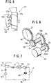
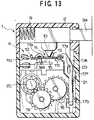
- the delay means comprises a connection rod 17 having indentations 17b formed on one side, a leading toothed wheel 18 selectively put in engagement with the indentations of the connection rod 17, an intervenient toothed wheel 19 engaged with the leading toothed wheel 18, a trailing toothed wheel 20a engaged with the intervenient toothed wheel 19, a rotary damper 20 integrally connected to the trailing toothed wheel 20a, and a curved spring plate 21 extending along the rear side of the connection rod 17.
- the connection rod 17 is so operatively connected to the seesaw-like contact lever 11 that it may rise and descend in response to counter-clockwise and clockwise inclination of the seesaw-like contact lever 11 toward the on- and off-position.
- the curved spring plate 21 applies a resilient push to the connection rod 17, thereby making it sure that the indentations 17b of the connection rod 17 are put in engagement with the leading toothed wheel 18 in response to the rise of the connection rod 17.
- connection rod 17 has a forked-and-bracketed end 17a fitted in the through hole 11c of the seesaw-like contact lever 11.
- the indentations 17b are arranged at regular intervals on one side of the connection rod 17.
- each indentation has a curved surface on one side, thereby facilitating departure of each indentation from the counter tooth of the leading toothed wheel 18 when the connection rod 17 starts descending (as indicated by arrow C) at the time of transition from the on-position to the off-position, putting the delay means in inoperative position.
- connection rod 17 is raised upward, and then, the curved spring plate 21 gives a resilient push to the connection rod 17 to put selected indentations in engagement with the leading toothed wheel 18, so that it may rotate.
- connection rod 17 has a coiled spring 22 fixed to its bottom, thereby making it sure that the connection rod 17 is raised upward.
- the toothed wheels 18 and 19 are rotatably fixed on the axles, which are fixed to one side wall of the switch casing.
- the gang of these toothed wheels 18 and 19 and the rotary damper 20 are illustrated in Fig.6.
- FIG.7 The wiring diagram of the operation-staggered dual switch comprising a short-circuit switching mechanism A and a main switching mechanism B according to the present invention is shown in Fig.7.
- an ac power supply is indicated by 23; an electric motor is indicated by 24; and a TRIAC device which is connected across the short-circuit switching mechanism A as an exterior element, is indicated by 25.
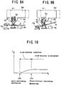
- connection rod 17 is loaded with the rotary damper 20, and accordingly the rising speed of the connection rod 17 is lowered, so that the seesaw-like contact lever 11 is tilted slowly to retard the contacting of the main contact 11b with the contact of the first power supply terminal 15.
- the short-circuit switch A therefore, turns on after the main switch B turns on.
- a slow-starter circuit using a TRIAC When a slow-starter circuit using a TRIAC is connected across the short-circuit switching mechanism A, the starting current flowing through an associated motor varies with time as shown in Fig.10.
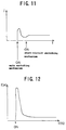
- Fig.11 shows how the starting current varies with time when the slow-starter circuit uses a resistor in place of the TRIAC.
- connection rod 17 and the seesaw-like contact lever 11 can be controlled by changing the tooth number ratio of the toothed wheels 18 to 20 and the inertia of the rotary damper 20.
- the torque to be applied to the trailing toothed wheel 20a will be lowered by increasing the tooth number Z 3 and by decreasing the tooth number Z 4 . Then, the rotary damper 20 is increasingly difficult to be rotated, and accordingly the loading is increased, and the retard in switching action is increased.
- the tooth number Z 1 of the toothed wheel 18 and the tooth number Z 2 of the relatively small toothed wheel 19a are related in the same way as described earlier, but the tooth number Z 1 of the toothed wheel 18 cannot be changed so much because the leading toothed wheel 18 must be engaged with the indentations of the connection rod 17. To change the loading as required, however, it suffices that the tooth numbers Z 3 and Z 4 are changed appropriately.
- the switching retard can be made as required simply by changing selected toothed wheels and/or by changing the rotary damper without dirtying the surrounding with oil as is the case with the oil damper.
- each indentation 17b has the effect of allowing the indentation to depart from the counter tooth smoothly in response to the descent of the connection rod 17 in the direction indicated by arrow "c" (see Fig.5).
- the seesaw-like contact lever is equipped with the quick throwing means in the short-circuit switching mechanism A, and therefore, the time length of delay cannot be significantly influenced even though the turning speed of the seesaw-like contact lever changes.
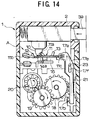
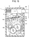
- connection rod 17 has an elongated aperture 17f made between the upper engagement portion 17a and the lower indented portion 17b of the connection rod 17.
- a rounded stud 23 projects from one side wall of the switch casing 2.
- the connection rod 17e has no spring fixed to its bottom end.
- connection rod 17e When the actuating rod 3a is released to put the switching mechanism A in the off-position, an increased moment is applied to the connection rod 17e to rotate it counter-clockwise about the rounded stud 23, thereby assuring that the connection rod 17e is departed from the toothed wheel 18 (see Fig.15) to expedite the rising of the connection rod 17e.
- connection rod 17e it is unnecessary to provide the connection rod 17e with such a spring 22 as required in the first embodiment, still assuring retard in turning on and descendent of the connection rod 17e for the off-position.
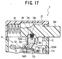
- the actuating rod 3a has a hollow retainer 3b formed on its lower side.
- the hollow retainer 3b has a spring-biased pointed pusher 10 loosely fitted therein.
- the hollow retainer 3b has two guide slits 3d made on its circumferential wall. These guide slits 3d are equal angular distances apart from each other, opening at the lower edge of the circumferential wall of the hollow retainer 3b.
- the point-ended pusher 10 has two pins 10a projecting from its outer circumference. These pins 10a are equal angular distances apart from each other, and are slidably fitted in the guide slits 3d of the hollow retainer 3b. Thus, the point-ended pusher 10 can swing about the opposite pins 10a, as seen from Fig.17.
- the hollow retainer 3b has a recess 3e made on its bottom as a seat for the spring 3c.
- the bottom end of the spring 3c is press-fitted in the recess 3e,thus permitting the spring 3c to stay stable on the bottom of the recess 3e when the actuating rod 3a is moved back and forth.
- the point-ended pusher 10 therefore, can swing stable in the hollow space of the retainer.
- a projection from the bottom of the recess may be used in place of the recessed seat.
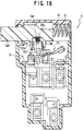
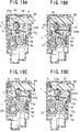
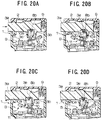
- connection rod 17 has an elongated guide aperture 17i made in the vicinity of the seesaw-like lever-and-connection rod joint at the same level as the fulcrum of the seesaw-like contact lever 11, thereby increasing the rotary moment to be applied to the connection rod 17 at the instant of departing from the toothed wheel 18 against the counter force exerted by the curved spring plate 21.
- the point-ended pusher 10 has guide studs 10a formed on its circumference, and the hollow retainer 3b has guide slits 3d made on its circumference, as is in the short-circuit switching mechanism A.
- connection rod 17g As seen from Figs.19(C) and (D), at the time of transition from the on-position to the off-position the connection rod 17g is lowered, causing the indentations of the connection rod 17g to depart from the toothed wheel 18 (in the direction indicated by arrow "d" in Fig.5). Then, the rotary torque thus produced about the stud projection 23a is increased to be strong enough to overcome the counter resilient force exerted by the curved spring plate 21, thus permitting the indentations of the connection rod 17g to depart from the toothed wheel 18 quickly.
Landscapes
- Mechanisms For Operating Contacts (AREA)
- Tumbler Switches (AREA)
Applications Claiming Priority (9)
| Application Number | Priority Date | Filing Date | Title |
|---|---|---|---|
| JP324333/97 | 1997-11-26 | ||
| JP32433397 | 1997-11-26 | ||
| JP32433397 | 1997-11-26 | ||
| JP12853498 | 1998-05-12 | ||
| JP12853498 | 1998-05-12 | ||
| JP128534/98 | 1998-05-12 | ||
| JP29533498A JP4199860B2 (ja) | 1997-11-26 | 1998-10-16 | 遅延スイッチ |
| JP295334/98 | 1998-10-16 | ||
| JP29533498 | 1998-10-16 |
Publications (2)
| Publication Number | Publication Date |
|---|---|
| EP0920037A2 true EP0920037A2 (de) | 1999-06-02 |
| EP0920037A3 EP0920037A3 (de) | 2000-03-29 |
Family
ID=27315769
Family Applications (1)
| Application Number | Title | Priority Date | Filing Date |
|---|---|---|---|
| EP98122150A Withdrawn EP0920037A3 (de) | 1997-11-26 | 1998-11-25 | Zweifachschalter mit gestaffelter Schaltfolge |
Country Status (3)
| Country | Link |
|---|---|
| US (1) | US5981885A (de) |
| EP (1) | EP0920037A3 (de) |
| JP (1) | JP4199860B2 (de) |
Cited By (4)
| Publication number | Priority date | Publication date | Assignee | Title |
|---|---|---|---|---|
| WO2000028561A1 (es) * | 1998-11-11 | 2000-05-18 | Gestion Desarrollos Electronicos, S.A. | Interruptor de red para televisor con desconexion degaussing |
| ES2146550A1 (es) * | 1998-11-11 | 2000-08-01 | Gestion Desarrollos Electronic | Interruptor de red para televisor con desconexion degaussing. |
| ES2161174A1 (es) * | 1999-11-04 | 2001-11-16 | Gestion Desarrollos Electronic | Interruptor de red para televisor con desconexion degaussing. |
| EP2626874A1 (de) * | 2012-02-10 | 2013-08-14 | Defond Components Limited | Elektrischer Schalter mit Schnappwirkungs-Mechanismus |
Families Citing this family (7)
| Publication number | Priority date | Publication date | Assignee | Title |
|---|---|---|---|---|
| US6774509B2 (en) * | 2002-01-30 | 2004-08-10 | Defond Manufacturing Limited | Electrical switch assembly |
| EP1715843A1 (de) * | 2004-01-29 | 2006-11-02 | Neuromolecular Inc. | Kombination eines nmda-rezeptor-antagonisten und eines mao-hemmers oder eines gadph-hemmers zur behandlung von erkrankungen im zusammenhang mit dem zentralen nervensystem |
| US7705260B2 (en) | 2005-04-18 | 2010-04-27 | Xinsheng Xu | Switch assembly |
| US20140131187A1 (en) * | 2012-11-10 | 2014-05-15 | Solteam Electronics Co., Ltd. | Heat-Spot Distant Type Push Switch Structure |
| CN107910217B (zh) * | 2017-11-13 | 2019-05-24 | 青岛锦绣铁科轨道设备有限公司 | 一种基于齿轮传递的电力断路器灭弧机构 |
| EP3588524B1 (de) | 2018-06-28 | 2020-08-05 | Black & Decker Inc. | Elektronisches schaltmodul mit einer integrierten schutzdiode |
| CN109637860B (zh) * | 2018-12-20 | 2020-02-07 | 郑州工程技术学院 | 一种家居用智能控制开关 |
Family Cites Families (6)
| Publication number | Priority date | Publication date | Assignee | Title |
|---|---|---|---|---|
| DE2838934C2 (de) * | 1978-09-07 | 1986-07-31 | J. & J. Marquardt, 7201 Rietheim-Weilheim | Elektrischer Schalter |
| JPS6328817A (ja) * | 1986-07-21 | 1988-02-06 | Kobe Steel Ltd | 転炉の炉体の冷却方法 |
| JPS6334176A (ja) * | 1986-07-29 | 1988-02-13 | Canon Inc | 被記録材およびそれを用いた記録方法 |
| DE4232402C5 (de) * | 1992-09-26 | 2005-10-27 | Marquardt Gmbh | Bremsschaltung für einen Elektromotor |
| US5600107A (en) * | 1995-07-27 | 1997-02-04 | Eaton Corporation | Electric switch with dynamic brake contact shared for making and breaking a power circuit |
| US5854455A (en) * | 1997-03-25 | 1998-12-29 | Ut Automotive Dearborn, Inc. | Switching device with secondary switching function |
-
1998
- 1998-10-16 JP JP29533498A patent/JP4199860B2/ja not_active Expired - Fee Related
- 1998-11-20 US US09/196,435 patent/US5981885A/en not_active Expired - Lifetime
- 1998-11-25 EP EP98122150A patent/EP0920037A3/de not_active Withdrawn
Cited By (5)
| Publication number | Priority date | Publication date | Assignee | Title |
|---|---|---|---|---|
| WO2000028561A1 (es) * | 1998-11-11 | 2000-05-18 | Gestion Desarrollos Electronicos, S.A. | Interruptor de red para televisor con desconexion degaussing |
| ES2146550A1 (es) * | 1998-11-11 | 2000-08-01 | Gestion Desarrollos Electronic | Interruptor de red para televisor con desconexion degaussing. |
| ES2161174A1 (es) * | 1999-11-04 | 2001-11-16 | Gestion Desarrollos Electronic | Interruptor de red para televisor con desconexion degaussing. |
| EP2626874A1 (de) * | 2012-02-10 | 2013-08-14 | Defond Components Limited | Elektrischer Schalter mit Schnappwirkungs-Mechanismus |
| US8604376B2 (en) | 2012-02-10 | 2013-12-10 | Defond Components Limited | Electrical switch |
Also Published As
| Publication number | Publication date |
|---|---|
| US5981885A (en) | 1999-11-09 |
| EP0920037A3 (de) | 2000-03-29 |
| JP4199860B2 (ja) | 2008-12-24 |
| JP2000036223A (ja) | 2000-02-02 |
Similar Documents
| Publication | Publication Date | Title |
|---|---|---|
| US5981885A (en) | Operation-staggered dual switch | |
| US3940585A (en) | Heavy duty push-button electrical switch | |
| US6689016B2 (en) | Method and apparatus for producing downshift signals | |
| US4286125A (en) | Electric switch with two switching parts acting at different times | |
| CN109891540B (zh) | 开关触点构造、触发开关及电动工具 | |
| US2758169A (en) | Electrical switch | |
| CA1086803A (en) | Quick lock-release mechanism for a trigger switch | |
| US3114805A (en) | Snap action electric switch | |
| JPH10184868A (ja) | シフトレバーのシフトロック装置 | |
| US6100483A (en) | Switch structure having forcedly opening-and-locking mechanism equipped therewith for emergency use | |
| US3337703A (en) | Snap switch with movable contacts on biased rocking plate | |
| US4357592A (en) | Variable resistor and switch assembly | |
| JPH05215507A (ja) | センサ | |
| CN105873787A (zh) | 用于机动车的强制降挡元件 | |
| US6028274A (en) | Fail-safe switch | |
| EP0011413A1 (de) | Schalter | |
| US4495912A (en) | Constant speed running device for automobile | |
| US2473970A (en) | Snap acting device and electric switch | |
| US2529970A (en) | Electric switch | |
| US1351161A (en) | Switch | |
| RU34035U1 (ru) | Концевой выключатель | |
| US1344925A (en) | Electric switch | |
| JPS6235230Y2 (de) | ||
| JPH0338915Y2 (de) | ||
| JPH0648717Y2 (ja) | シーソー揺動スイッチ |
Legal Events
| Date | Code | Title | Description |
|---|---|---|---|
| PUAI | Public reference made under article 153(3) epc to a published international application that has entered the european phase |
Free format text: ORIGINAL CODE: 0009012 |
|
| AK | Designated contracting states |
Kind code of ref document: A2 Designated state(s): DE GB NL |
|
| AX | Request for extension of the european patent |
Free format text: AL;LT;LV;MK;RO;SI |
|
| PUAL | Search report despatched |
Free format text: ORIGINAL CODE: 0009013 |
|
| AK | Designated contracting states |
Kind code of ref document: A3 Designated state(s): AT BE CH CY DE DK ES FI FR GB GR IE IT LI LU MC NL PT SE |
|
| AX | Request for extension of the european patent |
Free format text: AL;LT;LV;MK;RO;SI |
|
| AKX | Designation fees paid |
Free format text: DE GB NL |
|
| STAA | Information on the status of an ep patent application or granted ep patent |
Free format text: STATUS: THE APPLICATION IS DEEMED TO BE WITHDRAWN |
|
| 18D | Application deemed to be withdrawn |
Effective date: 20000930 |