EP0919946A2 - Verfahren und Gerät zum Lesen von Strichkoden - Google Patents
Verfahren und Gerät zum Lesen von Strichkoden Download PDFInfo
- Publication number
- EP0919946A2 EP0919946A2 EP98304432A EP98304432A EP0919946A2 EP 0919946 A2 EP0919946 A2 EP 0919946A2 EP 98304432 A EP98304432 A EP 98304432A EP 98304432 A EP98304432 A EP 98304432A EP 0919946 A2 EP0919946 A2 EP 0919946A2
- Authority
- EP
- European Patent Office
- Prior art keywords
- data
- bar
- cpu
- character
- demodulation
- Prior art date
- Legal status (The legal status is an assumption and is not a legal conclusion. Google has not performed a legal analysis and makes no representation as to the accuracy of the status listed.)
- Granted
Links
Images


Classifications
-
- G—PHYSICS
- G06—COMPUTING OR CALCULATING; COUNTING
- G06K—GRAPHICAL DATA READING; PRESENTATION OF DATA; RECORD CARRIERS; HANDLING RECORD CARRIERS
- G06K7/00—Methods or arrangements for sensing record carriers, e.g. for reading patterns
- G06K7/10—Methods or arrangements for sensing record carriers, e.g. for reading patterns by electromagnetic radiation, e.g. optical sensing; by corpuscular radiation
- G06K7/14—Methods or arrangements for sensing record carriers, e.g. for reading patterns by electromagnetic radiation, e.g. optical sensing; by corpuscular radiation using light without selection of wavelength, e.g. sensing reflected white light
- G06K7/1404—Methods for optical code recognition
- G06K7/146—Methods for optical code recognition the method including quality enhancement steps
- G06K7/1473—Methods for optical code recognition the method including quality enhancement steps error correction
-
- G—PHYSICS
- G06—COMPUTING OR CALCULATING; COUNTING
- G06K—GRAPHICAL DATA READING; PRESENTATION OF DATA; RECORD CARRIERS; HANDLING RECORD CARRIERS
- G06K7/00—Methods or arrangements for sensing record carriers, e.g. for reading patterns
- G06K7/10—Methods or arrangements for sensing record carriers, e.g. for reading patterns by electromagnetic radiation, e.g. optical sensing; by corpuscular radiation
- G06K7/14—Methods or arrangements for sensing record carriers, e.g. for reading patterns by electromagnetic radiation, e.g. optical sensing; by corpuscular radiation using light without selection of wavelength, e.g. sensing reflected white light
Definitions
- the present invention relates to a bar code reader and a bar code reading method for reading a bar code based on a variation of reflected light quantity obtained by scanning the bar code.
- bar codes have been widely used for facilitating the management of items for sale, as represented by POS (point-of-sale) systems in the distribution business or the like.
- POS point-of-sale
- information such as the classification and price of an item is coded into a bar code, and the bar code is printed on the item.
- scanning light from the bar code reader is irradiated onto the bar code, and the quantity of reflected light is detected. This allows the data coded into the bar code to be read, and payment for the items may be requested based on the decoded data.
- the number of sold goods is counted in real time, and may be used for inventory and stock control.
- Such bar codes may be classified into a WPC code such as a JAN code, a UPC code and an EAN code, and into a variable length second code.
- the WPC code is provided with a start guard bar (SGB) added to the leftmost edge, a center bar (CB) inserted in an intermediate part and the end guard bar (EGB) added to the rightmost edge, and is composed of a left data block including 6 or 4 data characters between the start guard bar and the center bar, and a right data block including 6 or 4 data characters between the center bar and the end guard bar.
- each character in the left data block is represented by an even parity character (a character in which the total number of modules making up the two black bars contained therein is even) or an odd parity character (a character in which the total number of modules making up the black bars contained therein is odd), and a value corresponding to the combination of the even parities and the odd parities is represented as the 13th character (flag character), whereby the 13-digit information is kept.
- a bar code reader cannot read the bar code accurately when there are creases on the bag and paper to which the bar code is printed, or when the bar code is printed out of position. Further, though the reflected light received by the bar code reader is a diffusive reflected light on the bar code surface, there is a possibility that the bar code reader may not receive enough reflected light of the light quantity corresponding to the color of each bar in the bar code due to the condition of the bar code surface.
- a bar code reader is provided with a bar width pattern detection unit for reading a bar code being stored with a plurality of data characters, each of the data characters obtained by coding predetermined pieces of data satisfying a predetermined conditional expression to detect a bar width pattern; a demodulation unit for demodulating the bar width pattern detected by the bar width pattern detection means for each of the data characters and for outputting demodulated data; and a data inference unit, when one data character in the bar code fails in being demodulated, for executing an inverse operation of the conditional expression based on demodulated data obtained by demodulating the other data characters in the bar code with the demodulation unit to infer data coded into the data character failing in being demodulated with the demodulation unit.
- a bar code reader and a bar code reading method can be provided which are capable, in a case when one character fails to be demodulated, of infering the data coded into that character based on demodulated data obtained by demodulating other characters.
- the bar width pattern detection unit reads the bar code being stored with a plurality of data characters obtained by coding predetermined pieces of data satisfying a conditional expression, and detects the read bar width pattern.
- the demodulation unit demodulates the bar width pattern detected by the bar width pattern detection unit for every data character, and outputs demodulated data.
- the data inference unit executes the inverse operation of the conditional expression based on the numerical values obtained by demodulating all other data characters in the bar code and infers data coded into the data character which failed to be demodulated by the demodulation unit. As a result, it is possible to obtain the demodulated data corresponding to the whole bar code more quickly.
- the said data character may be obtained by coding an even-odd parity distinction in the data, and the bar code may be stored with a plurality of the data characters in accordance with one combination among predetermined combinations of the even parity and the odd parity.
- the demodulation unit may demodulate the bar width pattern detected by the bar width pattern detection unit for each of the data characters and then output the data and the even-odd parity distinction, and may further comprise a parity inference unit, for use when the demodulation unit fails in demodulating one data character in the bar code, for specifying the predetermined combinations corresponding to combinations of even-odd parity distinctions obtained by demodulating the other data characters in the bar code with the demodulation unit, and for reading the even-odd parity distinction corresponding to the data character which fails to be demodulated by the demodulation unit among the specified combinations.
- a parity inference unit for use when the demodulation unit fails in demodulating one data character in the bar code, for specifying the predetermined combinations corresponding to combinations of even-odd parity distinctions obtained by demodulating the other data characters in the bar code with the demodulation unit, and for reading the even-odd parity distinction corresponding to the data character which fails to be demodulated by the demodulation
- a bar code reader embodying the first aspect of the present invention may further be provided with a comparison unit for comparing a first bar width pattern, corresponding to the data character which fails to be demodulated by the demodulation unit, and a second bar width pattern, corresponding to data inferred by the data inference unit; and a validating unit for validating the data inferred by the data inference unit only when the first bar width pattern coincides with the second bar width pattern at least partly as a result of comparison by said comparison unit.
- the comparison unit may compare bar widths of each pair of bars in the first bar width pattern and in the second bar width pattern, said each pair of bars corresponding to each other, and that the validating unit validates the data inferred by the data inference unit only when a ratio of bar widths of any one pair of bars is within a predetermined ratio range.
- the validating unit may, when a ratio of bar widths of any one pair of bars is within a first predetermined ratio range, immediately validate the data, and, when the ratio of bar widths of any one pair of bars is within a second predetermined ratio range exceeding the first predetermined ratio, restart the bar width pattern detection unit, the demodulation unit and the data inference unit, and may validate the data only when the ratio of bar widths of the pair of bars is within the second predetermined ratio after the restarting.
- a bar code reader embodying the first aspect of the present invention may further be provided with a comparison unit for comparing a first bar width pattern corresponding to the data character failing to be demodulated by the demodulation unit and a second bar width pattern corresponding to data inferred by the data inference unit and corresponding to the even-odd parity distinction inferred by the parity inference unit; and a validating unit for validating the data inferred by the data inference unit and the even-odd parity distinction inferred by the parity inference unit only when the first bar width pattern coincides with the second bar width pattern at least partly as a result of comparison by the comparison unit.
- the comparison unit may compare bar widths of each pair of bars in the first bar width pattern and in the second bar width pattern, the each pair of bars corresponding to each other, and the validating unit may validate the data inferred by the data inference unit and the even-odd parity distinction inferred by the parity inference unit when a ratio of bar widths of one pair of bars is within a predetermined ratio.
- the validating unit may, when a ratio of bar widths of any one pair of bars is within a first predetermined ratio, immediately validate the data, and, only when the ratio of bar widths of any one pair of bars is within a second predetermined ratio exceeding the first predetermined ratio, restart the bar width pattern detection unit, the demodulation unit, the data inference unit and the parity inference unit, and may validate the data and the distinction of an even parity an odd parity only when a the ratio of bar widths of one pair of bars is within the second predetermined ratio after the restart.
- a bar code reader embodying the first aspect of the present invention may further be provided with a validating unit for immediately validating the data inferred by the data inference when the demodulation unit demodulates data characters except one data character in the bar code based on a bar width pattern obtained by once scanning with the bar width pattern detection unit, and for restarting the bar width pattern detection unit, the demodulation unit and the data inference unit and for validating the data inferred by the data inference after the restarting when the demodulation unit demodulates data characters except one data character in the bar code based on a bar width pattern obtained by plural times of scanning with the bar code width detection unit.
- a bar code reader embodying the first aspect of the present invention may further be provided with a validating unit for immediately validating the data inferred by the data inference unit and the even-odd parity distinction inferred by the parity inference unit when the demodulation unit demodulates data characters except one data character in the bar code based on a bar width pattern obtained by once scanning with the bar width pattern detection unit, and for restarting the bar width pattern detection unit, the demodulation unit and the data inference unit and for validating the data inferred by the data inference unit and the even-odd parity distinction inferred by the parity inference unit after the restart when the demodulation unit demodulates data characters except one data character in the bar code based on a bar width pattern obtained by plural times of scanning with the bar width pattern detection unit.
- a method of reading a bar code with a step of reading a bar code being stored with a plurality of data characters obtained by coding a predetermined pieces of data satisfying a predetermined conditional expression to detect a bar width pattern; a step of demodulating the bar width pattern which is detected for each of the data characters and of outputting demodulated data; and a step, when one data character fails to be demodulated, of executing an inverse operation of the conditional expression(based on data obtained by demodulating the other data characters in the bar code)to infer data coded into the data character failing to be demodulated.
- a 13-digit bar code is provided with a start guard bar (SGB) consisting of a fixed pattern of bars (three bars of black, white, black, each bar consisting of 1 module) to the left, a center bar (CB) consisting of a fixed pattern of bars (five bars of white, black, white, black, white, each bar consisting of 1 module) in the middle, and an end guard bar (EGB) consisting of a fixed pattern of bars (three bars of black, white, black, each bar consisting of 1 module) to the right.
- SGB start guard bar
- CB center bar
- EGB end guard bar
- the bar code is also provided with a left data block consisting of 6 data characters (Cl through C6) between the start guard bar (SGB) and the center bar (CB), and a right data block consisting of 6 data characters (C7 through C12) between the center bar (CB) and the end guard bar (EGB).
- a left data block consisting of 6 data characters (Cl through C6) between the start guard bar (SGB) and the center bar (CB)
- a right data block consisting of 6 data characters (C7 through C12) between the center bar (CB) and the end guard bar (EGB).
- Each data character (C1 though C12), as shown in FIGs. 26 and 28, consists of a combination of two white bars and two black bars formed by appropriately assigning white or black to each of seven modules (each module having a unit length).
- the four bars in each data character are arranged in order of white bar (a), black bar (b), white bar (c), and black bar (d) from the start guard bar (SGB), and in each data character (C7 through C12) of the right data block, the four bars are arranged in order of white bar (a), black bar (b), white bar (c), and black bar (d) from the end guard bar (EGB).
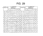
- FIG. 29 is a table showing all bar width (module number) patterns capable being each bar (a, b, c, d) of data character and numerical values corresponding to the bar width patterns.
- E- added to the numeral value indicates a data character of even parity (a character in which the sum of modules of both black bars (b, d) is even)
- O- indicates a data character of odd parity (a character in which the sum of modules of both black bars (b, d) is odd).
- T2 indicates a bar width (number of modules) obtained by summing black bar (d) and white bar (c) and T1 indicates a bar width (number of modules) obtained by summing white bar (c) and black bar (b), and both are called " ⁇ distance”.
- the right data block consists of only data characters of even parity
- the left data block consists of data characters of even parity and data characters of odd parity.
- combinations of even parity and odd parity of the 6 data characters in the left data block are limited to 10 ways as shown in FIG. 30 according to the standard of the WPC code.
- one numeral value (0 through 9), namely, a flag character, is defined for each combination.
- each combination pattern of even parity and odd parity hereinafter, called "ODD/EVEN structure" capable of being taken by the 6 data characters in the left data block differs from another combination pattern in two or more characters.
- the combination pattern of the ODD/EVEN structure in the left block is "OO-OEE" where "-" denotes the missing character.
- any combination pattern of the ODD/EVEN) structure capable becoming 6 data characters in the left data block differs from another combination pattern of the ODD/EVEN structure in two or more characters. Accordingly, when any of the data characters is omitted, the combination pattern of the ODD/EVEN structure of the remaining 5 characters differs from another combination pattern of the ODD/EVEN structure in one character at least. In the case shown in FIG.
- the numerical value inferred in this way may be used as it is; however, it is desirable to inspect the inference result in order to ensure the accuracy thereof since its numerical value is inferred on the assumption that the other 11 demodulated characters are correct. So, the inferred ODD/EVEN structure and the bar width pattern corresponding to the numerical value are read from the table shown in FIG. 29, the number of modules of each bar to be the read bar width pattern is compared with the bar width data actually detected as to the data character failing in modulation, and it is determined whether any of the ⁇ distance T1, the ⁇ distance T2, the black bar (b), and the black (d) coincide, whereby the inference result becomes accurate.
- a bar code reader embodying the present invention is provided with a bar width pattern detection unit 100 for reading a bar code (stored with a plurality of data characters obtained by coding a predetermined number of pieces of data satisfying a predetermined conditional expression)and detecting the read bar code; a demodulation unit 101 for demodulating the bar code detected by the bar code detection unit and outputting demodulated data; and an inference unit 102, when one data character in the bar code is not demodulated, for calculating back the conditional expression based on demodulated data obtained by demodulating other data characters in the bar code with the demodulation unit and inferring the data coded into the data character not demodulated by the demodulation unit.
- the bar width pattern detection unit 100 reads the bar code stored with plural data characters obtained by coding the predetermined number of pieces of data satisfying the predetermined conditional expression, and detects the read bar width pattern.
- the demodulation unit 101 demodulates every data character of the bar code detected by the bar width pattern detection unit, and outputs this demodulated data.
- the data inference unit (102) calculates back the conditional expression based on the numerical value obtained by demodulating other data characters in the bar code with the demodulation unit, and infers data coded into the data character not demodulated by the demodulation unit. As a result, demodulated data corresponding to the whole bar code can be obtained immediately.
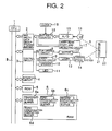
- FIG. 2 is a block diagram showing an outline configuration of a bar code reader of the embodiment according to the present invention.
- the bar code reader is provided with a CPU 1, a bar width data group storing buffer 2, a control circuit 3, an interface circuit 4, a ROM 5 and a RAM 6 connected to one another via a bus B; a bar width counter 16 and a laser beam start-end detecting circuit 17 connected to the bar width data group storing buffer 2; a clock 19 and an A/D converter 15 connected to the bar width counter 16; a light receiving element 18 connected to the A/D converter 15; a motor driving circuit 8, a laser driving circuit 9, a speaker 10 and a LED 11 respectively connected to the control circuit 3; a motor 12 connected to the motor driving circuit 8; a scanning optical system 14 driven by the motor 12; and a semiconductor laser 13 connected to the laser driving circuit 9.
- the ROM 5 is a read only memory storing the tables shown in FIGs. 29 and 30 and a bar code recognition/ demodulation process program.
- the CPU 1 executes the bar code recognition/ demodulation process program stored in the ROM 5, thereby having control over much of the bar code reader and functioning as the demodulation unit, the data inference unit, the parity inference unit, the comparison unit and the validation unit so as to demodulate the bar width data obtained by reading the bar code 21.
- the interface circuit 4 controls the status of the bus B, and controls data transmission to an external device and so on.
- the control circuit 3 controls the motor driving circuit 8, the laser driving circuit 9, the speaker 10, and the light emitting diode (LED) 11.
- This motor driving circuit 8 drives the motor 12 so as to rotate a polygon mirror(not shown)in the scanning optical system 14.
- the laser driving circuit 9 drives the semiconductor laser 13 so that a laser beam L is emitted.
- the speaker 10 produces a sound indicating the completion of bar code reading (demodulating).
- the light emitting diode 11 is an indicating element indicating information such as a price of a item 20 obtained as a result of the demodulation of the bar code.
- the laser beam L emitted from the semiconductor laser 13 is incident onto the scanning optical system 14, and is deflected by the scanning optical system 14. That is, the scanning optical system 14 deflects the laser beam L in one direction with the (not shown) polygon mirror rotated by the motor 12. At the opposite side of the polygon mirror, several mirrors are fixed. Accordingly, the laser beam L deflected by the polygon mirror is reflected again by each fixed mirror, whereby the deflection direction (scanning direction) is changed into various directions.
- laser beam scanning in plural directions is continuously performed at a high-speed in the deflection cycle by one reflective surface of the polygon mirror.
- each laser beam scanning performed in the deflection cycle by one reflective surface of the polygon mirror is called "one scanning".
- the A/D converter 15 compares the fixed threshold value with the current value (which indicates the power of the reflected light R received by the light receiving element 18), and converts the current value into a binary signal.
- the binary signal indicates "H” when the strength of the reflected light R corresponds to the reflectance ratio of a black bar in the bar code 21, and indicates "L” when the strength of the reflected R corresponds to the reflectance ratio of a a white bar in the bar code 21.
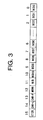
- the bar width counter 16 based on the binary signal inputted from the A/D converter 15, measures a time from the rising timing to the falling timing of the binary signal (expected to correspond to the width of the black bar in the bar code 21) and measures a time from the falling timing to the rising timing of the binary signal (expected to correspond to the width of the white bar in the bar code 21). In addition, the bar width counter 16 counts the clock number from the clock 19 in order to measure the time corresponding to these bar widths. Then, the bar width counter 16 outputs 16-bit bar width data shown in FIG. 3 every bar.
- 11-digits from the zeroth bit to the tenth bit show count values indicating bar widths
- the thirteenth bit becomes "1" when a black bar is detected in the pattern which may be the start guard bar, or when a white bar is detected in the pattern which may be the start guard bar.
- the 14th bit (CHR-L) becomes "1" when a white bar is detected in the pattern which may be the end guard bar.
- the 15th bit (C128) is an identification flag.
- the bar width counter 16 continuously outputs such bar width data every scanning of the laser beam.
- the bar width data continuously outputted every scanning is called "bar width data group”.
- the control circuit 3 the motor driving circuit 8, the motor 12, the laser driving circuit 9, the semiconductor laser 13, the scanning optical system 14, the light receiving element 18, the A/D converter 15, the bar width counter 16 and the clock 19 are equivalent to the bar width pattern detection unit of FIG. 1.
- the bar width data group outputted from the bar width counter 16 is inputted into the laser beam start-end detecting circuit 17.
- the laser beam start-end detecting circuit 17 inspects the status of the bar width data group and detects the scanning start point and the scanning end point of the laser beam in one scanning, and adds information indicating the start point and the end point to the bar width data group.
- the bar width data group (to which is added the information indicating the scanning start point and the scanning end point of the laser beam) is temporarily stored in the bar width data group storing buffer 2.
- the bar width data group storing buffer 2 sequentially stores the bar width data groups inputted from the bar width counter 16 and transfers them to the CPU 1 in order of storing one by one in response to a request from the CPU 1.
- the CPU 1 executes the bar code recognition/demodulation process program, whereby a temporary saving buffer 6a, a first demodulation completion buffer 6b, a second demodulation completion buffer 6c and a third demodulation completion buffer 6d are developed.
- the temporary saving buffer 6a while the bar code recognition/demodulation process for each bar width data group is executed, temporarily saves the data (demodulated data) obtained as a result of the process.
- the format of the demodulated data saved in the temporary saving buffer 6a is explained with reference to FIGs. 4 through 6.
- FIG. 4 shows the data format when the bar code 21 is scanned from the start guard bar as starting point (the scanning is called “continuous reading” when the bar code is read from the start guard bar to the end guard bar at a time).
- the data format in this case in sequence from the top, is provided with an area showing classification of the demodulated data (indicating the demodulated data of the 13-digit bar code in a case of "01"), an area showing a retrieval direction (showing that the start guard bar is included in a case of "01"), an area showing the character number of the demodulated data in the left data block, an area showing the character number of the demodulated data in the right data block, an area storing demodulated data in the left data block, an area storing demodulated data in the right data block, an area storing four pieces of bar width data to be a data character firstly failing in demodulation, and an area storing a character length of a data character immediately before the data character firstly failing in demodulation (at the side of
- FIG. 5 shows a data format when the bar code 21 is scanned from the end guard bar as starting point.
- the data format in this case in sequence from the top, is provided with an area showing classification of the demodulated data (indicating demodulated data of the 13-digit bar code in a case of "01"), an area showing a retrieval direction (showing that the end guard bar is included but the start guard bar is not in a case of "02"), an area showing the number of characters of the demodulated data in the left data block, an area showing the number of characters of the demodulated data in the right data block, an area storing demodulated data in the left data block, an area storing demodulated data in the right data block, an area storing four pieces of bar width data to be a data character firstly failing in demodulation, and an area storing a character length of a data character immediately before the data character firstly failing in demodulation (at the side of the end guard bar).
- FIG. 6 shows a data format when the bar code 21 is scanned over the center bar.
- the data format in this case in sequence from the top, is provided with an area showing classification of the demodulated data (indicating demodulated data of the 13-digit bar code in a case of "01"), an area showing a retrieval direction (showing that only the center bar is included in a case of "03"), an area showing the number of characters of the demodulated data in the left data block, an area showing the number of characters of demodulated data in the right data block, an area storing demodulated data in the left data block, an area storing demodulated data in the right data block, an area storing four pieces of bar width data to be a data character firstly failing in demodulation in the right data block (in the forward direction), an area storing four pieces of bar width data to be a data character firstly failing in demodulation in the left data block (in the backward direction), an area storing a character length of a data character immediately before the data character first
- the first demodulation completion buffer 6b when demodulated data shown in FIG. 4 is obtained as a result of execution of the bar code recognition/demodulation process for one bar width data group, stores the demodulated data, and is structured as shown in FIG. 7.
- the second demodulation completion buffer 6c when demodulated data shown in FIG. 5 is obtained as a result of execution of the bar code recognition/demodulation process for one bar width data group, stores the demodulated data, and is structured as shown in FIG. 8.
- the third demodulation completion buffer 6d when demodulated data shown in FIG. 6 is obtained as a result of execution of the bar code recognition/demodulation process for one bar width data group, stores the demodulated data, and is structured as shown in FIG. 9.
- the flowchart in FIG. 10, which is the main routine of the bar code recognition/demodulation process, starts by supplying a main power source to the bar code reader and by storing the bar width data group in the bar width data group storing buffer 2.
- the CPU 1 takes out the oldest bar width data group from the bar width data group storing buffer 2.
- FIG. 11 is a flowchart showing the first retrieval process subroutine executed in the S001.
- the CPU 1 after entering the subroutine, firstly executes a loop process of S101 through S103 so as to retrieve bar width data of which the CHR-L bit or the CHR-F bit is "1" among the bar width data group to be processed.
- the CPU 1 sets a bar code retrieval pointer showing a position of bar width data to be detected at the top of the bar width data group to be processed when executing the loop process at first.
- the CPU 1 checks whether the CHR-L bit or CHR-F bit in the bar width data indicated by the bar code retrieval pointer is "1" or not. The CPU 1 advances the process to S102 when the CHR-L bit and the CHR-F bit in the bar width data are "0".
- the CPU 1 executes increment of the bar code retrieval pointer so that the next bar width data is indicated.
- the CPU 1 checks whether there is an undetected bar width data or not (whether the bar code retrieval pointer exceeds the end of the bar width data group to be processed or not). The CPU 1 advances the process to S016 in the main routine in FIG. 10 when there is already no undetected bar width data group. Contrariwise, the CPU 1 returns the process to S101 when there is still an undetected bar width data group.
- the CPU 1 advances the process to the S104 when judging that the CHR-L bit or the CHR-F bit of the bar width data indicated by the bar code retrieval pointer is "1" in the S101.
- the CPU 1 checks whether the W/B bit of the bar width data indicated by the bar code retrieval pointer shows a black bar or not. The CPU 1 advances the process to the S105 when the W/B bit of the bar width data shows a black bar.
- a pseudo start guard bar a pattern like a start guard bar
- the CPU 1 advances the process to the S107 when judging in the S104 that the W/B bit in the bar width data indicated by the bar code retrieval pointer shows a white bar.
- the CPU 1 checks whether the CHR-F bit in the bar width data indicated by the bar code retrieval pointer is "1" or not. Then, the CPU 1 advances the process to the S111 when the CHR-F bit in the bar width data is "0".
- the CPU 1 executes a center bar check in the S108 when the CHR-F bit in the bar width data is "1".
- the center bar check is a check whether bar widths of five bars (white bar, black bar, white bar, black bar, white bar) detected by the point of time are regular or not.
- the CPU 1 advances the process to the S111 when the result of the center bar check is failure (NO in the S109).
- the CPU 1 advances the process to the S111 after turning a "CB check flag" to ON in the S110, when the result of the center bar check is good (YES in the S109).
- the CPU 1 checks whether the CHR-L bit in the bar width data indicated by the bar code retrieval pointer is "1". Then, the CPU 1 advances the process to the S115 when the CHR-L in the bar width data is "0".
- the CPU 1 executes an end guard bar check in the S112 when the CHR-L in the bar width data is "1".
- the end guard bar check is a check whether a white bar detected immediately before the point of time is provided an enough width as a margin or not.
- the CPU 1 advances the process to S115 when the result of the end guard bar check is failure (NO in the S113).
- the CPU 1 advances the process to the S115 after turning a "EGB check flag" ON in the S114, when the result of the end guard bar check is good (YES in the S113).
- the CPU 1 checks whether only "CB check flag” is turned ON or not.
- the CPU 1 checks whether both of "CB check flag” and "EGB check flag” are turned ON in the next S119 when judging that only the "EGB check flag” is turned ON in the S117.
- the CPU 1 takes that an operational mistake of the bar width 16 produces, and advances the process to the S102 when both check flags are OFF.
- the CPU 1 checks character lengths of the eleventh character and the twelfth character in the next S120 when both check flags are turned ON. In other words, the CPU 1, assuming that the end guard bar is detected, checks whether a bar width total of four bars adjacent to the end guard bar and a bar width total of four bars further adjacent to the four bars are in a tolerance as the character length. Then, the CPU 1 advances the process to the S102 when the character lengths of the eleventh character and the twelfth character are in the tolerance (YES in the S12-1).
- FIG. 12 is a flowchart showing the second retrieval process subroutine executed in the S002.
- the CPU 1 advances the process to the S203 when the flag decrirec is not set with "01".
- the CPU 1 executes the first bar code detection process which is a bar code retrieval process after detecting the pseudo start guard bar in the S202, when the flag decrirec is set with "01".
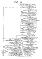
- FIGs. 13 and 14 are flowcharts showing the first bar code retrieval process subroutine executed in the S202.
- the CPU 1 checks the length of the adjacent character (the second character adjacent to the first character initially). The CPU 1 advances the process to the S306 when the length of this character is around the fixed value.
- the CPU 1 checks whether the character length check for 6 characters is completed in the S301 and the S302 by this point of time. The CPU 1 returns the process to the S302 when the character length check for 6 characters is not yet completed. On the contrary, the CPU 1 advances the process to the S308 after clearing "4-digit flag" in the S307, when the character length check for 6 characters is already completed.
- the CPU 1 in the S303 checks whether the number of characters judged as the character length is around the fixed value in the S301 and the S302 is less than three or not, when judging that the length of the adjacent character is not around the fixed value in the 5 302.
- the CPU 1 when the number of characters judged as the character length is around the fixed value is less than three takes that the reliability of the bar width data group to be processed is low, and then clears the "valid label detecting flag" in the S320, thereafter, advances the process to the S016 in the main routine shown in FIG. 10.
- the CPU 1 when the number of character judged as the character length is around the fixed value is three or more, in the S304, checks whether the number of characters judged as the character length is around the fixed value in the S301 and the S302 is four or not. The CPU 1 advances the process to the S318 when the number of characters judged as the character length is around the fixed value is not four.
- the CPU 1 when the number of characters judged as the character length is around the fixed value is 4, advances the process to the S308 after setting a "four-digit flag" in the S305.
- the CPU 1 checks again the length of the fourth character (when "four-digit flag is set) or the sixth character (when "four-digit flag” is cleared). Then, the CPU 1, when the length of the fourth character or the sixth character is around the fixed value, advances the process to the S318 after clearing the "four-digit flag" in the S310 (skipping the S310 when already cleared).
- the CPU 1 executes the center bar check in the S309 when the length of the fourth character or the sixth character is around the fixed value.
- the center bar check is a check whether five bars adjacent to the fourth character (when "four-digit flag” is set) or the sixth character (when "four-digit flag” is cleared) is coincide with a pattern predetermined as the center bar (a pattern in which each bar width is 1 module length).
- the CPU 1 advances the process to the S318 after clearing the "four-digit flag" in the S310 when the result of the center bar check is failure (NG).
- the CPU 1 sets a "center bar detection flag” in the S311 when the result of the center bar check is good (OK). That is, the flag gb-cb-f is set to "1".
- the CPU 1 checks the length of the fifth character adjacent to the center bar (when "four - digit flag is set) or the seventh character (when "four-digit flag” is cleared). The CPU 1 advances the process to the S318 when the length of the fifth character or the seventh character is around the fixed value. On the other hand, the CPU 1 advances the process to the S313 when the length of the fifth character or the seventh character is around the fixed value.
- the CPU 1 checks the length of the adjacent character (the sixth character adjacent to the fifth character, or the eighth character adjacent to the seventh character initially). The CPU 1 advances the process to the S314 when the length of this character is around the fixed value.
- the CPU 1 checks whether the "four-digit flag" is set or not. The CPU 1 advances the process to the S316 when the "four-digit flag" is cleared. Contrariwise, the CPU 1, in the S315, checks whether the character length check for 4 characters is completed in the S312 and the S313 by this point of time, when the "four-digit flag" is set. Then, the CPU 1 advances the process to the S316 when the character length check for 4 characters is not yet completed. Alternately, the CPU 1 advances the process to the S317 when the character length check of 4 characters is already completed.
- the CPU 1 checks whether the character length check for 6 characters is completed in the S312 and the S313 by this point of time. The CPU 1 returns the process to the S313 when the character length check for 6 characters is not yet completed. On the contrary, the CPU 1 advances the process to the S317 when the character length check for 6 characters is already completed.
- the CPU 1 checks again the length of the eighth character (when the "four-digit flag” is set) or the twelfth character (when "four-digit flag” is cleared). The CPU 1 advances the process to the S318 when the length of the eighth character or the twelfth character is not around the fixed value, and advances the process to the S321 when the length of the eighth character or the twelfth character is around the fixed value.
- the CPU 1 executes a valid character number detection process.
- the CPU 1 sets to a counter jun-cnt with the number of characters to be the left block judged as the character length is around the fixed value in the S301, the S302, and the S308, and sets to a counter gku-cnt with the number of characters to be the right block judged as the character length is around the fixed value in the S312, the S313, and the S317.
- the CPU 1 advances the process to the S319.
- the CPU 1 checks whether the "four-digit flag" is cleared or not. The CPU 1 advances the process to the S325 when the "four-digit flag" is cleared, and advances the process to the S322 when the "four-digit flag" is set.
- the CPU 1 executes a simple end character length check.
- the CPU 1 checks whether three bars adjacent to the eighth character are coincide with a pattern predetermined as the end guard bar (a pattern in which each bar width is 1 module length) and a white bar adjacent to the three bars is provided with a bar width longer than a length determined as an end margin. Then, the CPU 1 advances the process to the S324 when the result of the simple end character length check is failure (NG).
- the CPU I sets the "end guard bar detection flag" in the S323 when the result of the simple end character length check is good (OK). That is, the flag gb-cb-f is rewritten by "2".
- the CPU 1 advances the process to the S324 after completing the S323.
- the CPU 1 executes the above-described valid character number detection process.
- the CPU 1 sets to the counter jun-cnt with the number of characters to be the left data block judged as the character length is around the fixed value in the S301, the S302, and the S308, and sets to the counter gku-cnt with the number of characters to be the right data block judged as the character length is around the fixed value in the S312, the S313, and the S317.
- the CPU 1 advances the process to the S319.
- the CPU 1 executes the end margin check.
- the CPU 1 checks whether three bars adjacent to the twelfth character are coincide with a pattern predetermined as the end guard bar (a pattern in which each bar width is 1 module length), and a white bar adjacent to these three bars is provided with a bar width longer than a length determined as the end margin.
- the CPU 1 advances the process to the S327 when the result of the end margin check is failure (NG).
- the CPU 1 sets the "end guard bar detection flag" in the S326 when the result of the end margin check is good (OK). That is, the flag gb-cb-f is rewritten by "2".
- the CPU 1 advances the process to the S327 after completing this S326.
- the CPU 1 executes the above-described valid character number detection process.
- the CPU 1 sets to the counter jun-cnt with the number of characters to be the left data block judged as the character length is around the fixed value in the S301, the S302, and the S308, and sets to the counter gku-cnt with the number of characters to be the right data block judged as the character length is around the fixed value in the S312, the S313, and the S317.
- the CPU 1 advances the process to the S319.
- the CPU 1 sets the "valid label detection flag". Thereafter, the CPU 1 terminates the first bar code detection process routine, and returns the process to the second retrieval process routine shown in FIG. 12. In the second retrieval process routine, the CPU 1 advances the process to the S203 after completing the S202.
- the CPU 1 checks whether the flag decrirec is set with "03" or not.
- the CPU 1 advances the process to the S205 when the flag decrirec is not set with "03".
- the CPU 1 executes the second bar code detection process which is a bar code retrieval process after detecting the pseudo center bar detection in the S204 when the flag decrirec is set to "03".
- FIG. 15 is a flowchart showing the second bar code retrieval process subroutine executed in the S204.
- the CPU 1 when the length of the fifth character or the seventh character is not around the fixed value, takes that reliability of the bar width data group to be processed is low, and clears the "valid label detection flag" in the S426, thereafter, advances the process to the S016 in the main routine shown in FIG. 5.
- the CPU 1 advances the process to the S402 when the length of the fifth character or the seventh character is around the fixed value.
- the CPU 1 checks the length of the character adjacent to the pseudo center guard bar in the backward direction (the fourth character in a case of the 8-digit bar code, the sixth character in a case of the 13-digit bar code). The CPU 1 advances the process to the S404 when the length of the fourth character or the sixth character is around the fixed value. On the other hand, the CPU 1 sets a "backward direction no-data flag" in the S403, and then advances the process to the S404 when the length of the fourth character or the sixth character is not around the fixed value.
- the CPU 1 checks whether the "backward direction no-data flag" is set or not. The CPU 1 advances the process to the S408 when the "backward direction no-data flag" is set. On the contrary, the CPU 1 advances the process to the S405 when the "backward direction no-data flag" is not set.
- the CPU 1 checks the length of the character adjacent to the fourth character or the sixth character in the backward direction (initially, the third character adjacent to the fourth character, or the fifth character adjacent to the sixth character). Then, the CPU 1 advances the process to the S406 when the length of this character is around the fixed value.
- the CPU 1 counts the number of characters (characters continuing in the backward direction) judged as the character length is around the fixed value in the S402 and the S405 by this point of time.
- the CPU 1 checks whether or not the character length check for 6 characters is completed in the S402 and the S405 by this point of time.
- the CPU 1 returns the process to the S405 when the character length check for 6 characters is not yet completed.
- the CPU 1 advances the process to the S408 when the character length check for 6 characters is already completed.
- the CPU 1 advances the process to the S408 when judging that the length of the adjacent character is not around the fixed value in the S405.
- the CPU 1 checks the length of the character adjacent to the fifth character or the seventh character in the forward direction (initially, the sixth character adjacent to the fifth character, or the eighth character adjacent to the seventh character). The CPU 1 advances the process to the S409 when the length of this character is around the fixed value.
- the CPU 1 counts the number of the characters (characters continuing in the forward direction) judged as the character length is around the fixed value in the S401 and the S408 by this point of time.
- the CPU 1 checks whether or not the character length check for 6 characters is completed in the S401 and the S408 by this point of time. The CPU 1 returns the process to the S408 when the character length check for 6 characters is not yet completed. On the contrary, the CPU 1 advances the process to the S411 when the character length check for 6 characters is already completed.
- the CPU 1 advances the process to the S411 when judging that the length of the adjacent character is not around the fixed value in the S408.
- the CPU 1 checks whether the "backward direction no-data flag" is set or not. The CPU 1 advances the process to the S412 when the "backward direction no-data flag" is not set, and advances the process to the S418 when the "backward direction no-data flag" is set.
- the CPU 1 checks whether or not the number of valid characters in the backward direction counted in the S406 is "1" or more and the number of valid characters in the forward direction counted in the S409 is "3" or more, or, whether or not the number of valid characters in the backward direction counted in the S406 is "3" or more and the number of valid characters in the forward direction counted in the S409 is "1" or more.
- the CPU 1 when the number of valid characters in any direction is less than "3" and the number of valid characters in one direction is "0", takes that reliability of the bar width data group to be processed is low, and then clears the "effective label detection flag" in the S426, thereafter, advances the process to the S016 in the main routine shown in FIG. 10. Alternately, the CPU 1 advances the process to the S413 when the number of effective characters in one direction is "3" or more and the number of effective characters in another direction is "1" or more.
- the CPU 1 checks whether the number of the valid characters in the backward direction counted in the S406 is "4 (in a case of eight-digit bar code)" or "6 (in a case of 13-digit bar code)". The CPU 1 advances the process to the S416 when the number of valid characters in the backward direction is not "4" or "6", and advances the process to the S414 when the number of valid characters in the backward direction is "4" or "6".
- the CPU 1 checks the length of the first character again.
- the CPU 1 advances the process to the S416 when the length of the first character is not around the fixed value, and advances the process to the S415 when the length of the first character is around the fixed value.
- the CPU 1 checks whether or not the number of valid characters in the forward direction counted in the S409 is "4 (in a case of 8-digit bar code)" or "6 (in a case of 13-digit bar code)".
- the CPU 1 advances the process to the S419 when the number of valid characters in the forward direction is "4" or "6”, and advances the process to the S416 when the number of valid characters in the forward direction is not"4" or "6".
- the CPU 1 executes the valid character number detection process.
- the CPU 1 sets to the counter gku-cnt with the number of effective characters in the forward direction counted in the S409, and to the counter jun-cnt with the number of valid characters in the backward direction counted in the S406.
- the CPU 1 sets the "valid label detection flag" in the S317, and then terminates the second bar code detection process routine so as to return to the second retrieval process routine shown in FIG. 12.
- the CPU 1 checks whether the number of effective characters number in the forward direction counted in the S409 is "4 (in a case of eight-digit bar code)" or "6 (in a case of 13-digit bar code)".
- the CPU 1 when the number of effective character numbers in the forward direction is not "4" or "6", clears the "valid label detection flag" in the S426, and then advances the process to the S016 in the main routine shown in FIG. 10. Alternately, the CPU 1 advances the process to the S419 when the number of valid characters in the forward direction is "4" or "6".
- the CPU 1 checks the length of the eighth character (when it is judged that the number of characters in the forward direction is "4" in the S418) or the twelfth character (when it is judged that the number of characters in the forward direction is "6" in the S418) again.
- the CPU 1 advances the process to the S425 when the length of the eighth character or the twelfth character is not around the fixed value.
- the CPU 1 advances the process to the S420 when the length of the eighth character or the twelfth character is around the fixed value.
- the CPU 1 executes the end margin check.
- the CPU 1 checks whether three bars adjacent to the eighth character (when it is judged that the number of effective characters in the forward direction is "4" in the S418) or the twelfth character (when it is judged that the number of effective characters in the forward direction is "6" in the S418) are coincide with a pattern predetermined as the end guard bar (the pattern in which each bar width is 1 module length), and a white bar adjacent to the three bars is provided with a bar width longer than the length defined as the end guard bar.
- the CPU 1 advances the process to the S425 when the result of the end margin check is failure (NG). Alternately, the CPU 1 advances the process to the S421 when the result of the end margin check is good (OK).
- the CPU 1 checks whether the "backward direction no-data flag" is set or not.
- the CPU 1 when the "backward direction no-data flag” is set, clears the "valid label detection flag” in the S426, and then advances the process to the S016 in the main routine shown in FIG. 10. Alternately, the CPU 1 advances the process to the S424 when the "backward direction no-data flag" is not set.
- the CPU 1 checks whether the number of effective characters counted in the S409 is "4" or not. The CPU 1 advances the process to the S423 when the number of effective characters is not "4", and advances the process to S423 after setting "four-digit flag" in the S422 when the number of effective characters is "4".
- the CPU 1 sets the "end guard bar detection flag". That is, the CPU 1 sets "1" to the flag gb-cb-f. Thereafter, the CPU 1 advances the process to the S424.
- the CPU 1 executes the valid character number detection process.
- the CPU 1 sets to the counter gku-cnt with the number of valid characters in the forward direction counted in the S409, and sets to the counter jun-cnt with the number of valid characters in the backward direction counted in the S406.
- the CPU 1 sets the "valid label detection flag" in the S317, and then terminates the second bar code detection process routine so as to return to the second retrieval process routine shown in FIG. 12.
- the CPU 1 advances the process to the S205 when returning to the second retrieval process routine.
- the CPU 1 checks whether the flag decrirec is set for "02".
- the CPU 1 when the flag decrirec is not set for "02", takes that an operational mistake produces, and advances the process to the S016 in the main routine shown in FIG. 10.
- the CPU 1 when the flag decrirec is set for "02", executes the third bar code detection process which is a bar code retrieval process after detecting the pseudo end guard bar in the S206.
- FIG. 16 is a flowchart showing the third bar code retrieval process subroutine executed in the S206.
- the CPU 1 executes the end character length check. In other words, the CPU 1 checks the total of bar widths of four bars adjacent to the pseudo end guard bar. The CPU 1, when the length of the end character is not around the fixed value, takes that reliability of the bar width data group to be processed is low, and then clears the "valid label detection flag" in the S507, thereafter, advances the process to the S016 in the main routine shown in FIG. 10. Alternately, the CPU 1, when the length of the end character is around the fixed value, advances the process to the S502.
- the CPU 1 checks the lengths of the eleventh character adjacent to the end character and the tenth character.
- the CPU 1 when the length of the eleventh character or the tenth character is not around the fixed value, takes that reliability of bar width data group to be processed is low, and then clears the "effective label detection flag" in the S507, thereafter, advances the process to the S016 in the main routine shown in FIG. 10. Alternately, the CPU 1 advances the process to the S504 when both lengths of the eleventh character and the tenth character are around the fixed value.
- the CPU 1 checks the length of the adjacent character (initially, the ninth character adjacent to the tenth character). The CPU 1 advances the process to the S508 when the length of this character is not around the fixed value, and advances the process to the S505 when the length of this character is around the fixed value.
- the CPU 1 checks whether the character length check for 6 characters is completed in the S501 through the S504 by this point of time. The CPU 1 returns the process to the S504 when the character length check for 6 characters is not yet completed. On the contrary, the CPU 1 advances the process to the S506, when the character length check for 6 characters is already completed.
- the center bar check is a check whether five bars adjacent to the seventh character are coincide with a pattern determined as the center bar (a pattern in which each bar width is 1 module length).
- the CPU 1 when the result of the center bar check is good (OK), takes as an impossible status, and then clears the "valid label detection flag", thereafter, advances the process to the S016 in the main routine shown in FIG. 10. On the contrary, the CPU 1 advances the process to the S508 when the result of the center bar check is failure (NG).
- the CPU 1 executes the valid character number detection process. In other words, the CPU 1 sets to the counter jun-cnt with the number of characters judged as the character length is around the fixed value in the S501 through the S504. After completing this valid character number detection process, the CPU 1 terminates the third bar code detection process subroutine after setting the "valid label detection flag" in the S509, and then returns to the second retrieval process routine shown in FIG. 12.
- the CPU 1 terminates the second retrieval process routine after the S206, and returns the process to the main routine shown in FIG. 10.
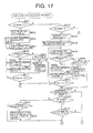
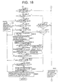
- FIGs. 17 through 19 are flowcharts showing the bar code demodulation subroutine executed in the S003.
- the CPU 1 checks whether the flag decdirec set in the S106, the S116, the S118 or the S122 is "1" or not.
- the CPU 1 sets the value of the counter jun-cnt for the variable loop-cnt in the S602 when the flag decdirec is "1" (when the pseudo start guard bar is detected for the first time).
- the CPU 1 sets the demodulation pointer at the top bar (white bar (a)) position of the first character in the bar width data group to be processed.
- the CPU 1 executes the loop process between the S604 through the S610 in order to sequentially demodulate data characters (characters judged as the length is around the fixed value) in the left data block.
- the CPU 1 executes the demodulation process for the character indicated by the demodulation pointer.
- the CPU 1 based on the bar width total ( ⁇ distance T1) of the third bar (white bar (a)) and the fourth bar (black bar (d)) counted from the white bar (a) at the position indicated by the demodulation pointer and the bar width total ( ⁇ distance T2) of the second bar (black bar (b)) and the third bar (white bar (c)) counted from the white bar (a) at the position indicated by the demodulation pointer, retrieves the list shown in FIG. 29, and reads the corresponding demodulated data (combination of the ODD/EVEN structure and the numerical value).
- the CPU 1 based on the number of modules of the rightmost black bar, further retrieves the list shown in FIG. 29, and specifies the corresponding demodulated data.
- the CPU 1 stores the demodulated data read and specified in this way into the specific position in the temporary saving buffer 6a (refer to FIG. 4).
- the CPU 1 checks whether the demodulation process in the S604 is successful or not. The CPU 1 advances the process to the S606 when the demodulation process is successful, and advances the process to the S607 when the demodulation process is unsuccessful.
- the CPU 1 checks whether or not the failure of the demodulation process is the first time after entering the bar code demodulation process.
- the CPU 1 when the demodulation process fails once, advances the process to the S606 after saving the bar width data of four bars to be the character failing in demodulation in the S608. On the contrary, the CPU 1 advances the process to the S611 in order to stop the demodulation process for the left data block, when the demodulation process fails twice or more times.
- the CPU 1 executes one decrement for the variable loop-cnt.
- the CPU 1 advances the demodulation pointer by four pieces of bar width data. That is, the CPU 1 sets the demodulation pointer to the top bar (white bar (a)) of the data character adjacent in the forward direction.
- the CPU 1 checks whether the variable loop-cnt is "0" or not. The CPU 1 returns the process to the S604 when the variable loop-cnt does not yet reach "0". Alternately, the CPU 1 advances the process to the S611 when the variable loop-cnt reaches "0" as a result of repeating the loop process of the S604 through the S610.
- the CPU 1 checks whether the number of the data characters judged as the demodulation process is successful in the S605 is three or more.
- the CPU 1 when the number of the data characters successful in demodulation is less than three, advances the process to the S016 shown in FIG. 10 after increment of the bar code retrieval pointer in the S632. Alternately, the CPU 1 advances the process to the S612 when the number of the data characters successful in demodulation is three or more.
- the CPU 1 checks whether "the four-digit flag” is set or not.
- the CPU 1 when the "four-digit flag” is set, in the S630, checks whether the number of the data characters judged as the demodulation process is successful in the S605 is 4 or not.
- the CPU 1 when the number of the data characters successful in demodulation is not four, advances the process to the S016 shown in FIG. 10 after increment of the bar code retrieval pointer in the S632. Alternately, the CPU 1, when the number of the data characters successful in demodulation is 4, checks whether the flag gb-cb-f is set with "2" in the S631.
- the CPU 1 advances the process to S616 when the flag gb-cb-f is set with "2", and advances the process to the S628 when the flag gb-cb-f is not set with "2".
- the CPU when judging that the "four-digit flag" is not set in the S612, in the S613, checks whether the number of the data characters judged as the demodulation process is successful in the S605 is 6 or not.
- the CPU 1 when the number of the data characters successful in demodulation is not 6, stores into the position of the temporary saving buffer 6a (refer to FIG. 4) with the bar width data of four bars saved in the S608 (the bar width data of four bars to be the data character failing in demodulation) and with the length of the data character immediately before the data character failing in demodulation.
- the CPU 1 advances the process to the S629. Alternately, the CPU 1 advances the process to the S614 when judging that the number of data characters successful in demodulation is 6.
- the CPU 1 checks whether the flag gb-cb-f is set with "0" or not. The CPU 1 advances the process to the S628 when the flag gb-cb-f is setwith "0", and advances the process to the S615 when the flag gb-cb-f is not set with "0".
- the CPU 1 checks whether the value of the counter gku-cnt is "0" or not.
- the CPU 1 when the value of the counter gku-cnt is "0”, takes that there is no data character to be the right data block and advances the process to the S628, and, when the value of the counter gku-cnt is not "0", takes that there is a data character to be the right data block and advances the process to the S616.
- the CPU 1 sets the value of the counter gku-cnt for the variable loop-cnt.
- the CPU 1 sets the demodulation pointer at the position of the top bar (white bar (a)) of the fifth character (when the "four-digit flag is set) or the seventh character (when the "four-digit flag” is not set) in the bar width data group to be processed.
- the CPU 1 execute the loop process of the S618 through the S624 in order to sequentially demodulate the data character to be the right data block (data character judged as the length is around the fixed value).
- the CPU 1 executes the demodulation process for the character indicated by the demodulation pointer.
- the CPU 1 stores the demodulated data obtained by this demodulation process into the corresponding position in the temporary saving buffer 6a (refer to FIG. 4).
- the CPU 1 checks whether the demodulation process in the S618 is successful or not. The CPU 1 advances the process to the S620 when the demodulation process is successful, and advances the process to the S621 when the demodulation process is unsuccessful.
- the CPU 1 checks whether the failure of the demodulation process is the first time or not after entering this bar code demodulation process.
- the CPU 1 when demodulation is unsuccessful once, advances the process to the S620 after saving the bar width data of four bars to be the data character failing in the demodulation process in the S622.
- the CPU 1 when demodulation is unsuccessful twice or more times, advances the process to the S625 in order to stop the demodulation process of the right data block.
- the CPU 1 executes one decrement for the variable loop-cnt.
- the CPU 1 advances the demodulation pointer by four pieces of bar width data. That is, the CPU 1 sets the demodulation pointer at the top bar of the data character adjacent in the forward direction (white bar (a)).
- the CPU 1 checks whether the variable loop-cnt is "0" or not. The CPU 1 returns the process to the S618 when the variable loop-cnt does not yet reach "0". Alternately, the CPU 1 advances the process to the S625, when the variable loop-cnt reaches "0" as a result of repeating the loop process of the S618 through the S624.
- the CPU 1 checks whether the "four-digit flag" is set or not. The CPU 1 advances the process to the S628 when the "four-digit flag” is set. On the contrary, the CPU 1 advances the process to the S626 when the "four-digit flag" is not set.
- the CPU 1 checks whether the number of the data characters judged as the demodulation process is successful in the S619 is 6 or not.
- the CPU 1 advances the process to the S628 when the number of the data character successful in demodulation is 6.
- the CPU 1 when the number of the data characters successful in demodulation is not six, stores into the corresponding position in the temporary saving buffer 6a (refer to FIG. 4) with the bar width data of four bars saved in the S622 (the bar width data of four bars to be the data character failing in demodulation) and with the length of the data character immediately before the data character failing in demodulation.
- the CPU 1 advances the process to the S628.
- the CPU 1 copies into the first demodulation completion buffer 6b (refer to FIG. 7) with the data in the temporary saving buffer 6a including the demodulated data stored in the S604 and the S618 and the bar width data of four bars stored in the S629 and the S627.
- the CPU 1 terminates the bar code demodulation process routine, and returns the process to the main routine shown in FIG. 10.
- the CPU 1 checks whether the flag decdirec set in the S106, the S116, the S118 or the S122 is "2" or not in the S633 when judging that the flag decdirec is not "1" in the S601.
- the CPU 1 sets the value of the counter jun-cnt into the variable loop-cnt in the S634 when the flag decdirec is "2" (when the end guard bar is detected at the first time).
- the CPU 1 sets the demodulation pointer at the position of the top bar (white bar (a)) of the end character in the bar width data to be processed.
- the CPU 1 executes the loop process of the S636 through the S642 in order to demodulate the data character to be the right data block (character assumed that the length is around the fixed value) sequentially in the backward direction.
- the CPU 1 executes the demodulation process for the character indicated by the demodulation pointer.
- the CPU 1 stores the demodulated data obtained by this demodulation process into the corresponding position in the temporary saving buffer 6a (refer to FIG. 5).
- the CPU 1 checks whether the demodulation process in the S636 is successful or not. The CPU 1 advances the process to the S638 when the demodulation process is successful, and advances the process to the S639 when the demodulation process is unsuccessful.
- the CPU 1 checks whether this is the first failure of the demodulation process after entering this bar code demodulation process.
- the CPU 1 when this is the first demodulation failure, advances the process to the S638 after saving the bar width data of four bars to be the data character failing in the demodulation process in the S640.
- the CPU 1 when demodulation is unsuccessful twice or more times, advances the process to the S643 in order to stop the demodulation process for the right data block.
- the CPU 1 executes one decrement for the variable loop-cnt.
- the CPU 1 turns back the demodulation pointer by four pieces of bar width data. That is, the CPU 1 sets the demodulation pointer at the top bar (white bar (a)) of the data character adjacent in the backward direction.
- the CPU 1 checks whether the variable loop-cnt is "0" or not. The CPU 1 returns the process to the S636 when the variable loop-cnt does not yet reach "0". On the contrary, the CPU 1 advances the process to the S643 when the variable loop-cnt reaches "0" as a result of repeating the loop process of the S636 through the S642.
- the CPU 1 checks whether the number of the data character judged as the demodulation process is successful in the S636 is three or more.
- the CPU 1 when the number of the data character successful in demodulation is less than three, advances the process to the S016 shown in FIG. 10 after increment of the bar code retrieval pointer in the S632. On the contrary, the CPU 1 advances the process to the S644 when the number of the data character successful in demodulation is three or more.
- the CPU 1 checks whether the "four-digit flag" is set or not.
- the CPU 1 when the "four-digit flag" is set, checks whether the number of the data characters judged as the demodulation process is successful in the S637 is 4 or not in the S645.
- the CPU 1 when the number of the data characters successful in demodulation is not 4, advances the process to the S016 shown in FIG. 10 after increment of the bar code retrieval pointer in the S632. On the contrary, the CPU 1 advances the process to the S628 when the number of the data characters successful in demodulation is four.
- the CPU 1 when judging that the "four-digit flag" is not set in the S644, checks whether the number of the data characters judged as the demodulation process is successful in the S637 is 6 or not in the S646. The CPU 1 advances the process to the S628 when the number of the data character successful in demodulation is 6, and advances the process to the S647 when the number of data characters successful in demodulation is not 6.
- the CPU 1 stores into the corresponding position in the temporary saving buffer 6a (refer to FIG. 5) with the bar width data of four bars saved in the S640 (bar width data of four bars constituting the data character failing in demodulation) and with the length of the data character immediately before the data character failing in demodulation. After the S647, the CPU 1 advances the process to the S628.
- the CPU 1 copies into the second demodulation completion buffer 6c (refer to FIG. 8) with the data in the temporary saving buffer 6a containing the demodulated data stored in the S636 and the bar width data of four bars stored in the S640. After the S628, the CPU 1 terminates the bar code demodulation process routine, and returns the process to the main routine shown in FIG. 10.
- the CPU 1 sets the value of the counter jun-cnt for the variable loop-cnt in the S648 when judging that the flag decdirec is not "2" in the S633.
- the CPU 1 sets the demodulation pointer at the position of the top bar (white bar (a)) of the fourth character (when the "four-digit flag is set) or the sixth character (when the "four-digit flag” is not set) in the bar width data group to be processed.
- the CPU 1 executes the loop process of the S650 through the S656 in order to demodulate data characters to be the left data block (characters assumed that the length is around the fixed value) sequentially in the backward direction.
- the CPU 1 executes the demodulation process for the character indicated by the demodulation pointer.
- the CPU 1 stores the demodulated data obtained by this demodulation process into the corresponding position of the temporary saving buffer 6a (refer to FIG. 6).
- the CPU 1 checks whether the demodulation process in the S650 is successful or not. The CPU 1 advances the process to the S652 when the demodulation process is successful, and advances to the S653 when the demodulation process fails.
- the CPU 1 checks whether this is the first failure of the demodulation process after entering the loop process of the S650 through the S656.
- the CPU 1 when this is the first failure, advances the process to the S652 after saving the bar width data of four bars constituting the data character failing in the demodulation process in the S654.
- the CPU 1 when demodulation is unsuccessful twice or more times, advances the process to the S657 in order to stop the demodulation process for the left data block.
- the CPU 1 executes one decrement for the variable loop-cnt.
- the CPU 1 returns the demodulation pointer by four pieces of bar width data. That is, the CPU 1 sets the demodulation pointer at the top bar (white bar (a)) of the data character adjacent in the backward direction .
- the CPU 1 checks whether the variable loop-cnt is "0" or not. The CPU 1 returns the process to the S650 when the variable loop-cnt does not yet reach "0". On the contrary, the CPU 1 advances the process to the S657 when the variable loop-cnt reaches "0" as a result of repeating the loop process of the S650 through the S656.
- the CPU 1 sets the demodulation pointer at the position of the top bar (white bar (a)) of the fifth character (when the "four-digit flag is set) or the seventh character (when the "four-digit flag” is not set) in the bar width data group to be processed.
- the CPU 1 sets the value of the counter gku-cnt for the variable loop-cnt.
- the CPU 1 executes the loop process of the S659 through the S665 in order to demodulate data characters to be the right data block (characters assumed that the length is around the fixed value) sequentially in the forward direction.
- the CPU 1 executes the demodulation process for the character indicated by the demodulation pointer.
- the CPU 1 stores the demodulation data provided by this demodulation process into the corresponding position of the temporary saving buffer 6a (refer to FIG. 6).
- the CPU 1 checks whether the demodulation process in the S659 is successful or not. The CPU 1 advances the process to the S661 when the demodulation process is successful, and advances the process to the S662 when the demodulation process is unsuccessful.
- the CPU 1 checks whether this is the first failure of the demodulation process after entering the loop process of the S659 through the S665.
- the CPU 1 when this is the first failure, advances the process to the S661 after saving the bar width data of four bars constituting the data character failing in the demodulation process in the S663.
- the CPU 1 when demodulation is unsuccessful twice or more times, advances the process to the S666 in order to stop the demodulation process for the right data block.
- the CPU 1 executes one decrement for the variable loop-cnt.
- the CPU 1 advances the demodulation pointer by four pieces of bar width data. That is, the CPU 1 sets the demodulation pointer to the top bar (white bar (a)) of data character adjacent in the forward direction.
- the CPU 1 checks whether the variable loop-cnt is "0" or not. The CPU 1 returns the process to the S659 when the variable loop-cnt does not yet reach "0". On the contrary, the CPU 1 advances the process to the S666 when the variable loop-cnt reaches "0" as a result of repeating the loop process of the S659 through the S665.
- the CPU checks whether the number of demodulated data successful in demodulation in the S650 in the left data block is one or more and the number of demodulated data successful in demodulation in the S659 in the right data block is three or more, or whether the number of demodulated data successful in demodulation in the S650 in the left data block is three or more and the number of demodulated data successful in demodulation in the S659 in the right data block is one or more.
- the CPU 1 advances the process to the S016 shown in FIG. 10 after increment of the bar code retrieval pointer in the S632 when the number of the demodulation data in any block are less than three, and when the number of the demodulation data in one block is 0.
- the CPU 1 advances the process to the S667 when the number of demodulated data in one block is three or more and the number of demodulated data in another block is one or more.
- the CPU 1 checks whether the number of demodulated data successful in demodulating in the S659 in the left data block is 6 or not.
- the CPU 1 advances the process to the S669 when the number of demodulated data in the left data block is six, and the advances the process to the S668 when the number of demodulated data in left data block is not 6.
- the CPU 1 stores into the corresponding position of the temporary saving buffer 6a (refer to FIG. 6) with the bar width data of four bars saved in the S654 (bar width data of four bars constituting the data character failing in demodulation) and with the length of the data character immediately before the data character failing in demodulation.
- the CPU 1 advances the process to the S669.
- the CPU 1 stores into the corresponding position in the temporary saving buffer 6a (refer to FIG. 6) with the bar width data of four bars saved in the S663 (bar width data of four bars constituting the data character failing in demodulation) and with the length of the data character immediately before the data character failing in demodulation. After the S669, the CPU 1 advances the process to the S628.
- the CPU 1 copies into the third demodulation completion buffer 6d (refer to FIG. 9) with the data in the temporary saving buffer 6a containing the demodulated data stored in the S650 and the S659 and the bar width data stored in the S668 and the S669.
- the CPU 1 terminates the bar code demodulation process routine, and returns the process to the main routine shown in FIG. 10.
- the CPU 1 checks whether the bar width data group which is the process object for the bar code demodulation process in the S003 is obtained by the continuous reading or not. This check is executed based on whether the flag gb-cb-f is set with "2" in the S323 or the S326.
- the CPU 1 advances the process to the S008 when the demodulated data is not obtained by the continuous reading, namely, when the flag gb-cb-f is set with "0" or "1".
- the CPU 1 advances the process to the S005 when by the continuous reading, namely, when the flag gb-cb-f is set with "2".
- the CPU 1 checks whether all data characters contained in the bar width data group are completely demodulated by the bar code demodulation process in the S003. The CPU 1 advances the process to the S008 when all data characters are completely demodulated. On the contrary, the CPU 1 advances the process to the S006 when all data characters are not completely demodulated.
- the CPU 1 checks whether only 1 character fails in demodulation during the bar code demodulation process in the S003. The CPU 1 advances the process to the S008 when 2 or more characters fails in demodulation. On the contrary, the CPU 1, when only 1 character fails in demodulation, executes the 1-character inference process (equivalent to the data inference unit and the parity inference unit) in order to infer demodulated data corresponding to the character failing in demodulation in the S007.
- FIG. 20 is a flowchart showing the 1-character inference process subroutine executed in the S007.
- the CPU 1 checks whether the "four-digit flag" is set or not. When the "four-digit flag" is set, it is impossible to infer characters, therefore, the CPU 1 terminates the 1-character inference process subroutine promptly, and then returns the process to the main routine shown in FIG. 10. On the contrary, the CPU 1 advances the process to the S702 when the "four-digit flag" is not set.
- the CPU 1 checks whether the character failing in demodulation during the bar code demodulation process in the S003 is in the left data block or not.
- the CPU 1 advances the process to the S705 since it is unnecessary to infer the ODD/EVEN structure when the character failing in demodulation is in the right data block.
- the CPU 1 advances the process to the S703 when the character failing in demodulation is in the left data block.
- the CPU 1 infers the ODD/EVEN structure of 1-character failing in demodulation based on the 5-characters in the left data block successful in demodulation by using the list shown in FIG. 30 as above described (equivalent to the parity inference unit).
- the CPU 1 saves the ODD/EVEN structure inferred in the S703. After the S704, the CPU 1 advances the process to the S705.
- the CPU 1 calculates a corresponding flag character based on the ODD/EVEN structure of 6-characters to be the left data block (including the ODD/EVEN structure saved in the S704) by using the list shown in FIG.30.
- the CPU 1 based on the numerical values of 11-characters successful in demodulation and the numerical value of the flag character calculated in the S705, calculates back the modulus 10 check (the predetermined conditional expression), and calculates a numerical value coded by the character failing in demodulation (equivalent to the data inference unit).
- the CPU 1 specifies the ODD/EVEN structure saved in the S704 (EVEN when the S703 is not executed) and the bar width pattern corresponding to the numerical value saved in the S707.
- the CPU 1 calculates the total of modules ( ⁇ distance T1) of the white bar (c) and the black bar (d) stored in one of the first demodulation completion buffer 6b through the third demodulation completion buffer 6d, to which demodulated data is stored in the S003.
- the CPU 1 substitutes the character length stored in one of the buffers 6b through 6d, which is equal to the buffer storing the demodulated data, for "C" in the coordinate shown in FIG. 31.
- the CPU 1 calculates the position (number of modules) of the white bar (c) and the black bar (d) in this coordinate to decimal places.
- the CPU 1 rounds the calculated position (number of modules) off to one decimal place.
- the CPU 1 calculates the total of modules ( ⁇ distance T2) of the black bar (b) and the white bar (c) stored in one of the first demodulation completion buffer 6b through the third demodulation completion buffer 6d, to which demodulated data is stored in the S003 similarly to the S709.
- the CPU 1 calculates the total of modules of the black bar (b) stored in one of the first demodulation completion buffer 6b through the third demodulation completion buffer 6d, to which demodulated data is stored in the S003 similarly to the S709.
- the CPU 1 calculates the total of modules of the black bar (d) stored in one of the first demodulation completion buffer 6b through the third demodulation completion buffer 6d, to which demodulated data is stored in the S003 similarly to the S709.
- FIG. 21 is a flowchart showing the 1-character judgment process subroutine executed in the S713.
- the CPU 1 checks whether the number of modules of the ⁇ distance T1 in the bar width pattern specified in the S708 with the number of modules of the ⁇ distance T1 calculated in the S709 (equivalent to a comparison unit). The CPU 1 advances the process to the S803 when the both are not coincide, and advances the process to the S802 when the both are coincide.
- the CPU 1 checks whether or not the position of the ⁇ distance T1 calculated by the module number calculation in the S709 before rounding off (ratio between the ⁇ distances) is in the gray zones (0.5 through 0.7, 1.3 through 1.7, 2.3 through 2.7, 3.3 through 3.7, 4.3 through 4.7, 5.3 through 5.5).
- the CPU 1 advances the process to the S810 when the position of the ⁇ distance T1 (ratio between ⁇ distances) is in the gray zone (when exceeding the first predetermined ratio and being in the second predetermined ratio), and advances the process to the S809 when being out of the gray zones (when being in the first predetermined ratio).
- CPU 1 checks whether the number of modules of the ⁇ distance T2 in the bar width pattern specified in the S708 and the number of modules of the ⁇ distance T 2 calculated in the S710 (equivalent to the comparison unit). The CPU 1 advances thee process to S805 when the both are not coincide, and advances the process to the S804 when the both are coincide.
- the CPU 1 checks whether or not the position of the ⁇ distance T 2 calculated by the module number calculation in the S710 before rounding off (ratio between the ⁇ distances) is in the gray zones.
- the CPU 1 advances the process to the S810 when the position of the ⁇ distance T 2 (ratio between the ⁇ distanced) is the gray zones (when exceeding the first predetermined ratio and being in the second predetermined ratio), and advances the process to the S809 when being out of the gray zones (when being in the first predetermined ratio).
- the CPU 1 checks whether the number of modules of the black bar (b) specified in the S708 is coincide with the number of modules of the black bar (b) calculated in the S711 (equivalent to the comparison unit). The CPU 1 advances the process to the S807 when the both are not coincide, and advances the process to the S806 when the both are coincide.
- the CPU 1 checks whether the position of the black bar (b) before rounding off, the position calculated by the module number calculation in the S711 (ratio between bars) is in the gray zones or not.
- the CPU 1 advances the process to the S810 when the position of the black bar (b) (ratio between bars) is in the gray zones (when exceeding the first predetermined ratio, and being in the second predetermined ratio), and advances the process to the S809 when being out of the gray zones (when being in the first predetermined ratio).
- the CPU 1 checks whether the number of modules of the black bar (d) in the bar width pattern specified in the S708 is coincide with the number of modules of the black bar (d) calculated in the S712 (equivalent to the comparison unit). The CPU 1 advances the process to the S812 when the both are not coincide, and advances the process to the S808 when the both are coincide.
- the CPU 1 checks whether the position of the black bar (d) before rounding off, the position calculated by the module number calculation in the S712 (ratio between bars) is in the gray zones or not. The CPU 1 advances the process to the S810 when the position of the black bar (d) (ratio between bars) is in the gray zones (when exceeding the first predetermined ratio and being in the second predetermined ratio), and advances the process to the S812 when being out of the gray zoned (when being in the first determined ratio).
- the CPU 1 sets a "gray zone flag” in the S809, and resets the "gray zone flag” in the S810.
- the CPU 1 after the S809 or S810, sets a "judgment OK” flag in the S811 (equivalent to the validating unit), and then terminates the 1-character judgment process and returns the process to the routine shown in FIG. 20.
- the CPU 1 sets a "judgment NG" flag. Thereafter, the CPU 1 terminates the 1-character judgment process subroutine, and returns the process to the routine shown in FIG. 20.
- the CPU 1 check whether the "judgment OK" flag is set in the S811 or the "judgment NG” flag is set in the S812.
- the CPU 1 when setting the "judgment OK” flag, takes the ODD/EVEN structure saved in the S704 and the numerical value saved in the S707 as demodulated data corresponding to the data character failing in demodulation, and writes them at the corresponding position in one of the first demodulation completion buffer 6b through the third demodulation completion buffer 6d, in which demodulated data is stored in the S003 (equivalent to the validating unit).
- the CPU 1 jumps over the S715 when the "judgment NG" flag is set.
- the CPU 1 in any case, terminates the 1-character inference process subroutine, and returns the process to the main routine shown in FIG. 10.
- the CPU 1 advances the process to the S008 after the S007.
- FIG. 22 is a flowchart showing the composite process subroutine executed in the S008.
- the CPU 1 executes a digit number check. In other words, the CPU 1 calculates the sum of the total of pieces of demodulated data stored in one of the first demodulation completion buffer 6b through the third demodulation completion buffer 6d, into which demodulated data is stored in the S003, and the total of pieces of demodulated data stored in another demodulation completion buffer 6b, 6c or 6d, and checks whether the sum exceeds 12 digits or not.
- the CPU 1 advances the process from the S902 to the S905 when the result of the digit number check is failure.
- the CPU 1 advances the process from the S902 to the S903 when the result of the digit number check is good.
- the CPU 1 executes an overlapped part check.
- the CPU 1 checks whether demodulated data in the respective demodulation completion buffers 6b through 6d to be processed in the digit number check are partially overlapped one another.
- the CPU 1 advances the process from the S904 to the S905 when the result of the overlapped part check is failure.
- the CPU 1 checks whether the digit number check in the S901 (addition of the total of demodulated data) is executed for all demodulation completion buffers 6b through 6d. The CPU 1 returns the process to the S901 when the digit number check in the S901 is not completed for all demodulation completion buffers 6b through 6d. On the contrary, the CPU 1 advances the process to the S016 shown in FIG. 10 when the digit number check in the S901 is completed for all demodulation completion buffers 6b through 6d.
- the CPU 1 terminates the composite process subroutine, and returns the process to the main routine shown in FIG. 10.
- the CPU 1 advances the process to the S009 after the S008.
- the CPU 1 executes the modulus 10 check for each demodulated data stored in each demodulation completion buffer 6b through 6d which is the object of the composite process in the S008 in a state that the overlapped parts are connected overlappedly.
- the CPU 1 advances the process to the S013 when the result of the modulus 10 check is good, namely, when the demodulation data corresponding to the bar code 21 can be reproduced.
- the CPU 1 advances the process to the S010 when the result of the modulus 10 check is failure, namely, when the demodulation data corresponding to the bar code 21 can not be reproduced.
- the CPU 1 checks whether 1 character lacks or not because of that the result of the modulus 10 check in the S009 is failure.
- the CPU 1 advances the process to the S016 when the result of the modulus 10 check is failure not because of lack of 1 character.
- the CPU 1 advances the process to the S012 after executing the 1-character inference process in the S011 (FIG. 20).
- the CPU 1 again executes the modulus 10 check for the demodulated data in which 1 character is inferred.
- the CPU 1 advances the process to the S016 when the result of the modulus 10 check is failure, namely, when the demodulated data corresponding to the bar code 21 can not be reproduced.
- the CPU 1 advances the process to the S013 when the result of the modulus 10 check is good, namely when the demodulated data corresponding to the bar code 21 can be reproduced.
- FIG. 23 is a flowchart showing the coincidence number check subroutine executed in the S013.
- the CPU 1 checks whether the demodulated data inferred by the 1-character inference process in the S007 or the S011 is included in the demodulated data to be checked by the modulus 10 check.
- the CPU 1 advances the process to the S055 when the demodulated data which is inferred supposed is not included.
- the CPU 1 since the reliability of the result of the modulus 10 check is high, in order to execute a reading OK process immediately, the CPU 1 resets the "coincidence number NG flag" in the S055 and sets the "coincidence number OK flag" in the S056, thereafter, terminates the coincidence number check process subroutine.
- the CPU 1 checks whether "the gray zone flag” is set or not in the S051 when judging that the demodulated data which is inferred is included in the S050.
- the CPU 1 advances the process to the S055 when the "gray zone flag” is not set.
- the CPU 1 resets the "coincidence number NG flag” in the S055 and sets the "coincidence number OK flag” in the S056, thereafter, terminates the coincidence number check subroutine (equivalent to the validating unit).
- the CPU 1 advances the process to the S052 in order to complete reading by setting a condition that the result of the modulus 10 check becomes good twice (equivalent to the validating unit).
- the CPU 1 checks whether the "once coincidence OK flag" is already set.
- the CPU 1 in order to execute the demodulation process for the next bar width data group, sets the "once coincidence OK flag” in the S053 and sets the "once NG flag” in the S054, thereafter, terminates the coincidence number check subroutine.
- the CPU 1 in order to execute the reading OK process, resets the "coincidence number NG flag" in the S055 and sets the "coincidence number OK flag", thereafter, terminates the coincidence number check process subroutine.
- the CPU 1 returns the process to the main routine shown in FIG. 10 after finishing the coincidence number check process subroutine.
- the CPU 1 advances the process to the S014 after the S013.
- the CPU 1 checks whether the "coincidence number OK flag" is set or not.
- the CPU 1 advances the process to the S016 when the "coincidence number OK flag" is not set yet (equivalent to the validating unit).
- the CPU 1 takes out one next bar width data group from the bar width data group storing buffer 2. After completing the S016, the CPU 1 returns the process to the S001, and executes the recognition/ demodulation process for the bar width data group.
- the CPU 1 executes the "reading OK process” in the S015 when judging that the "coincidence number OK flag" is set in the S014 (equivalent to the validating unit). That is, the CPU 1 makes the speaker output a voice indicating the reading (the demodulation) completion of bar code, and makes the light emitting diode 11 display information such as a price of the item 20 corresponding to the demodulated data.
- the CPU 1 finishes the bar code recognition/demodulation process program.
- the scanning beam scans the bar code 21 from the start guard bar (SGB) to the end guard bar (EGB) at a time.
- the third character (C3) is recognized as four bars, and it is recognized that the length of the third character (C3) is around the fixed value, in the first retrieval process in the S001, the pseudo center guard bar is detected (S106), and, in the second retrieval process in the S002, 12 valid characters are retrieved (S324).
- the demodulation process for each character (S604, S618) is executed sequentially from the first character (C1), and the demodulated data provided by the demodulation process every character is stored in the first demodulation completion buffer 6b.
- the demodulation process (S604) for the third character (C3) is unsuccessful, but the bar width data of four bars constituting the third character (C3) is stored in the first demodulation completion buffer 6b. Then, for the fourth character (C4) and thereafter, the demodulation process (S604, S618) is continued.
- the third character (C3) failing in demodulation is contained in the left data block (S702), therefore, the ODD/EVEN structure is inferred in the S703.
- the combination coincide with the ODD/EVEN structure of other 5-characters successful in demodulation in the left block is only the combination corresponding to the flag character 1 in the list of FIG. 30. Accordingly, it is inferred that the ODD/EVEN structure of the first character (C3) is "EVEN (even parity)".
- the bar width pattern (white bar (a), 1 module; black bar (b), 1 module; white bar (c), 2 module; black bar (d), 3 module; ⁇ distance T1, 3 module; ⁇ distance T2, 5 module) corresponding to the demodulated data (E-O) inferred as to the third character (C3).
- the number of modules corresponding to the bar width of four bars stored in the first demodulation completion buffer 6a and the number of modulus of each ⁇ distance are respectively calculated.
- the specified number of modules and the calculated number of modules are compared every bar and every ⁇ distance, and when an error between the specified number and the calculated number concerning one bar or ⁇ distance is within +/-0.5, the inferred combination of the ODD/EVEN structure and the numerical value are validated as demodulated data corresponding to the third character (S714, S715).
- the result of the modulus 10 check (S009) becomes naturally good because of the continuous reading.
- the "gray zone flag” is set (S881), therefore, in order to validate the inferred data, it becomes a condition that the reading process is executed again and the result of the modulus 10 check becomes good as the result of the coincidence number check process in the S013 (S014, S016).
- the "gray zone flag” is reset (S810), therefore, the inferred data is validated immediately (S014, S015).
- the scanning beam scans the bar code 21 from the start guard bar (SGB) to the end guard bar (EGB) at a time.
- the ninth character (C9) is recognized as four bars, and it is recognized that the length of the ninth character (C9) is around the fixed value, in the first retrieval process in the S001, the pseudo center guard bar is detected (S106), and, in the second retrieval process in the S002, 12 valid characters are retrieved (S324).
- the demodulation process for each character (S604, S618) is executed sequentially from the first character (C1), and the demodulated data provided by the demodulation process every character is stored in the first demodulation completion buffer 6b.
- the demodulation process (S618) for the ninth character (C9) is unsuccessful, the bar width data of four bars to be the ninth character (C9) is stored in the first demodulation completion buffer 6b. Then, for the ninth character (C9) and thereafter, the demodulation process (S618) is continued.
- the ninth character (C9) failing in demodulation is contained in the right data block (S702), therefore, the ODD/EVEN structure is not inferred in the S703 but it is naturally judged as EVEN (even parity). Additionally, in the S705, the numerical value of the flag character is calculated as "1" based on the ODD/EVEN structure of 6-characters successful in demodulation in the left block.
- the bar width pattern (white bar (a), 2 module; black bar (b), 2 module; white bar (c), 1 module; black bar (d), 2 module; ⁇ distance T1, 3 module; ⁇ distance T2, 3 module) corresponding to the demodulated data (E-2) inferred as to the ninth character (C9).
- the number of modules corresponding to the bar width of four bars stored in the first demodulation completion buffer 6a and the number of modulus of each ⁇ distance are respectively calculated.
- the specified number of modules and the calculated number of modules are compared every bar and every ⁇ distance, and when an error between the specified number and the calculated number concerning one bar or ⁇ distance is within +/-0.5, the inferred combination of the ODD/EVEN structure and the numerical value is made effective as demodulated data corresponding to the ninth character (S714, S715).
- the result of the modulus 10 check (S009) becomes naturally good because of the continuous reading.
- the "gray zone flag” is set (S881), therefore, in order to validate the inferred data, it becomes a condition that the reading process is executed again and the result of the modulus 10 check becomes good as the result of the coincidence number check process in the S013 (S014, S016).
- the "gray zone flag” is reset (S810), therefore, the inferred data is validated immediately.
- the above-described embodiment it is also possible to infer 1-character failing in demodulation in a case of the "divided reading" in which one bar code 21 is divided and read by a plurality of scanning, each bar width data group obtained by each scanning is demodulated, and a plurality of demodulated data provided by each demodulation are combined.
- demodulated data provided by the continuous reading is provided with higher reliability.
- the number of times of coincidence necessary for reading OK changes based on whether demodulated data is obtained by the continuous reading or by the divided reading.
- the "divided reading” includes "3-1 reading” in which one bar code 21 is dividedly read by three times of scanning and one scanning overlaps with another scanning in the left data block and the right data block.
- 3-1 reading in which one bar code 21 is dividedly read by three times of scanning and one scanning overlaps with another scanning in the left data block and the right data block.
- there are two overlapped parts therefore, there is a possibility in that a character is inferred in each of these overlapped parts.
- reliability for inference result lowers remarkably. So, in the embodiment 2, a character is not demodulated in the "3-1 divided reading".
- FIG. 24 is a flowchart showing a coincidence number check process subroutine executed in the S013 shown in FIG. 10 according to the embodiment 2 of the present invention.
- the CPU 1 checks whether or not demodulated data inferred by the 1-character inherence process in the S007 or the S011 is included in the demodulated data to be objects of the modulus 10 check.
- the CPU 1 advances the process to the S1007 when no inferred demodulated data is included.
- the CPU 1 in order to execute the reading OK process immediately, resets the "coincidence number times NG flag" in the S1007 and sets the coincidence number times OK flag" in the S1008, thereafter, terminates the coincidence number check process subroutine.
- the CPU 1 when judging that the inferred demodulated data is included in the S1001, checks whether the demodulated data to be an object of the modulus 10 check is obtained by the continuous reading or not in the S1002.
- the CPU 1 advances the process to the S1007 when the demodulated data is obtained by the continuous reading.
- the CPU 1 in order to execute the reading OK process immediately, resets the "coincidence number times NG flag" in the S1007 and sets the coincidence number times OK flag" in the S1008, thereafter, terminates the coincidence number check process subroutine (equivalent to the validating unit).
- the CPU 1 judges that the demodulated data is not obtained by the continuous reading in the S1002, reliability of the result of the modulus 10 check is comparatively low, therefore, the CPU 1 advances the process to the S1003 under the condition indicating completion of reading, in that the result of the modulus 10 check becomes good twice (equivalent to the validating unit).
- the CPU 1 checks whether the demodulated data which is the object of the modulus 10 check is obtained by the "3-1 divided reading" or not.
- the CPU 1 advances the process to the S1006 when the demodulated data is obtained by the "3-1 divided reading". In this case, since reliability of the demodulated data is low, the CPU 1 resets the "coincidence number NG flag", and terminates this coincidence number check process subroutine.
- the CPU 1 when judging that the demodulated data is not obtained by the 3-1 divided reading in the S1003, checks whether the "once coincidence OK flag" is already set or not in the S1004. When the "once coincidence OK flag” is not yet set, the result of the modulus 10 check becomes only once, the CPU 1, in order to execute the demodulation process for the next bar data group, sets the "once coincidence OK flag” in the S1005 and sets the "once coincidence NG flag", thereafter, terminates the once coincidence check process subroutine.
Landscapes
- Engineering & Computer Science (AREA)
- Physics & Mathematics (AREA)
- Health & Medical Sciences (AREA)
- Electromagnetism (AREA)
- General Health & Medical Sciences (AREA)
- Toxicology (AREA)
- Artificial Intelligence (AREA)
- Computer Vision & Pattern Recognition (AREA)
- General Physics & Mathematics (AREA)
- Theoretical Computer Science (AREA)
- Quality & Reliability (AREA)
- Cash Registers Or Receiving Machines (AREA)
Applications Claiming Priority (3)
| Application Number | Priority Date | Filing Date | Title |
|---|---|---|---|
| JP32468197A JP3472691B2 (ja) | 1997-11-26 | 1997-11-26 | バーコード読取装置及びバーコード読取方法 |
| JP324681/97 | 1997-11-26 | ||
| JP32468197 | 1997-11-26 |
Publications (3)
| Publication Number | Publication Date |
|---|---|
| EP0919946A2 true EP0919946A2 (de) | 1999-06-02 |
| EP0919946A3 EP0919946A3 (de) | 2000-08-30 |
| EP0919946B1 EP0919946B1 (de) | 2006-08-09 |
Family
ID=18168548
Family Applications (1)
| Application Number | Title | Priority Date | Filing Date |
|---|---|---|---|
| EP98304432A Expired - Lifetime EP0919946B1 (de) | 1997-11-26 | 1998-06-04 | Verfahren und Gerät zum Lesen von Strichkoden |
Country Status (4)
| Country | Link |
|---|---|
| US (1) | US6032862A (de) |
| EP (1) | EP0919946B1 (de) |
| JP (1) | JP3472691B2 (de) |
| DE (1) | DE69835492T2 (de) |
Families Citing this family (5)
| Publication number | Priority date | Publication date | Assignee | Title |
|---|---|---|---|---|
| JP3510496B2 (ja) * | 1998-09-28 | 2004-03-29 | 富士通株式会社 | バー幅補正装置,バー幅補正方法,バーコード読取装置及びそのバーコード復調方法 |
| JP3548025B2 (ja) * | 1998-12-17 | 2004-07-28 | 富士通株式会社 | バーコード読取装置および方法 |
| US20060082557A1 (en) * | 2000-04-05 | 2006-04-20 | Anoto Ip Lic Hb | Combined detection of position-coding pattern and bar codes |
| JP3554703B2 (ja) * | 2000-10-12 | 2004-08-18 | リバーベル株式会社 | 情報端末装置 |
| JP4170111B2 (ja) * | 2003-02-21 | 2008-10-22 | 富士通株式会社 | バーコード読取装置およびバーコード読取方法 |
Family Cites Families (4)
| Publication number | Priority date | Publication date | Assignee | Title |
|---|---|---|---|---|
| US4414468A (en) * | 1981-05-18 | 1983-11-08 | International Business Machines Corporation | Systematic error correction in bar code scanner |
| GB8815490D0 (en) * | 1988-06-29 | 1988-08-03 | Key Strip Ltd | Swipe reader |
| DE69031869D1 (de) * | 1989-10-11 | 1998-02-05 | Cias Inc | Kode und vorrichtung für optimale fehlerdetektion und -verbesserung |
| SG65702A1 (en) * | 1991-04-10 | 1999-06-22 | Mitsubishi Electric Corp | Encorder and decorder |
-
1997
- 1997-11-26 JP JP32468197A patent/JP3472691B2/ja not_active Expired - Fee Related
-
1998
- 1998-04-30 US US09/069,946 patent/US6032862A/en not_active Expired - Lifetime
- 1998-06-04 EP EP98304432A patent/EP0919946B1/de not_active Expired - Lifetime
- 1998-06-04 DE DE69835492T patent/DE69835492T2/de not_active Expired - Lifetime
Also Published As
| Publication number | Publication date |
|---|---|
| EP0919946A3 (de) | 2000-08-30 |
| JP3472691B2 (ja) | 2003-12-02 |
| DE69835492T2 (de) | 2006-11-30 |
| JPH11161734A (ja) | 1999-06-18 |
| US6032862A (en) | 2000-03-07 |
| EP0919946B1 (de) | 2006-08-09 |
| DE69835492D1 (de) | 2006-09-21 |
Similar Documents
| Publication | Publication Date | Title |
|---|---|---|
| JP2931209B2 (ja) | 機械により光学的に読取り可能な2進コードのシステム | |
| US6672510B2 (en) | Bar code arrangement for identifying positions along an axis | |
| US5387787A (en) | Scanning device for reconstructing a complete code from scanned segments | |
| JPH09179927A (ja) | バーコード読取装置 | |
| US4963719A (en) | Bar code scanner and method of scanning | |
| US5945661A (en) | Data symbol reader and method including data symbol position evaluation | |
| US5656803A (en) | Encoded symbol reader | |
| EP0919946B1 (de) | Verfahren und Gerät zum Lesen von Strichkoden | |
| EP0464713B1 (de) | Strichkode-Abtastvorrichtung | |
| US5311000A (en) | Bar code scanner and method of scanning | |
| US5198649A (en) | Bar code scanner and method of scanning bar codes labels with or without an Add-On code | |
| US6095420A (en) | Method of decoding bar codes and bar code reader | |
| KR950000944B1 (ko) | 바코드 판독장치 | |
| EP1120736A1 (de) | Streifenbreitekontrolleinrichtung, streifenbreitekontrollverfahren, streifenkodelesegerät und streifenkodedekodierungsverfahren | |
| WO2000019354A1 (en) | Bar code reader and bar code reading method | |
| JPH096885A (ja) | バーコード復号方式 | |
| JPH06274674A (ja) | バーコード読取方法およびバーコード読取装置 | |
| JP4154871B2 (ja) | バーコード読取方法およびバーコード読取装置 | |
| EP1117059B1 (de) | Barcodeleser und barleseverfahren | |
| JPH11316795A (ja) | 二次元コードデコード装置、及び記憶媒体 | |
| JPH07175886A (ja) | バーコードデータ検出方法及び装置 | |
| JP2581079Y2 (ja) | バーコードリーダの投光光学系 | |
| JP3329969B2 (ja) | バーコード読取方法およびバーコード読取装置 | |
| CA2365684C (en) | Bar code arrangement for identifying positions along an axis | |
| JP5644538B2 (ja) | 光学的情報読取装置 |
Legal Events
| Date | Code | Title | Description |
|---|---|---|---|
| PUAI | Public reference made under article 153(3) epc to a published international application that has entered the european phase |
Free format text: ORIGINAL CODE: 0009012 |
|
| AK | Designated contracting states |
Kind code of ref document: A2 Designated state(s): DE FR GB |
|
| AX | Request for extension of the european patent |
Free format text: AL;LT;LV;MK;RO;SI |
|
| PUAL | Search report despatched |
Free format text: ORIGINAL CODE: 0009013 |
|
| AK | Designated contracting states |
Kind code of ref document: A3 Designated state(s): AT BE CH CY DE DK ES FI FR GB GR IE IT LI LU MC NL PT SE |
|
| AX | Request for extension of the european patent |
Free format text: AL;LT;LV;MK;RO;SI |
|
| 17P | Request for examination filed |
Effective date: 20010221 |
|
| AKX | Designation fees paid |
Free format text: DE FR GB |
|
| 17Q | First examination report despatched |
Effective date: 20041223 |
|
| GRAP | Despatch of communication of intention to grant a patent |
Free format text: ORIGINAL CODE: EPIDOSNIGR1 |
|
| GRAS | Grant fee paid |
Free format text: ORIGINAL CODE: EPIDOSNIGR3 |
|
| GRAA | (expected) grant |
Free format text: ORIGINAL CODE: 0009210 |
|
| AK | Designated contracting states |
Kind code of ref document: B1 Designated state(s): DE FR GB |
|
| REG | Reference to a national code |
Ref country code: GB Ref legal event code: FG4D |
|
| REF | Corresponds to: |
Ref document number: 69835492 Country of ref document: DE Date of ref document: 20060921 Kind code of ref document: P |
|
| ET | Fr: translation filed | ||
| PLBE | No opposition filed within time limit |
Free format text: ORIGINAL CODE: 0009261 |
|
| STAA | Information on the status of an ep patent application or granted ep patent |
Free format text: STATUS: NO OPPOSITION FILED WITHIN TIME LIMIT |
|
| 26N | No opposition filed |
Effective date: 20070510 |
|
| PGFP | Annual fee paid to national office [announced via postgrant information from national office to epo] |
Ref country code: FR Payment date: 20100709 Year of fee payment: 13 |
|
| PGFP | Annual fee paid to national office [announced via postgrant information from national office to epo] |
Ref country code: GB Payment date: 20100602 Year of fee payment: 13 Ref country code: DE Payment date: 20100602 Year of fee payment: 13 |
|
| GBPC | Gb: european patent ceased through non-payment of renewal fee |
Effective date: 20110604 |
|
| REG | Reference to a national code |
Ref country code: FR Ref legal event code: ST Effective date: 20120229 |
|
| REG | Reference to a national code |
Ref country code: DE Ref legal event code: R119 Ref document number: 69835492 Country of ref document: DE Effective date: 20120103 |
|
| PG25 | Lapsed in a contracting state [announced via postgrant information from national office to epo] |
Ref country code: DE Free format text: LAPSE BECAUSE OF NON-PAYMENT OF DUE FEES Effective date: 20120103 Ref country code: FR Free format text: LAPSE BECAUSE OF NON-PAYMENT OF DUE FEES Effective date: 20110630 |
|
| PG25 | Lapsed in a contracting state [announced via postgrant information from national office to epo] |
Ref country code: GB Free format text: LAPSE BECAUSE OF NON-PAYMENT OF DUE FEES Effective date: 20110604 |