EP0919299A2 - Device for removing raised weld bead - Google Patents
Device for removing raised weld bead Download PDFInfo
- Publication number
- EP0919299A2 EP0919299A2 EP98120733A EP98120733A EP0919299A2 EP 0919299 A2 EP0919299 A2 EP 0919299A2 EP 98120733 A EP98120733 A EP 98120733A EP 98120733 A EP98120733 A EP 98120733A EP 0919299 A2 EP0919299 A2 EP 0919299A2
- Authority
- EP
- European Patent Office
- Prior art keywords
- tool
- workpiece
- cutting
- tools
- rotary head
- Prior art date
- Legal status (The legal status is an assumption and is not a legal conclusion. Google has not performed a legal analysis and makes no representation as to the accuracy of the status listed.)
- Withdrawn
Links
Images


Classifications
-
- B—PERFORMING OPERATIONS; TRANSPORTING
- B23—MACHINE TOOLS; METAL-WORKING NOT OTHERWISE PROVIDED FOR
- B23K—SOLDERING OR UNSOLDERING; WELDING; CLADDING OR PLATING BY SOLDERING OR WELDING; CUTTING BY APPLYING HEAT LOCALLY, e.g. FLAME CUTTING; WORKING BY LASER BEAM
- B23K37/00—Auxiliary devices or processes, not specially adapted to a procedure covered by only one of the preceding main groups
- B23K37/08—Auxiliary devices or processes, not specially adapted to a procedure covered by only one of the preceding main groups for flash removal
-
- B—PERFORMING OPERATIONS; TRANSPORTING
- B21—MECHANICAL METAL-WORKING WITHOUT ESSENTIALLY REMOVING MATERIAL; PUNCHING METAL
- B21C—MANUFACTURE OF METAL SHEETS, WIRE, RODS, TUBES OR PROFILES, OTHERWISE THAN BY ROLLING; AUXILIARY OPERATIONS USED IN CONNECTION WITH METAL-WORKING WITHOUT ESSENTIALLY REMOVING MATERIAL
- B21C37/00—Manufacture of metal sheets, bars, wire, tubes or like semi-manufactured products, not otherwise provided for; Manufacture of tubes of special shape
- B21C37/06—Manufacture of metal sheets, bars, wire, tubes or like semi-manufactured products, not otherwise provided for; Manufacture of tubes of special shape of tubes or metal hoses; Combined procedures for making tubes, e.g. for making multi-wall tubes
- B21C37/08—Making tubes with welded or soldered seams
- B21C37/0807—Tube treating or manipulating combined with, or specially adapted for use in connection with tube making machines, e.g. drawing-off devices, cutting-off
- B21C37/0811—Tube treating or manipulating combined with, or specially adapted for use in connection with tube making machines, e.g. drawing-off devices, cutting-off removing or treating the weld bead
-
- B—PERFORMING OPERATIONS; TRANSPORTING
- B23—MACHINE TOOLS; METAL-WORKING NOT OTHERWISE PROVIDED FOR
- B23D—PLANING; SLOTTING; SHEARING; BROACHING; SAWING; FILING; SCRAPING; LIKE OPERATIONS FOR WORKING METAL BY REMOVING MATERIAL, NOT OTHERWISE PROVIDED FOR
- B23D79/00—Methods, machines, or devices not covered elsewhere, for working metal by removal of material
- B23D79/02—Machines or devices for scraping
- B23D79/021—Machines or devices for scraping for removing welding, brazing or soldering burrs, e.g. flash, on pipes or rods
Definitions
- the invention relates to a device for removing a Excess weld seam, in particular on the outside of continuously formed from a strip material and at the strip edges welded pipes, profiles or similar workpieces of a cutting tool during production Feed of the respective workpiece.
- a Strip material continuously, for example to a tube or profile shaped.
- the strip edges are heated and by means of compression rolls compressed. This creates on the outside and inside of the workpiece each a weld seam elevation on the The outside is machined, preferably by planing.
- a device of the type mentioned at the outset is, for example, in DE-OS 23 01 640 described. With the one described there Device can have a strip material bent into a tube at its Band edges are welded. In the feed direction behind the Welding device is a sharpening knife as a cutting tool to remove the outside of the band edges when welding the resulting weld seam superposition.
- the cutting Tool When removing the weld seam elevation, the cutting Tool worn continuously. With such a worn one Cutting tool cannot be used to increase the weld seam remove more optimally, which leads to a reduction in the quality of the Surface of the workpiece leads. The cutting tool must therefore be changed at regular intervals.
- the cutting tool is usually changed in such a way that the tool moves away from the workpiece and from an operator is replaced. This change process takes usually several minutes. During this time the Excess weld seam on the workpiece is not removed, so that a high scrap of unprocessed workpiece sections arises. This committee could be avoided if during the exchange of the cutting tool the feed of the Workpiece would be interrupted. Production would have to do this, however stopped with every tool change and then started again become what is complex and time-consuming and thus reduces productivity is. It is also possible to have an additional device to provide for the removal of the weld superelevation with which during the change of the cutting tool on the first device the excess weld seam on the workpiece is removed. A such additional ablation device that only during the Change of the cutting tool of the first device required , however, causes considerable cost and constructive Extra effort.
- a change of the cutting tool with continuous Feeding the workpiece also poses a significant risk of accident, because the replacement of the cutting tool in immediate Closeness of the workpiece is done at high speed is advanced and its weld seam temperature several 100 ° C can be.
- the solution to this problem according to the invention consists in particular in that at least two during the feed of the workpiece alternately in a respective working position to remove the Machining tools can be used to increase the weld seam are.
- One of the cutting tools is located in a working position in which it removes the weld seam elevation. If this tool is worn out so far that the weld seam is excessive is no longer sufficiently well removed, this becomes Tool moved from its working position to a rest position and instead another, not worn, cutting one Tool placed in a working position, which then increases the weld seam removes.
- the device according to the invention in addition to one cutting tool located one or more except Has engaging tools that by means of appropriate Mounts but are movable in the working position while a the tool previously used can only be moved out of engagement, the tool change can be done very quickly and requires not disassembling the worn tool in the place of it Working position. Rather, this worn tool can save Intervention moved and then dismantled at any time become, while a tool that has not been worn until now engaged. This means that there is practically no committee unprocessed workpiece sections, even if the feed of the Workpiece during the change of the cutting tool continues continuously.
- changing the cutting tool can be done automatically take place so that at least in the area of the tools Operator is necessary. This reduces the risk of accidents. Only when all of the cutting devices arranged on the device Tools are worn out, they must be replaced. This can take place, for example, in a production break, so that for the operator replacing the cutting tools does not There is a risk of accident due to the feed of the workpiece. The more cutting tools are provided on the device, the more the longer the time after which the total number of tools needs to be replaced.
- the cutting tools on one common tool carrier are arranged to alternately Deliver one of the tools to a working position a positioning device is connected.
- the change of cutting tool is particularly easy to carry out.
- the worn cutting tool is out of its working position is moved into a rest position, it is simultaneously a another tool from a rest position to its working position brought to the removal of the weld seam elevation.
- a single common positioning device is sufficient for positioning of the tool carrier.
- the tool carrier as a turret is formed and when the cutting tools on the rotary head along a concentric around the axis of rotation of the turret running circular paths are arranged.
- the change of cutting tool or the delivery in each case of a new tool in a working position can simple rotary movement of the turret.
- the constructive The effort for the positioning device is thus reduced. Nevertheless, a precise delivery is always a cutting Possible in a working position.
- the positioning device has a lifting and Rotary actuator for alternately feeding one of the has cutting tools in a working position. That I in the working position cutting tool can then to First change the tool from the workpiece to a Stroke movement can be spaced and then by a Rotary movement and subsequent, opposite to the lifting movement Infeed movement of the tool carrier the next cutting Tool in the working position.
- the cutting Tools are so during the rotational movement of the tool holder spaced from the workpiece, causing damage to the surface of the workpiece during tool change is avoided.
- a particularly favorable embodiment provides that the Turret by means of the lifting and rotating drive between a first Stroke position, in each of which is arranged on the rotary head cutting tools on the workpiece to be machined is approximated and this is applied and a second stroke position, in which this cutting tool is spaced from the workpiece is adjustable and that the rotary head in the second stroke position for the delivery of another one arranged on the rotary head cutting tools to the workpiece by means of the lifting and Rotary drive is rotatable about its axis of rotation.
- the axis of rotation of the rotary head can be transverse to the feed direction of the workpiece.
- a constructive and easy to handle embodiment can consist in the fact that the axis of rotation of the rotary head is vertical is oriented.
- the design of the lifting and rotary drive simplified because the stroke and rotation axes can coincide.
- the lifting and rotary drive can be operated by a lifting and Be formed rotary cylinder, the piston rod on the one hand for a lifting and on the other hand is designed for a rotary movement.
- the lifting and rotary drive can be particularly space-saving to construct.
- the workpiece can be placed on a below the Workpiece arranged workpiece guide lie on it and will in spite of the top loading by the machining company Tool not moved from this position. It may be even possible the cutting tool with a meterable Pushing force against the workpiece and also the material the workpiece accordingly.
- the positioning device is a Adjustment spindle for automatic or manual adjustment of the Distance of the respective cutting tool from the surface of the workpiece in the first stroke position of the lifting and rotary drive having.
- This tool can be used with the cutting tool Adjusting spindle to be approximated to the surface of the workpiece, so as to counteract the deterioration of the cutting effect and a constant quality of the surface of the workpiece ensure.
- the time span between the change of two cutting tools can be extended if necessary. Each individual cutting tool can last longer Period are used, which means that fewer tools are required overall and thus costs can be saved.
- the individual cutting tools on the rotary head assigned recordings for a relative to the axis of rotation of the rotary head firmly positioned engaging element are provided, the Engagement element with cutting in the working position Tool for fixing the rotary head in the respective cutting tool engages associated recording.
- the engaging element can for example, a locking device or an index cylinder.
- At least one sensor for detection the position of the tool carrier is provided. With the sensor can be checked whether the tool carrier when changing the cutting tool has been positioned correctly and whether after the delivery of a new tool this new tool exactly in its working position for removing the weld seam elevation located. If a positioning error is detected, then can be given a signal and / or the feed of the Workpiece to be stopped to avoid unnecessary rejects.
- the delivery of the cutting tools and their positioning is simplified if adjacent to each other in the feed direction cutting tools on the rotary head each the same distance to each other. Those for changing the cutting tool The required positioning movement is always the same for all tools the same, so that the control of the positioning device is simplified is.
- a particularly favorable embodiment provides that the Turret four cutting tools are arranged. With A total of four cutting tools can be operated using one sufficient time to increase the weld seam on the workpiece remove before all tools are worn and replaced have to. This exchange of cutting tools can for example during a production break when the plant is down respectively. The change of the cutting tools can then without Time pressure and can be carried out without rejects. Moreover exists when the system is at a standstill for those replacing the tools Operator no risk of accident. But it is also possible to get worn out Exchange tools during production because at one Such a number of tools at least that the located tool on a diameter axis of the rotary head opposite tool from the workpiece a relatively large Takes up distance, so that a carried out at this point Tool changes can also be carried out easily.
- the turret is cruciform is.
- the cutting tools can be used on the free Arrange the ends of the cross-shaped turret so that two directly neighboring tools have the same distance from each other.
- the turret as such can also be reduced Manufacture material costs.
- the removal of the weld seam elevation can be particularly thorough take place when a planing tool is used as the cutting tool is provided. This can be done with a planing tool Weld seam elevation compared to a cutting, grinding or remove the same tool particularly thoroughly and evenly.
- a planing steel, for example, can be used as a planing tool become.
- the workpiece at least in Area of the respective metal-cutting machined workpiece Tool between and / or on guide rollers and / or Slideways guided and is held by these.
- the workpiece is absolutely quiet of these guide rollers and / or sliding guides held so that when feeding the workpiece and when removing no vibrations occur when the weld seam is raised and so one optimal surface quality when removing the weld seam elevation is achieved.
- a further inventive idea can consist in that at least two spaced apart in the feed direction Tool carriers with at least two each alternatively or alternatively Cutting tools that can be set in the working position are. It is possible to have one on each of the tool carriers to bring cutting tool into working position, so that several tools arranged one behind the other simultaneously in one Are working position and apply the workpiece. The This can increase the weld seam in at least two steps can be removed by using a tool first only a part and the one behind it in the feed direction next tool another part or the rest of the weld seam elevation removes. This can be especially the case with relatively large ones Weld seams and weld seam elevations can be cheap. Are the in engagement in the feed direction cutting tools blunt or worn, they can each in the manner described above, also during the further production.
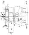
- FIGS. 1 to 3 one is denoted as a whole by 1 Device for removing a weld seam 2 welded pipes, profiles or similar workpieces 3 by means of a cutting tool 4, 4a, 4b during the production-related Feed of the respective workpiece 3 shown.
- a common tool carrier 5 are arranged. Is this respective, the machining of the weld seam elevation 2 Tool 4a worn out, can be done by adjusting the tool holder 5 the next tool 4b in a working position for removal the weld seam elevation 2 are delivered.
- the Tool carrier 5 formed as an approximately cross-shaped turret which a total of four cutting tools 4, 4a, 4b along one Circular path concentric about the axis of rotation 6 of the rotary head are arranged (Figure 3).
- the cutting tools 4, 4a, 4b are planing steels with which the weld seam elevation 2 is special can be removed well and thoroughly.
- the positioning device 7 has a lifting and Rotary drive 8, its axis of rotation 6 and its stroke direction collapse and are vertically oriented. That each in Machining tool 4a located working position the workpiece 3 on the top.
- the tool carrier 5 with the lifting and Rotary drive 8 raised from this first stroke position and brought into a second lifting position in which the worn cutting tool 4a is spaced from the workpiece 3.
- the tool carrier 5 around its Rotation axis 6 can be rotated in the direction of rotation (Pf2, Fig. 3) to deliver new cutting tool 4b to the working position.
- the tool carrier 5 is again in the first stroke position lowered, in which the new cutting tool 4b the workpiece 3 applied to remove the weld seam 2.
- the change of the cutting tool 4 with the Positioning device 7 can automatically and therefore in a short time Time, for example in a few seconds. This makes it fall even with continued feed of the workpiece 3, only a small amount of waste on.
- An exchange of the arranged on the tool carrier 5 cutting tools 4, 4a, 4b is only required when all four tools 4, 4a, 4b are worn.
- the positioning device 7 is operated by a hydraulic motor 11 driven.
- An adjusting spindle 12 is located on the positioning device 7 provided which engages in an inner cavity of the piston rod 10 and with which the vertical position of the tool carrier 5 is adjusted can be. This can, for example, with increasing wear of the cutting tool 4a whose position relative to Surface of the workpiece 3 are readjusted to a constant quality of the workpiece surface when removing the Ensure weld seam elevation 2.
- the individual cutting tools 4, 4a, 4b assigned receptacles 13 for a relative to the axis of rotation 6 of the Turret fixedly positioned engagement element 14 is provided.
- Figure 3 is the arrangement of the receptacles 13 on the tool carrier 5 recognizable and in FIG. 2 the engagement element 14 is shown, that engages in one of the receptacles 13.
- the Engagement element 14 in one of the receptacles 13 becomes the tool carrier 5 with the cutting tool 4a in the working position fixed. This ensures that the cutting Tool 4a is always in the correct position to the Remove excess weld seam 2 thoroughly and an accidental Adjustment of the tool carrier 5 is prevented.
- a sensor 15 For detecting and checking the position of the tool holder 5, a sensor 15 is also provided ( Figure 1, Figure 3). To the Tool carriers 5 are several control elements 16, 16a, 16b for arranged the sensor, the number of control elements 16, 16a, 16b the number of cutting tools 4, 4a, 4b corresponds. Becomes the tool carrier at the beginning of the tool change 5 raised from the first stroke position to the second stroke position, the sensor 15 is controlled by one of the control elements 16a. When the tool carrier 5 rotates about its axis of rotation 6 this control element 16a outside the control range of the Sensor 15, so that the sensor 15 is no longer activated.
- next control element 16b in the control range of the sensor 15 arrives and controls the sensor 15, the next one is cutting tool 4b in the correct working position for Removal of the weld seam elevation 2 and only has to be done Lowering the tool carrier 5 in the first stroke position to the Workpiece 3 can be approximated.
- the tool holder 5 must therefore Change of the cutting tool 4a in each case as far as his Rotation axis 6 are rotated until the next control element 16b controls the sensor 15. This is an additional positioning aid given to the next cutting tool 4b in the correct working position for removing the weld seam elevation Bring 2.
- the sensor 15 can be, for example mechanical, optical or inductive sensor.
- the positioning of the tool carrier 5 and the infeed each a cutting tool 4a is also in the working position simplified by the fact that two directly adjacent cutting Tools 4, 4a, 4b on the tool carrier 5 each have the same distance from each other.
- For the delivery of a next tool 4b is for everyone on the tool carrier 5th arranged cutting tools 4, 4a, 4b the same Positioning movement required so that the control of the Positioning device 7 is simplified.
- Figure 1 it can be seen that the workpiece 3 in Area of the respective machining 3 acting on the workpiece 3 Tool 4a between and on guide rollers 17, 17a managed and held by them.
- Figure 3 shows the device 1 without workpiece 3, so that the lower guide roller 17a on the workpiece when removing the weld seam elevation 2 is visible.
- the lower guide roller 17a can also be designed as a slider.
- the guide rollers 17, 17a are arranged on a holder 18, which in turn is mounted on a device carrier 19.
- the Positioning device 7 is also via a connecting element 20 connected to the device carrier 19.
- the device carrier and thus also the positioning device 7 are one Swivel axis 21 pivotable. By pivoting the positioning device 7 about the pivot axis 21, the position of the in Machining tool 4a located relative to the weld seam elevation 2 of the workpiece 3, always to ensure optimal removal of the weld seam elevation 2.
Abstract
Description
Die Erfindung bezieht sich auf eine Vorrichtung zum Abtragen einer Schweißnahtüberhöhung insbesondere auf der Außenseite von kontinuierlich aus einem Bandmaterial geformten und an den Bandkanten geschweißten Rohren, Profilen oder dergleichen Werkstücken mittels eines spanabhebenden Werkzeuges während des herstellungsbedingten Vorschubs des jeweiligen Werkstückes.The invention relates to a device for removing a Excess weld seam, in particular on the outside of continuously formed from a strip material and at the strip edges welded pipes, profiles or similar workpieces of a cutting tool during production Feed of the respective workpiece.
Beim Längsnahtschweißen von Rohren, Profilen oder dergleichen Werkstücken wird überwiegend das Hochfrequenz-Schweißverfahren eingesetzt. Bei einem derartigen Herstellungsverfahren wird ein Bandmaterial kontinuierlich beispielsweise zu einem Rohr oder Profil geformt. Dabei werden die Bandkanten erwärmt und mittels Stauchrollen zusammengepreßt. Dadurch entsteht auf der Außen- und Innenseite des Werkstückes jeweils eine Schweißnahtüberhöhung, die auf der Außenseite spanabhebend, bevorzugt durch Hobeln, abgetragen wird.For longitudinal seam welding of pipes, profiles or the like Workpieces are mainly made using the high-frequency welding process used. In such a manufacturing process, a Strip material continuously, for example to a tube or profile shaped. The strip edges are heated and by means of compression rolls compressed. This creates on the outside and inside of the workpiece each a weld seam elevation on the The outside is machined, preferably by planing.
Eine Vorrichtung der eingangs genannten Art ist beispielsweise in der DE-OS 23 01 640 beschrieben. Mit der dort beschriebenen Vorrichtung kann ein zu einem Rohr gebogenes Bandmaterial an seinen Bandkanten verschweißt werden. In Vorschubrichtung hinter der Schweißvorrichtung ist ein Abschärfmesser als spanabhebendes Werkzeug zum Abtragen der beim Verschweißen der Bandkanten auf der Außenseite des Rohres entstehenden Schweißnahtüberhöhung angeordnet.A device of the type mentioned at the outset is, for example, in DE-OS 23 01 640 described. With the one described there Device can have a strip material bent into a tube at its Band edges are welded. In the feed direction behind the Welding device is a sharpening knife as a cutting tool to remove the outside of the band edges when welding the resulting weld seam superposition.
Beim Abtragen der Schweißnahtüberhöhung wird das spanabhebende Werkzeug kontinuierlich abgenutzt. Mit einem derart abgenutzten spanabhebenden Werkzeug läßt sich die Schweißnahtüberhöhung nicht mehr optimal abtragen, was zu einer Minderung der Qualität der Oberfläche des Werkstückes führt. Das spanabhebende Werkzeug muß daher in regelmäßigen Abständen gewechselt werden.When removing the weld seam elevation, the cutting Tool worn continuously. With such a worn one Cutting tool cannot be used to increase the weld seam remove more optimally, which leads to a reduction in the quality of the Surface of the workpiece leads. The cutting tool must therefore be changed at regular intervals.
Das Wechseln des spanabhebenden Werkzeuges erfolgt üblicherweise in der Art, daß das Werkzeug von dem Werkstück wegbewegt und von einer Bedienperson ausgetauscht wird. Dieser Wechselvorgang dauert in der Regel mehrere Minuten. Während dieser Zeit wird die Schweißnahtüberhöhung an dem Werkstück nicht abgetragen, so daß ein hoher Ausschuß an nicht bearbeiteten Werkstück-Abschnitten entsteht. Dieser Ausschuß könnte zwar vermieden werden, wenn während dem Austauschen des spanabhebenden Werkzeuges der Vorschub des Werkstückes unterbrochen würde. Dazu müßte jedoch die Produktion bei jedem Werkzeugwechsel angehalten und anschließend neu angefahren werden, was aufwendig und zeitintensiv und somit produktivitätsmindernd ist. Es ist auch möglich, eine zusätzliche Vorrichtung zum Abtragen der Schweißnahtüberhöhung vorzusehen, mit der während dem Wechsel des spanabhebenden Werkzeuges an der ersten Vorrichtung die Schweißnahtüberhöhung an dem Werkstück abgetragen wird. Eine solche zusätzliche Abtrage-Vorrichtung, die lediglich während dem Wechsel des spanabhebenden Werkzeuges der ersten Vorrichtung benötigt wird, verursacht jedoch erhebliche Kosten und konstruktiven Mehraufwand.The cutting tool is usually changed in such a way that the tool moves away from the workpiece and from an operator is replaced. This change process takes usually several minutes. During this time the Excess weld seam on the workpiece is not removed, so that a high scrap of unprocessed workpiece sections arises. This committee could be avoided if during the exchange of the cutting tool the feed of the Workpiece would be interrupted. Production would have to do this, however stopped with every tool change and then started again become what is complex and time-consuming and thus reduces productivity is. It is also possible to have an additional device to provide for the removal of the weld superelevation with which during the change of the cutting tool on the first device the excess weld seam on the workpiece is removed. A such additional ablation device that only during the Change of the cutting tool of the first device required , however, causes considerable cost and constructive Extra effort.
Ein Wechsel des spanabhebenden Werkzeuges bei kontinuierlichem Vorschub des Werkstückes birgt zudem eine erhebliche Unfallgefahr, da das Austauschen des spanabhebenden Werkzeuges in unmittelbarer Nähe des Werkstückes erfolgt, das mit hoher Geschwindigkeit vorgeschoben wird und dessen Schweißnahttemperatur mehrere 100°C betragen kann.A change of the cutting tool with continuous Feeding the workpiece also poses a significant risk of accident, because the replacement of the cutting tool in immediate Closeness of the workpiece is done at high speed is advanced and its weld seam temperature several 100 ° C can be.
Es besteht deshalb die Aufgabe, eine Vorrichtung zum Abtragen einer Schweißnahtüberhöhung der eingangs genannten Art zu schaffen, bei der der Wechsel des spanabhebenden Werkzeuges in kurzer Zeit erfolgen kann, so daß auch bei kontinuierlichem Vorschub des Werkstückes praktisch kein Ausschuß durch unbearbeitete Werkstück-Abschnitte entsteht und bei der der Wechsel des spanabhebenden Werkzeuges ohne Unfallgefahr für eine Bedienperson durchgeführt werden kann.There is therefore the task of a device for removing a To create weld superelevation of the type mentioned at that the cutting tool can be changed in a short time can, so that even with continuous feed of the workpiece practically no rejects due to unprocessed workpiece sections arises and in which the change of the cutting tool without Risk of accident for an operator can be carried out.
Die erfindungsgemäße Lösung dieser Aufgabe besteht insbesondere darin, daß zumindest zwei während des Vorschubes des Werkstückes wechselweise in eine jeweilige Arbeitsposition zum Abtragen der Schweißnahtüberhöhung bringbare spanabhebende Werkzeuge vorgesehen sind. Jeweils eines der spanabhebenden Werkzeuge befindet sich in einer Arbeitsposition, in der es die Schweißnahtüberhöhung abträgt. Wenn dieses Werkzeug soweit abgenutzt ist, daß die Schweißnahtüberhöhung nicht mehr ausreichend gut abgetragen wird, wird dieses Werkzeug aus seiner Arbeitsposition in eine Ruheposition gebracht und statt dessen ein weiteres, nicht abgenutztes spanabhebendes Werkzeug in eine Arbeitsposition gebracht, das dann die Schweißnahtüberhöhung abträgt.The solution to this problem according to the invention consists in particular in that at least two during the feed of the workpiece alternately in a respective working position to remove the Machining tools can be used to increase the weld seam are. One of the cutting tools is located in a working position in which it removes the weld seam elevation. If this tool is worn out so far that the weld seam is excessive is no longer sufficiently well removed, this becomes Tool moved from its working position to a rest position and instead another, not worn, cutting one Tool placed in a working position, which then increases the weld seam removes.
Da die erfindungsgemäße Vorrichtung neben einem im Eingriff befindlichen spanabhebenden Werkzeug noch ein oder mehrere außer Eingriff befindliche Werkzeuge aufweist, die mittels entsprechender Halterungen aber in Arbeitsposition bewegbar sind, während ein bisher benutztes Werkzeug lediglich außer Eingriff zu bewegen ist, kann der Werkzeug-Wechsel besonders schnell erfolgen und verlangt nicht die Demontage des abgenutzten Werkzeuges an der Stelle seiner Arbeitsposition. Vielmehr kann dieses abgenutzte Werkzeug außer Eingriff bewegt und dann zu einer beliebigen Zeit demontiert werden, während ein bisher nicht abgenutztes Werkzeug sich inzwischen im Eingriff befindet. Somit entsteht praktisch kein Ausschuß durch unbearbeitete Werkstück-Abschnitte, auch wenn der Vorschub des Werkstückes während dem Wechsel des spanabhebenden Werkzeuges kontinuierlich weiterläuft.Since the device according to the invention in addition to one cutting tool located one or more except Has engaging tools that by means of appropriate Mounts but are movable in the working position while a the tool previously used can only be moved out of engagement, the tool change can be done very quickly and requires not disassembling the worn tool in the place of it Working position. Rather, this worn tool can save Intervention moved and then dismantled at any time become, while a tool that has not been worn until now engaged. This means that there is practically no committee unprocessed workpiece sections, even if the feed of the Workpiece during the change of the cutting tool continues continuously.
Außerdem kann der Wechsel des spanabhebenden Werkzeuges automatisch erfolgen, so daß zumindest im Bereich der Werkzeuge keine Bedienperson nötig ist. Die Unfallgefahr ist dadurch reduziert. Erst wenn alle an der Vorrichtung angeordneten spanabhebenden Werkzeuge abgenutzt sind, müssen diese ausgetauscht werden. Dies kann beispielsweise in einer Produktionspause erfolgen, so daß für die die spanabhebenden Werkzeuge austauschende Bedienperson keine Unfallgefahr durch den Vorschub des Werkstückes besteht. Je mehr spanabhebende Werkzeuge an der Vorrichtung vorgesehen sind, desto größer ist die Zeitspanne, nach der die Gesamtzahl der Werkzeuge ausgetauscht werden muß.In addition, changing the cutting tool can be done automatically take place so that at least in the area of the tools Operator is necessary. This reduces the risk of accidents. Only when all of the cutting devices arranged on the device Tools are worn out, they must be replaced. This can take place, for example, in a production break, so that for the operator replacing the cutting tools does not There is a risk of accident due to the feed of the workpiece. The more cutting tools are provided on the device, the more the longer the time after which the total number of tools needs to be replaced.
Es ist sogar möglich, das jeweils aus seiner Arbeitsposition in die Ruheposition gebrachte spanabhebende Werkzeug, während es sich in dieser Ruheposition befindet, auszutauschen oder gegebenenfalls nachzuschleifen, wodurch ein kontinuierlicher Betrieb der erfindungsgemäßen Vorrichtung über einen längeren Zeitraum auch mit einer geringen Anzahl von spanabhebenden Werkzeugen, beispielsweise auch mit nur zwei Werkzeugen, möglich ist.It is even possible to move it in from its working position the cutting tool brought in the rest position while it is in this rest position, exchange or, if necessary Regrinding, which ensures continuous operation of the Device according to the invention over a longer period of time with a small number of cutting tools, for example with only two tools.
Es ist vorteilhaft, wenn die spanabhebenden Werkzeuge an einem gemeinsamen Werkzeugträger angeordnet sind, der zum wechselweise Zustellen jeweils eines der Werkzeuge in eine Arbeitsposition mit einer Positioniereinrichtung verbunden ist. Der Wechsel des spanabhebenden Werkzeuges ist so besonders einfach durchführbar. Wenn das abgenutzte spanabhebende Werkzeug aus seiner Arbeitsposition in eine Ruheposition bewegt wird, so wird dadurch gleichzeitig ein weiteres Werkzeug aus einer Ruheposition in seine Arbeitsposition zum Abtragen der Schweißnahtüberhöhung gebracht. Zum Positionieren des Werkzeugträgers genügt dabei eine einzige gemeinsame Positioniereinrichtung. It is advantageous if the cutting tools on one common tool carrier are arranged to alternately Deliver one of the tools to a working position a positioning device is connected. The change of cutting tool is particularly easy to carry out. When the worn cutting tool is out of its working position is moved into a rest position, it is simultaneously a another tool from a rest position to its working position brought to the removal of the weld seam elevation. For positioning of the tool carrier, a single common positioning device is sufficient.
Besonders zweckmäßig ist es, wenn der Werkzeugträger als Drehkopf ausgebildet ist und wenn die spanabhebenden Werkzeuge an dem Drehkopf entlang einer konzentrisch um die Drehachse des Drehkopfes verlaufenden Kreisbahnen angeordnet sind. Der Wechsel des spanabhebenden Werkzeuges beziehungsweise das Zustellen jeweils eines neuen Werkzeuges in eine Arbeitsposition kann so durch eine einfache Drehbewegung des Drehkopfes erfolgen. Der konstruktive Aufwand für die Positioniereinrichtung ist somit reduziert. Trotzdem ist eine präzise Zustellung jeweils eines spanabhebenden Werkzeugs in eine Arbeitsposition möglich.It is particularly useful if the tool carrier as a turret is formed and when the cutting tools on the rotary head along a concentric around the axis of rotation of the turret running circular paths are arranged. The change of cutting tool or the delivery in each case of a new tool in a working position can simple rotary movement of the turret. The constructive The effort for the positioning device is thus reduced. Nevertheless, a precise delivery is always a cutting Possible in a working position.
Es ist zudem zweckmäßig, wenn die Positioniereinrichtung einen Hub- und Drehantrieb zum wechselweise Zustellen jeweils eines der spanabhebenden Werkzeuge in eine Arbeitsposition aufweist. Das sich in Arbeitsposition befindende spanabhebende Werkzeug kann dann zum Wechsel des Werkzeuges zunächst von dem Werkstück durch eine Hubbewegung beabstandet werden und anschließend kann durch eine Drehbewegung und anschließende, der Hubbewegung entgegengesetzte Zustellbewegung des Werkzeugträgers das nächste spanabhebende Werkzeug in Arbeitsposition gebracht werden. Die spanabhebenden Werkzeuge sind so während der Drehbewegung des Werkzeugträgers von dem Werkstück beabstandet, so daß eine Beschädigung der Oberfläche des Werkstückes während dem Werkzeug-Wechsel vermieden ist.It is also useful if the positioning device has a lifting and Rotary actuator for alternately feeding one of the has cutting tools in a working position. That I in the working position cutting tool can then to First change the tool from the workpiece to a Stroke movement can be spaced and then by a Rotary movement and subsequent, opposite to the lifting movement Infeed movement of the tool carrier the next cutting Tool in the working position. The cutting Tools are so during the rotational movement of the tool holder spaced from the workpiece, causing damage to the surface of the workpiece during tool change is avoided.
Eine besonders günstige Ausführungsform sieht dabei vor, daß der Drehkopf mittels des Hub- und Drehantriebs zwischen einer ersten Hubposition, in der jeweils eines der an dem Drehkopf angeordneten spanabhebenden Werkzeuge an das zu bearbeitende Werkstück angenähert ist und dieses beaufschlagt und einer zweiten Hubposition, in der dieses spanabhebende Werkzeug von dem Werkstück beabstandet ist, verstellbar ist und daß der Drehkopf in der zweiten Hubposition zur Zustellung eines anderen der an dem Drehkopf angeordneten spanabhebenden Werkzeuge an das Werkstück mittels des Hub- und Drehantriebs um seine Drehachse drehbar ist. A particularly favorable embodiment provides that the Turret by means of the lifting and rotating drive between a first Stroke position, in each of which is arranged on the rotary head cutting tools on the workpiece to be machined is approximated and this is applied and a second stroke position, in which this cutting tool is spaced from the workpiece is adjustable and that the rotary head in the second stroke position for the delivery of another one arranged on the rotary head cutting tools to the workpiece by means of the lifting and Rotary drive is rotatable about its axis of rotation.
Dabei kann die Drehachse des Drehkopfes quer zur Vorschubrichtung des Werkstückes orientiert sein.The axis of rotation of the rotary head can be transverse to the feed direction of the workpiece.
Es ist zudem zweckmäßig, wenn das jeweilige, sich in Arbeitsposition befindliche spanabhebende Werkzeug das Werkstück auf seiner oberen Seite beaufschlagt und wenn die Hubrichtung des Hub- und Drehantriebes vertikal orientiert ist. Das abgenutzte spanabhebende Werkzeug beziehungsweise der gesamte Werkzeugträger kann dann zum Wechsel des spanabhebenden Werkzeuges angehoben werden, bevor durch Drehung des Werkzeugträgers die Zustellung des nächsten spanabhebenden Werkzeuges erfolgt. Anschließend wird dieses neue spanabhebende Werkzeug beziehungsweise der Werkzeugträger abgesenkt, bis das neue Werkzeug das Werkstück oberseitig beaufschlagt und so die Schweißnahtüberhöhung mit dem neuen Werkzeug abgetragen werden kann.It is also useful if the particular one is in a working position cutting tool located the workpiece on its upper Side acted upon and if the stroke direction of the lifting and rotary drive is oriented vertically. The worn cutting tool or the entire tool carrier can then be changed of the cutting tool are raised before turning of the tool carrier the delivery of the next cutting Tool takes place. Then this new cutting Tool or the tool holder lowered until the new one Tool applied to the workpiece on the top and so the Excess weld seam can be removed with the new tool.
Eine konstruktiv und für die Handhabung günstige Ausführungsform kann dabei darin bestehen, daß die Drehachse des Drehkopfes vertikal orientiert ist. Sind sowohl die Hubrichtung des Hub- und Drehantriebes als auch die Drehachse des Drehkopfes vertikal orientiert, so ist die Konstruktion des Hub- und Drehantriebes vereinfacht, da Hub- und Drehachse zusammenfallen können. Beispielsweise kann der Hub- und Drehantrieb durch einen Hub- und Drehzylinder gebildet sein, dessen Kolbenstange einerseits für eine Hub- und andererseits für eine Drehbewegung ausgebildet ist. Der Hub- und Drehantrieb läßt sich so besonders platzsparend konstruieren. Außerdem kann das Werkstück auf einer unterhalb des Werkstückes angeordneten Werkstück-Führung aufliegen und wird dabei trotz der oberseitigen Beaufschlagung durch das spanabhebende Werkzeug nicht aus dieser Position bewegt. Es ist gegebenenfalls sogar möglich, das spanabhebende Werkzeug mit einer dosierbaren Kraft an das Werkstück anzudrücken und dabei auch den Werkstoff des Werkstückes entsprechend zu berücksichtigen.A constructive and easy to handle embodiment can consist in the fact that the axis of rotation of the rotary head is vertical is oriented. Are both the stroke direction of the stroke and Rotary drive and the axis of rotation of the rotary head vertically is the design of the lifting and rotary drive simplified because the stroke and rotation axes can coincide. For example, the lifting and rotary drive can be operated by a lifting and Be formed rotary cylinder, the piston rod on the one hand for a lifting and on the other hand is designed for a rotary movement. The lifting and rotary drive can be particularly space-saving to construct. In addition, the workpiece can be placed on a below the Workpiece arranged workpiece guide lie on it and will in spite of the top loading by the machining company Tool not moved from this position. It may be even possible the cutting tool with a meterable Pushing force against the workpiece and also the material the workpiece accordingly.
Es kann zweckmäßig sein, wenn die Positioniereinrichtung eine Einstellspindel zum automatischen oder manuellen Justieren des Abstandes des jeweiligen spanabhebenden Werkzeugs von der Oberfläche des Werkstückes in der ersten Hubposition des Hub- und Drehantriebes aufweist. Bei zunehmender Abnutzung des spanabhebenden Werkzeuges und einem damit verbundenen Nachlassen der spanabhebenden Wirkung dieses Werkzeuges kann das spanabhebende Werkzeug mit der Einstellspindel der Oberfläche des Werkstückes angenähert werden, um so dem Nachlassen der spanabhebenden Wirkung entgegenzuwirken und eine gleichbleibende Qualität der Oberfläche des Werkstückes sicherzustellen. Die Zeitspanne zwischen dem Wechsel zweier spanabhebender Werkzeuge kann so gegebenenfalls verlängert werden. Jedes einzelne spanabhebende Werkzeug kann über einen längeren Zeitraum benutzt werden, wodurch insgesamt weniger Werkzeuge benötigt und somit Kosten eingespart werden.It can be useful if the positioning device is a Adjustment spindle for automatic or manual adjustment of the Distance of the respective cutting tool from the surface of the workpiece in the first stroke position of the lifting and rotary drive having. With increasing wear of the cutting tool and an associated decrease in the machining effect This tool can be used with the cutting tool Adjusting spindle to be approximated to the surface of the workpiece, so as to counteract the deterioration of the cutting effect and a constant quality of the surface of the workpiece ensure. The time span between the change of two cutting tools can be extended if necessary. Each individual cutting tool can last longer Period are used, which means that fewer tools are required overall and thus costs can be saved.
Um sicherzustellen, daß beim Zustellen eines neuen spanabhebenden Werkzeuges dieses Werkzeug in die richtige Arbeitsposition zum Abtragen der Schweißnahtüberhöhung gelangt, ist es vorteilhaft, wenn an dem Drehkopf mehrere, den einzelnen spanabhebenden Werkzeugen zugeordnete Aufnahmen für ein relativ zur Drehachse des Drehkopfes fest positioniertes Eingriffselement vorgesehen sind, wobei das Eingriffselement bei in Arbeitsposition befindlichem spanabhebenden Werkzeug zur Fixierung des Drehkopfes in die dem jeweiligen spanabhebenden Werkzeug zugeordnete Aufnahme eingreift. Dadurch ist sichergestellt, daß der Drehkopf beim Werkzeugwechsel um das richtige Maß gedreht wird, um das nächste spanabhebende Werkzeug zuzustellen und exakt in seine Arbeitsposition zum Abtragen der Schweißnahtüberhöhung zu bringen. Desweiteren ist verhindert, daß der Drehkopf versehentlich aus dieser Position verschwenkt wird, wodurch die Schweißnahtüberhöhung des Werkstückes nicht mehr zuverlässig abgetragen werden könnte. Das Eingriffselement kann beispielsweise eine Rastvorrichtung oder ein Indexzylinder sein.To ensure that when delivering a new cutting This tool in the correct working position Removal of the weld superelevation, it is advantageous if several, the individual cutting tools on the rotary head assigned recordings for a relative to the axis of rotation of the rotary head firmly positioned engaging element are provided, the Engagement element with cutting in the working position Tool for fixing the rotary head in the respective cutting tool engages associated recording. Thereby it is ensured that the turret around the tool change correct dimension is turned around the next cutting tool to deliver and exactly in its working position to remove the To bring weld seam elevation. Furthermore, it is prevented that the rotary head is accidentally swiveled out of this position, whereby the weld seam elevation of the workpiece is no longer could be removed reliably. The engaging element can for example, a locking device or an index cylinder.
Es kann zudem zweckmäßig sein, wenn zumindest ein Sensor zum Erfassen der Position des Werkzeugträgers vorgesehen ist. Mit dem Sensor kann kontrolliert werden, ob der Werkzeugträger beim Wechsel des spanabhebenden Werkzeuges richtig positioniert wurde und ob sich nach dem Zustellen eines neuen Werkzeuges dieses neue Werkzeug exakt in seiner Arbeitsposition zum Abtragen der Schweißnahtüberhöhung befindet. Wird ein Positionierungsfehler erkannt, so kann beispielsweise ein Signal gegeben und/oder der Vorschub des Werkstückes gestoppt werden, um unnötigen Ausschuß zu vermeiden.It can also be useful if at least one sensor for detection the position of the tool carrier is provided. With the sensor can be checked whether the tool carrier when changing the cutting tool has been positioned correctly and whether after the delivery of a new tool this new tool exactly in its working position for removing the weld seam elevation located. If a positioning error is detected, then can be given a signal and / or the feed of the Workpiece to be stopped to avoid unnecessary rejects.
Die Zustellung der spanabhebenden Werkzeuge sowie deren Positionierung wird vereinfacht, wenn einander in Zustellrichtung benachbarte spanabhebende Werkzeuge an dem Drehkopf jeweils denselben Abstand zueinander haben. Die zum Wechseln des spanabhebenden Werkzeuges erforderliche Positionierbewegung ist so für alle Werkzeuge stets dieselbe, so daß die Steuerung der Positioniereinrichtung vereinfacht ist.The delivery of the cutting tools and their positioning is simplified if adjacent to each other in the feed direction cutting tools on the rotary head each the same distance to each other. Those for changing the cutting tool The required positioning movement is always the same for all tools the same, so that the control of the positioning device is simplified is.
Eine besonders günstige Ausführungsform sieht vor, daß an dem Drehkopf vier spanabhebende Werkzeuge angeordnet sind. Mit insgesamt vier spanabhebenden Werkzeugen läßt sich über einen ausreichenden Zeitraum die Schweißnahtüberhöhung an dem Werkstück abtragen, bevor alle Werkzeuge abgenutzt sind und ausgetauscht werden müssen. Dieser Austausch der spanabhebenden Werkzeuge kann beispielsweise in einer Produktionspause bei Anlagenstillstand erfolgen. Der Wechsel der spanabhebenden Werkzeuge kann dann ohne Zeitdruck und ohne Ausschußproduktion durchgeführt werden. Außerdem besteht bei Anlagenstillstand für die die Werkzeuge austauschende Bedienperson keine Unfallgefahr. Es ist aber auch möglich, abgenutzte Werkzeuge während der Produktion auszutauschen, weil bei einer derartigen Anzahl von Werkzeugen zumindest das dem in Eingriff befindlichen Werkzeug auf einer Durchmesserachse des Drehkopfes gegenüberliegende Werkzeug von dem Werkstück einen relativ großen Abstand einnimmt, so daß ein an dieser Stelle durchgeführter Werkzeugwechsel ebenfalls problemlos durchgeführt werden kann.A particularly favorable embodiment provides that the Turret four cutting tools are arranged. With A total of four cutting tools can be operated using one sufficient time to increase the weld seam on the workpiece remove before all tools are worn and replaced have to. This exchange of cutting tools can for example during a production break when the plant is down respectively. The change of the cutting tools can then without Time pressure and can be carried out without rejects. Moreover exists when the system is at a standstill for those replacing the tools Operator no risk of accident. But it is also possible to get worn out Exchange tools during production because at one Such a number of tools at least that the located tool on a diameter axis of the rotary head opposite tool from the workpiece a relatively large Takes up distance, so that a carried out at this point Tool changes can also be carried out easily.
Dabei ist es zweckmäßig, wenn der Drehkopf kreuzförmig ausgebildet ist. Die spanabhebenden Werkzeuge lassen sich jeweils an den freien Enden des kreuzförmigen Drehkopfes anordnen, so daß zwei direkt benachbarte Werkzeuge jeweils denselben Abstand zueinander haben. Der Drehkopf als solches läßt sich zudem mit einem reduzierten Materialaufwand herstellen.It is useful if the turret is cruciform is. The cutting tools can be used on the free Arrange the ends of the cross-shaped turret so that two directly neighboring tools have the same distance from each other. The turret as such can also be reduced Manufacture material costs.
Das Abtragen der Schweißnahtüberhöhung kann besonders gründlich erfolgen, wenn als spanabhebendes Werkzeug jeweils ein Hobelwerkzeug vorgesehen ist. Mit einem Hobelwerkzeug läßt sich die Schweißnahtüberhöhung im Vergleich zu einem Schneid-, Schleif- oder dergleichen Werkzeug besonders gründlich und gleichmäßig abtragen. Als Hobelwerkzeug kann dabei beispielsweise ein Hobelstahl verwendet werden.The removal of the weld seam elevation can be particularly thorough take place when a planing tool is used as the cutting tool is provided. This can be done with a planing tool Weld seam elevation compared to a cutting, grinding or remove the same tool particularly thoroughly and evenly. A planing steel, for example, can be used as a planing tool become.
Um ein gleichmäßiges Abtragen der Schweißnahtüberhöhung sicherzustellen und somit eine gleichmäßige Oberfläche des Werkstückes zu erreichen, ist es zweckmäßig, wenn das Werkstück zumindest im Bereich des jeweiligen, das Werkstück beaufschlagenden spanabhebenden Werkzeugs zwischen und/oder auf Führungsrollen und/oder Gleitführungen geführt und von diesen gehalten ist. Das Werkstück ist von diesen Führungsrollen und/oder Gleitführungen absolut ruhig gehalten, so daß beim Vorschub des Werkstückes und beim Abtragen der Schweißnahtüberhöhung keine Vibrationen entstehen und so eine optimale Oberflächenqualität beim Abtragen der Schweißnahtüberhöhung erreicht wird.To ensure even removal of the weld seam elevation and thus a uniform surface of the workpiece To achieve, it is useful if the workpiece at least in Area of the respective metal-cutting machined workpiece Tool between and / or on guide rollers and / or Slideways guided and is held by these. The workpiece is absolutely quiet of these guide rollers and / or sliding guides held so that when feeding the workpiece and when removing no vibrations occur when the weld seam is raised and so one optimal surface quality when removing the weld seam elevation is achieved.
Ein weiterführender Erfindungsgedanke kann darin bestehen, daß zumindest zwei in Vorschubrichtung voneinander beabstandete Werkzeugträger mit jeweils wenigstens zwei wahl- oder wechselweise in Arbeitsposition zustellbaren spanabhebenden Werkzeugen vorgesehen sind. Es ist möglich, an jedem der Werkzeugträger jeweils ein spanabhebendes Werkzeug in Arbeitsposition zu bringen, so daß mehrere hintereinander angeordnete Werkzeuge gleichzeitig in einer Arbeitsposition sind und das Werkstück beaufschlagen. Die Schweißnahtüberhöhung kann dadurch in wenigstens zwei Schritten abgetragen werden, indem ein sie zuerst beaufschlagendes Werkzeug nur einen Teil und das in Vorschubrichtung dahinter befindliche nächste Werkzeug einen weiteren Teil oder den Rest der Schweißnahtüberhöhung abträgt. Dies kann vor allem bei relativ großen Schweißnähten und Schweißnahtüberhöhungen günstig sein. Sind die in Vorschubrichtung hintereinander in Eingriff befindlichen spanabhebenden Werkzeuge stumpf oder abgenutzt, können sie jeweils in der erfindungsgemäßen vorbeschriebenen Weise, auch während der weiteren Produktion, gewechselt werden.A further inventive idea can consist in that at least two spaced apart in the feed direction Tool carriers with at least two each alternatively or alternatively Cutting tools that can be set in the working position are. It is possible to have one on each of the tool carriers to bring cutting tool into working position, so that several tools arranged one behind the other simultaneously in one Are working position and apply the workpiece. The This can increase the weld seam in at least two steps can be removed by using a tool first only a part and the one behind it in the feed direction next tool another part or the rest of the weld seam elevation removes. This can be especially the case with relatively large ones Weld seams and weld seam elevations can be cheap. Are the in engagement in the feed direction cutting tools blunt or worn, they can each in the manner described above, also during the further production.
Nachstehend ist ein Ausführungsbeispiel der Erfindung anhand der Zeichnung näher beschrieben.Below is an embodiment of the invention based on the Drawing described in more detail.
Es zeigt in zum Teil schematisierter Darstellung:
- Fig.1
- eine teilweise im Schnitt gehaltene Frontansicht einer erfindungsgemäßen Vorrichtung zum Abtragen einer Schweißnahtüberhöhung mit einem Werkzeugträger, der mit einer Positioniereinrichtung verbunden ist sowie mit einem Rohr als Werkstück, das auf und zwischen Führungsrollen gehalten ist, wobei die Blickrichtung der Vorschubrichtung des Werkstückes entspricht,
- Fig.2
- eine Seitenansicht der Vorrichtung gemäß Figur 1 und
- Fig.3
- eine Draufsicht der Vorrichtung gemäß Figur 1 und 2.
- Fig. 1
- FIG. 2 shows a front view, partly in section, of a device according to the invention for removing a weld seam elevation with a tool carrier which is connected to a positioning device and with a tube as a workpiece which is held on and between guide rollers, the viewing direction corresponding to the feed direction of the workpiece,
- Fig. 2
- a side view of the device of Figure 1 and
- Fig. 3
- 2 shows a top view of the device according to FIGS. 1 and 2.
In den Figuren 1 bis 3 ist jeweils eine im ganzen mit 1 bezeichnete
Vorrichtung zum Abtragen einer Schweißnahtüberhöhung 2 an
geschweißten Rohren, Profilen oder dergleichen Werkstücken 3 mittels
eines spanabhebenden Werkzeugs 4, 4a, 4b während des herstellungsbedingten
Vorschubes des jeweiligen Werkstückes 3 dargestellt.In FIGS. 1 to 3, one is denoted as a whole by 1
Device for removing a weld seam 2
welded pipes, profiles or
Beim Längsnahtschweißen des Werkstückes 3 entsteht eine Schweißnahtüberhöhung
2, die mit einem spanabhebenden Werkzeug 4a abgetragen
wird. Das spanabhebende Werkzeug 4a wird durch das Abtragen der
Schweißnahtüberhöhung 2 abgenutzt, so daß dieses regelmäßig
ausgewechselt werden muß. Während dem Wechsel des Werkzeuges 4a
wird die Schweißnahtüberhöhung 2 nicht abgetragen, so daß bedingt
durch den fortlaufenden Vorschub des Werkstückes 3 in Richtung des
Pfeiles Pf1 (Fig. 2, 3) Ausschuß durch nicht bearbeitete Abschnitte
des Werkstückes 3 entsteht. In Figur 1 verläuft die Vorschubrichtung
des Werkstückes 3 in die Zeichenebene hinein.When the
Um den Wechsel des spanabhebenden Werkzeugs 4a automatisch ablaufen
zu lassen und die Zeit für den Wechsel möglichst gering zu halten,
sind mehrere spanabhebende Werkzeuge 4, 4a, 4b vorgesehen, die an
einem gemeinsamen Werkzeugträger 5 angeordnet sind. Ist das
jeweilige, die Schweißnahtüberhöhung 2 abtragende spanabhebende
Werkzeug 4a abgenutzt, so kann durch Verstellen des Werkzeugträgers
5 das nächste Werkzeuge 4b in eine Arbeitsposition zum Abtragen
der Schweißnahtüberhöhung 2 zugestellt werden.To automatically change the
Bei der gezeigten Ausführungsform der Vorrichtung 1 ist der
Werkzeugträger 5 als etwa kreuzförmiger Drehkopf ausgebildet, an
dem insgesamt vier spanabhebende Werkzeuge 4, 4a, 4b entlang einer
konzentrisch um die Drehachse 6 des Drehkopfes verlaufenden Kreisbahn
angeordnet sind (Figur 3). Die spanabhebenden Werkzeuge 4, 4a, 4b
sind Hobelstähle, mit denen die Schweißnahtüberhöhung 2 besonders
gut und gründlich abgetragen werden kann. Zum Zustellen jeweils
eines spanabhebenden Werkzeuges 4a in eine Arbeitsposition ist der
Werkzeugträger 5 mit einer Positioniereinrichtung 7 verbunden
(Figur 1). Die Positioniereinrichtung 7 weist einen Hub- und
Drehantrieb 8 auf, dessen Drehachse 6 und dessen Hubrichtung
zusammenfallen und vertikal orientiert sind. Das sich jeweils in
Arbeitsposition befindende spanabhebende Werkzeug 4a beaufschlagt
das Werkstück 3 oberseitig. Zum Auswechseln dieses spanabhebenden
Werkzeuges 4a und zum Zustellen eines neuen spanabhebenden Werkzeuges
4b in die Arbeitsposition kann der Werkzeugträger 5 mit dem Hub- und
Drehantrieb 8 aus dieser ersten Hubposition heraus angehoben
und in eine zweite Hubposition gebracht werden, in der das abgenutzte
spanabhebende Werkzeug 4a von dem Werkstück 3 beabstandet ist. In
dieser zweiten Hubposition kann der Werkzeugträger 5 um seine
Drehachse 6 in Drehrichtung (Pf2, Fig. 3) gedreht werden, um ein
neues spanabhebendes Werkzeug 4b in die Arbeitsposition zuzustellen.
Danach wird der Werkzeugträger 5 wieder in die erste Hubposition
abgesenkt, in der das neue spanabhebende Werkzeug 4b das Werkstück
3 zur Abtragung der Schweißnahtüberhöhung 2 beaufschlagt. Durch
das Anheben des Werkzeugträgers 5 beziehungsweise dem Abheben des
spanabhebenden Werkzeuges 4a von dem Werkstück 3 ist vermieden,
daß das Werkstück 3 beim Drehen des Werkzeugträgers 5 beschädigt
wird. Der Wechsel des spanabhebenden Werkzeuges 4 mit der
Positioniereinrichtung 7 kann automatisch und dadurch in kurzer
Zeit, beispielsweise in wenigen Sekunden erfolgen. Dadurch fällt
auch bei anhaltendem Vorschub des Werkstückes 3 nur wenig Ausschuß
an. Ein Austauschen der an dem Werkzeugträger 5 angeordneten
spanabhebenden Werkzeuge 4, 4a, 4b ist erst erforderlich, wenn alle
vier Werkzeuge 4, 4a, 4b abgenutzt sind.In the embodiment of the
Gemäß Figur 1 ist der Hub- und Drehantrieb 8 durch einen Hub- und
Drehzylinder mit einem Zylindermantel 9 und einer Kolbenstange 10
gebildet. Die Positioniereinrichtung 7 wird von einem Hydraulikmotor
11 angetrieben.According to Figure 1, the lifting and
An der Positioniereinrichtung 7 ist eine Einstellspindel 12
vorgesehen, die in eine Innenhöhlung der Kolbenstange 10 eingreift
und mit der die vertikale Position des Werkzeugträgers 5 justiert
werden kann. Dadurch kann beispielsweise bei zunehmender Abnutzung
des spanabhebenden Werkzeuges 4a dessen Position relativ zur
Oberfläche des Werkstückes 3 nachjustiert werden, um eine
gleichbleibende Qualität der Werkstückoberfläche beim Abtragen der
Schweißnahtüberhöhung 2 sicherzustellen.An adjusting
An dem Werkzeugträger 5 beziehungsweise an dem Drehkopf sind
mehrere, den einzelnen spanabhebenden Werkzeugen 4, 4a, 4b
zugeordnete Aufnahmen 13 für ein relativ zur Drehachse 6 des
Drehkopfes fest positioniertes Eingriffselement 14 vorgesehen. In
Figur 3 ist die Anordnung der Aufnahmen 13 an dem Werkzeugträger
5 erkennbar und in Figur 2 ist das Eingriffselement 14 dargestellt,
das in eine der Aufnahmen 13 eingreift. Durch das Eingreifen des
Eingriffselements 14 in eine der Aufnahmen 13 wird der Werkzeugträger
5 bei in Arbeitsposition befindlichem spanabhebenden Werkzeug 4a
fixiert. Dadurch ist sichergestellt, daß sich das spanabhebende
Werkzeug 4a stets in der richtigen Position befindet, um die
Schweißnahtüberhöhung 2 gründlich abzutragen und ein versehentliches
Verstellen des Werkzeugträgers 5 ist verhindert.Are on the
Zum Erfassen und zur Kontrolle der Position des Werkzeugträgers
5 ist zudem ein Sensor 15 vorgesehen (Figur 1, Figur 3). An dem
Werkzeugträger 5 sind mehrere Ansteuerelemente 16, 16a, 16b für
den Sensor angeordnet, wobei die Anzahl der Ansteuerelemente 16,
16a, 16b der Anzahl der spanabhebenden Werkzeuge 4, 4a, 4b
entspricht. Wird zu Beginn des Werkzeugwechsels der Werkzeugträger
5 aus der ersten Hubposition in die zweite Hubposition angehoben,
so wird der Sensor 15 von einem der Ansteuerelemente 16a angesteuert.
Beim Drehen des Werkzeugträgers 5 um dessen Drehachse 6 gelangt
dieses Ansteuerelement 16a außerhalb des Ansteuerbereiches des
Sensors 15, so daß der Sensor 15 nicht mehr angesteuert wird. Wenn
das nächste Ansteuerelement 16b in den Ansteuerbereich des Sensors
15 gelangt und den Sensor 15 ansteuert, befindet sich das nächste
spanabhebende Werkzeug 4b in der richtigen Arbeitsposition zum
Abtragen der Schweißnahtüberhöhung 2 und muß nur noch durch
Absenken des Werkzeugträgers 5 in die erste Hubposition an das
Werkstück 3 angenähert werden. Der Werkzeugträger 5 muß also beim
Wechsel des spanabhebenden Werkzeugs 4a jeweils soweit um seine
Drehachse 6 gedreht werden, bis das jeweils nächste Ansteuerelement
16b den Sensor 15 ansteuert. Somit ist eine zusätzliche Positionierhilfe
gegeben, um das jeweils nächste spanabhebende Werkzeug
4b in die richtige Arbeitsposition zum Abtragen der Schweißnahtüberhöhung
2 zu bringen. Der Sensor 15 kann beispielsweise ein
mechanischer, optischer oder induktiver Sensor sein. For detecting and checking the position of the
Die Positionierung des Werkzeugträgers 5 und die Zustellung jeweils
eines spanabhebenden Werkzeuges 4a in die Arbeitsposition ist auch
dadurch vereinfacht, daß jeweils zwei direkt benachbarte spanabhebende
Werkzeuge 4, 4a, 4b an dem Werkzeugträger 5 jeweils
denselben Abstand zueinander haben. Für die Zustellung eines
nächsten Werkzeuges 4b ist für alle der an dem Werkzeugträger 5
angeordneten spanabhebenden Werkzeuge 4, 4a, 4b die gleiche
Positionierbewegung erforderlich, so daß die Steuerung der
Positioniereinrichtung 7 vereinfacht ist.The positioning of the
Insbesondere in Figur 1 ist zu erkennen, daß das Werkstück 3 im
Bereich des jeweiligen das Werkstück 3 beaufschlagenden spanabhebenden
Werkzeugs 4a zwischen und auf Führungsrollen 17, 17a
geführt und von diesen gehalten ist. Dadurch ist das Werkstück 3
besonders ruhig und vibrationsfrei gehalten und geführt, so daß
die Abtragung der Schweißnahtüberhöhung 2 besonders gründlich
erfolgen kann und eine hohe Oberflächenqualität des fertigen
Werkstückes 3 erzielt werden kann. Figur 3 zeigt die Vorrichtung
1 ohne Werkstück 3, so daß auch die untere Führungsrolle 17a, auf
der das Werkstück beim Abtragen der Schweißnahtüberhöhung 2
aufliegt, zu erkennen ist. Die untere Führungsrolle 17a kann auch
als Gleitstück ausgeführt sein.In particular in Figure 1 it can be seen that the
Die Führungsrollen 17, 17a sind an einer Halterung 18 angeordnet,
die ihrerseits auf einem Vorrichtungsträger 19 montiert ist. Die
Positioniereinrichtung 7 ist ebenfalls über ein Verbindungselement
20 mit dem Vorrichtungsträger 19 verbunden. Der Vorrichtungsträger
und somit auch die Positioniereinrichtung 7 sind dabei um eine
Schwenkachse 21 verschwenkbar. Durch Verschwenken der Positioniereinrichtung
7 um die Schwenkachse 21 läßt sich die Lage des sich in
Arbeitsposition befindenden spanabhebenden Werkzeugs 4a relativ
zur Schweißnahtüberhöhung 2 des Werkstückes 3 variieren, um stets
ein optimales Abtragen der Schweißnahtüberhöhung 2 sicherzustellen.The
Claims (17)
Applications Claiming Priority (2)
| Application Number | Priority Date | Filing Date | Title |
|---|---|---|---|
| DE1997153102 DE19753102C1 (en) | 1997-11-29 | 1997-11-29 | Apparatus for removal of a weld seam protrusion |
| DE19753102 | 1997-11-29 |
Publications (2)
| Publication Number | Publication Date |
|---|---|
| EP0919299A2 true EP0919299A2 (en) | 1999-06-02 |
| EP0919299A3 EP0919299A3 (en) | 2000-02-23 |
Family
ID=7850297
Family Applications (1)
| Application Number | Title | Priority Date | Filing Date |
|---|---|---|---|
| EP98120733A Withdrawn EP0919299A3 (en) | 1997-11-29 | 1998-10-31 | Device for removing raised weld bead |
Country Status (2)
| Country | Link |
|---|---|
| EP (1) | EP0919299A3 (en) |
| DE (1) | DE19753102C1 (en) |
Cited By (2)
| Publication number | Priority date | Publication date | Assignee | Title |
|---|---|---|---|---|
| DE102005022244A1 (en) * | 2005-05-13 | 2006-11-16 | Eroform Edelstahl Gmbh | Guidance and deformation system |
| WO2008014740A1 (en) | 2006-08-01 | 2008-02-07 | Eroform Edelstahl Gmbh | Suspension for a laser welding unit |
Families Citing this family (1)
| Publication number | Priority date | Publication date | Assignee | Title |
|---|---|---|---|---|
| DE20003048U1 (en) * | 2000-02-19 | 2000-05-25 | Horn Gmbh Maschbau | Plastering device, in particular welding bead cleaning machine |
Citations (5)
| Publication number | Priority date | Publication date | Assignee | Title |
|---|---|---|---|---|
| DE936084C (en) * | 1953-04-16 | 1955-12-07 | Kronprinz Ag | Device for the production of pipes from longitudinally welded output pipes to be subjected to a drawing process with a device for removing the weld burr |
| DE1013606B (en) * | 1955-04-04 | 1957-08-14 | Mannesmann Ag | Device for removing the inner ridge of longitudinally welded pipes |
| US2959842A (en) * | 1957-12-06 | 1960-11-15 | Bundy Tubing Co | Tube scarfing device |
| FR2475438A3 (en) * | 1980-02-07 | 1981-08-14 | Vanzetti Metalloceramica | Tool for removing longitudinal weld beads on tubes - comprises cutting plate and counter-plate mounted on hand-tool |
| EP0158692A1 (en) * | 1984-04-18 | 1985-10-23 | Schweissindustrie Oerlikon Bührle AG | Method and device for machining the longitudinal weld seam of a moving pipe |
Family Cites Families (1)
| Publication number | Priority date | Publication date | Assignee | Title |
|---|---|---|---|---|
| BE793124A (en) * | 1972-06-23 | 1973-04-16 | Wheeling Pittsburgh Steel Corp | METAL PROTECTIVE TUBES FOR ELECTRICAL PIPES |
-
1997
- 1997-11-29 DE DE1997153102 patent/DE19753102C1/en not_active Expired - Fee Related
-
1998
- 1998-10-31 EP EP98120733A patent/EP0919299A3/en not_active Withdrawn
Patent Citations (5)
| Publication number | Priority date | Publication date | Assignee | Title |
|---|---|---|---|---|
| DE936084C (en) * | 1953-04-16 | 1955-12-07 | Kronprinz Ag | Device for the production of pipes from longitudinally welded output pipes to be subjected to a drawing process with a device for removing the weld burr |
| DE1013606B (en) * | 1955-04-04 | 1957-08-14 | Mannesmann Ag | Device for removing the inner ridge of longitudinally welded pipes |
| US2959842A (en) * | 1957-12-06 | 1960-11-15 | Bundy Tubing Co | Tube scarfing device |
| FR2475438A3 (en) * | 1980-02-07 | 1981-08-14 | Vanzetti Metalloceramica | Tool for removing longitudinal weld beads on tubes - comprises cutting plate and counter-plate mounted on hand-tool |
| EP0158692A1 (en) * | 1984-04-18 | 1985-10-23 | Schweissindustrie Oerlikon Bührle AG | Method and device for machining the longitudinal weld seam of a moving pipe |
Cited By (5)
| Publication number | Priority date | Publication date | Assignee | Title |
|---|---|---|---|---|
| DE102005022244A1 (en) * | 2005-05-13 | 2006-11-16 | Eroform Edelstahl Gmbh | Guidance and deformation system |
| DE102005022244B4 (en) * | 2005-05-13 | 2007-07-19 | Eroform Edelstahl Gmbh | Guiding and deformation system, its use and method of making welded pipes |
| US8829384B2 (en) | 2005-05-13 | 2014-09-09 | Wuppermann Edelstahltechnik Gmbh | Guiding and shaping system |
| WO2008014740A1 (en) | 2006-08-01 | 2008-02-07 | Eroform Edelstahl Gmbh | Suspension for a laser welding unit |
| DE102006035702A1 (en) * | 2006-08-01 | 2008-02-21 | Eroform Edelstahl Gmbh | Suspension for a laser welding machine |
Also Published As
| Publication number | Publication date |
|---|---|
| EP0919299A3 (en) | 2000-02-23 |
| DE19753102C1 (en) | 1999-01-28 |
Similar Documents
| Publication | Publication Date | Title |
|---|---|---|
| DE10234707B4 (en) | Method and device for grinding a rotationally symmetrical machine component | |
| EP2082813B1 (en) | Mechanical device for maintenance and/or cleaning of support strips of a work piece support | |
| DE69732808T2 (en) | grinder | |
| DE2828168A1 (en) | NUMERICALLY CONTROLLED GRINDING MACHINE | |
| EP3412393B1 (en) | Device and method for chamfering an internally cogged workpiece | |
| EP1526946A1 (en) | Method and device for grinding the outside and inside of a rotationally symmetric machine part comprising a longitudinal borehole | |
| DE2602262A1 (en) | EDGE CUTTING MACHINE FOR BENDING POT-SHAPED METAL WORKPIECES SUCH AS CAN CASES ETC. | |
| EP3388179A1 (en) | Method for machining the teeth of a workpiece | |
| WO2018072877A1 (en) | Rail grinding device | |
| EP0463201A1 (en) | Continuous casting plant for steel containing a mechanical removal installation for oxygen-cutting burrs | |
| DE102009043676A1 (en) | Hard finishing machine for hard finishing of a workpiece | |
| EP1286794B1 (en) | Cold rolling machine | |
| DE4040659C1 (en) | Metal spring coiling machine - incorporates wire feed, coiling tools and cutter | |
| DE2530813A1 (en) | MACHINING DEVICE FOR PISTON | |
| DE19753102C1 (en) | Apparatus for removal of a weld seam protrusion | |
| DE102007012765B4 (en) | Forming machine and method for pressing / spinning | |
| DE102016120139B4 (en) | Method, machine tool and slot tool for multi-stroke progressive slitting of plate-shaped workpieces | |
| EP0086934B1 (en) | Method and roll stand for rolling strip of different width | |
| DE102016119464B4 (en) | Tool and machine tool and method for processing plate-shaped workpieces | |
| DE2452233A1 (en) | CONTOUR GRINDING MACHINE | |
| DE19744486A1 (en) | Machine for deburring and relieving the ends of angled or curved bevel and spur gear teeth | |
| DE19721521C2 (en) | Numerically controlled tenoning machine | |
| EP1419840A1 (en) | Device for working, particularly by shaving, the edges of a strip material and laser welding method | |
| DD252566A1 (en) | METHOD AND DEVICE FOR MECHANICAL MACHINING OF INTERNAL COATING AREAS OF DICKWANDING CYLINDRICAL CONTAINERS | |
| DE3937913C1 (en) | Radial rolling press - has rolling mandrel with roll pass defined by upper and lower mandrel plates |
Legal Events
| Date | Code | Title | Description |
|---|---|---|---|
| PUAI | Public reference made under article 153(3) epc to a published international application that has entered the european phase |
Free format text: ORIGINAL CODE: 0009012 |
|
| AK | Designated contracting states |
Kind code of ref document: A2 Designated state(s): AT BE CH CY DE DK ES FI FR GB GR IE IT LI LU MC NL PT SE |
|
| AX | Request for extension of the european patent |
Free format text: AL;LT;LV;MK;RO;SI |
|
| PUAL | Search report despatched |
Free format text: ORIGINAL CODE: 0009013 |
|
| AK | Designated contracting states |
Kind code of ref document: A3 Designated state(s): AT BE CH CY DE DK ES FI FR GB GR IE IT LI LU MC NL PT SE |
|
| AX | Request for extension of the european patent |
Free format text: AL;LT;LV;MK;RO;SI |
|
| RIC1 | Information provided on ipc code assigned before grant |
Free format text: 7B 21C 37/08 A, 7B 23D 79/02 B |
|
| STAA | Information on the status of an ep patent application or granted ep patent |
Free format text: STATUS: THE APPLICATION HAS BEEN WITHDRAWN |
|
| 18W | Application withdrawn |
Withdrawal date: 20000222 |