EP0918228A2 - Radiofrequenzspule f r die Magnetresonanz - Google Patents
Radiofrequenzspule f r die Magnetresonanz Download PDFInfo
- Publication number
- EP0918228A2 EP0918228A2 EP98308278A EP98308278A EP0918228A2 EP 0918228 A2 EP0918228 A2 EP 0918228A2 EP 98308278 A EP98308278 A EP 98308278A EP 98308278 A EP98308278 A EP 98308278A EP 0918228 A2 EP0918228 A2 EP 0918228A2
- Authority
- EP
- European Patent Office
- Prior art keywords
- coil
- magnetic resonance
- capacitance
- radio frequency
- leg conductors
- Prior art date
- Legal status (The legal status is an assumption and is not a legal conclusion. Google has not performed a legal analysis and makes no representation as to the accuracy of the status listed.)
- Withdrawn
Links
- 239000004020 conductor Substances 0.000 claims abstract description 56
- 230000003068 static effect Effects 0.000 claims description 6
- 238000012545 processing Methods 0.000 claims description 4
- 230000001939 inductive effect Effects 0.000 claims description 2
- 238000001646 magnetic resonance method Methods 0.000 claims description 2
- 206010009244 Claustrophobia Diseases 0.000 abstract description 2
- 239000003814 drug Substances 0.000 abstract description 2
- 208000019899 phobic disease Diseases 0.000 abstract description 2
- 210000002414 leg Anatomy 0.000 description 30
- 239000003990 capacitor Substances 0.000 description 12
- 238000003384 imaging method Methods 0.000 description 12
- 238000009826 distribution Methods 0.000 description 9
- 230000008901 benefit Effects 0.000 description 7
- 238000002595 magnetic resonance imaging Methods 0.000 description 5
- 230000005540 biological transmission Effects 0.000 description 4
- 238000013461 design Methods 0.000 description 4
- 210000002683 foot Anatomy 0.000 description 4
- 238000002955 isolation Methods 0.000 description 4
- 210000003371 toe Anatomy 0.000 description 4
- 238000005481 NMR spectroscopy Methods 0.000 description 3
- 230000005415 magnetization Effects 0.000 description 3
- 238000000034 method Methods 0.000 description 3
- 230000010287 polarization Effects 0.000 description 3
- RYGMFSIKBFXOCR-UHFFFAOYSA-N Copper Chemical compound [Cu] RYGMFSIKBFXOCR-UHFFFAOYSA-N 0.000 description 2
- 238000000429 assembly Methods 0.000 description 2
- 230000000712 assembly Effects 0.000 description 2
- 230000008878 coupling Effects 0.000 description 2
- 238000010168 coupling process Methods 0.000 description 2
- 238000005859 coupling reaction Methods 0.000 description 2
- 238000010586 diagram Methods 0.000 description 2
- 210000003414 extremity Anatomy 0.000 description 2
- 239000001307 helium Substances 0.000 description 2
- 229910052734 helium Inorganic materials 0.000 description 2
- SWQJXJOGLNCZEY-UHFFFAOYSA-N helium atom Chemical compound [He] SWQJXJOGLNCZEY-UHFFFAOYSA-N 0.000 description 2
- 239000001257 hydrogen Substances 0.000 description 2
- 229910052739 hydrogen Inorganic materials 0.000 description 2
- 210000003127 knee Anatomy 0.000 description 2
- UFHFLCQGNIYNRP-UHFFFAOYSA-N Hydrogen Chemical compound [H][H] UFHFLCQGNIYNRP-UHFFFAOYSA-N 0.000 description 1
- 241001465754 Metazoa Species 0.000 description 1
- 230000006978 adaptation Effects 0.000 description 1
- 210000003484 anatomy Anatomy 0.000 description 1
- 210000003423 ankle Anatomy 0.000 description 1
- 230000006399 behavior Effects 0.000 description 1
- 210000004556 brain Anatomy 0.000 description 1
- 238000004364 calculation method Methods 0.000 description 1
- 230000008859 change Effects 0.000 description 1
- 238000006243 chemical reaction Methods 0.000 description 1
- 238000010276 construction Methods 0.000 description 1
- 229910052802 copper Inorganic materials 0.000 description 1
- 239000010949 copper Substances 0.000 description 1
- 239000011889 copper foil Substances 0.000 description 1
- 238000002059 diagnostic imaging Methods 0.000 description 1
- 230000000694 effects Effects 0.000 description 1
- 230000002708 enhancing effect Effects 0.000 description 1
- 230000005284 excitation Effects 0.000 description 1
- 238000002474 experimental method Methods 0.000 description 1
- 150000002431 hydrogen Chemical class 0.000 description 1
- 238000005286 illumination Methods 0.000 description 1
- 238000011835 investigation Methods 0.000 description 1
- 238000012986 modification Methods 0.000 description 1
- 230000004048 modification Effects 0.000 description 1
- 230000010363 phase shift Effects 0.000 description 1
- 230000002028 premature Effects 0.000 description 1
- 230000009467 reduction Effects 0.000 description 1
- 238000004088 simulation Methods 0.000 description 1
- 238000004611 spectroscopical analysis Methods 0.000 description 1
- 238000001356 surgical procedure Methods 0.000 description 1
- 238000009423 ventilation Methods 0.000 description 1
Images


Classifications
-
- G—PHYSICS
- G01—MEASURING; TESTING
- G01R—MEASURING ELECTRIC VARIABLES; MEASURING MAGNETIC VARIABLES
- G01R33/00—Arrangements or instruments for measuring magnetic variables
- G01R33/20—Arrangements or instruments for measuring magnetic variables involving magnetic resonance
- G01R33/28—Details of apparatus provided for in groups G01R33/44 - G01R33/64
- G01R33/32—Excitation or detection systems, e.g. using radio frequency signals
- G01R33/34—Constructional details, e.g. resonators, specially adapted to MR
- G01R33/34046—Volume type coils, e.g. bird-cage coils; Quadrature bird-cage coils; Circularly polarised coils
-
- G—PHYSICS
- G01—MEASURING; TESTING
- G01R—MEASURING ELECTRIC VARIABLES; MEASURING MAGNETIC VARIABLES
- G01R33/00—Arrangements or instruments for measuring magnetic variables
- G01R33/20—Arrangements or instruments for measuring magnetic variables involving magnetic resonance
- G01R33/28—Details of apparatus provided for in groups G01R33/44 - G01R33/64
- G01R33/32—Excitation or detection systems, e.g. using radio frequency signals
- G01R33/34—Constructional details, e.g. resonators, specially adapted to MR
- G01R33/34084—Constructional details, e.g. resonators, specially adapted to MR implantable coils or coils being geometrically adaptable to the sample, e.g. flexible coils or coils comprising mutually movable parts
Definitions
- the present invention relates to the field of magnetic resonance. It finds particular application in conjunction with a radio frequency magnetic resonance imaging coil which is tuned to the resonance frequencies of hydrogen (or other dipoles of interest) for anatomical, angiographic, functional and other medical imaging of humans and will be described with particular reference thereto. It is to be appreciated, however, that the invention will also find application in animal studies, other non-human studies, spectroscopy, phased-array coil techniques, and the like.
- magnetic resonance imaging systems generate a strong, uniform static magnetic field in a free space or bore of a magnet.
- This main magnetic field polarizes the nuclear spin system of an object in the bore to be imaged.
- the polarized object then possesses a macroscopic magnetic moment vector pointing in the direction of the main magnetic field.
- the static magnetic field B 0 is generated along a longitudinal or z-axis of the cylindrical bore.
- the polarized spin system is excited by applying a magnetic resonance signal or radio frequency field B 1 , perpendicular to the z-axis.
- the frequency of the magnetic resonance signal is proportional to the gyromagnetic ratio ⁇ of the dipole(s) of interest.
- the radio frequency coil is commonly tuned to the magnetic resonance frequency of the selected dipole of interest, e.g., 64 MHZ for hydrogen dipoles 1 H in a 1.5 Tesla magnetic field.
- a radio frequency coil for generating the magnetic resonance signal is mounted inside the bore surrounding the sample or patient.
- the radio frequency coil is pulsed to tip the magnetization of the polarized sample away from the z-axis.
- the precessing magnetic moment generates a magnetic resonance signal which is received by the radio frequency coil in a reception mode.
- a magnetic field gradient coil is pulsed for spatially encoding the magnetization of the sample.
- the gradient magnetic field pulses include gradient pulses pointing in the z-direction but changing in magnitude linearly in the x, y, and z-directions, generally denoted G x , G y , and G z , respectively.
- the gradient magnetic fields are typically produced by a gradient coil which is located inside the bore of the magnet and outside of the radio frequency coil.
- a whole body radio frequency coil is used in both transmit and receive modes.
- the whole body coil is often used in the transmission mode to generate the uniform excitation field B 1 and a local coil is used in the receive mode. Placing the local coil close to the imaged region improves the signal-to-noise ratio and the resolution.
- local coils are used for both transmission and reception.
- One drawback to local coils it that they tend to be relatively small.
- a birdcage coil One type of local frequency coil is known as the "birdcage" coil. See, for example, U.S. Patent No. 4,692,705 of Hayes.
- a birdcage coil has a pair of circular end rings which are bridged by a plurality of equi-spaced straight segments or legs.
- currents in the rings and legs are sinusoidally distributed which results in improved homogeneity along the axis of the coil. Homogeneity along the axis perpendicular to the coil axis can be improved to a certain extent by increasing the number of legs in the coil.
- a symmetric birdcage coil has eight-fold symmetry. Such a symmetric birdcage coil with N legs exhibits N/2 mode pairs.
- the first (N/2)-1 mode pairs are degenerate, while the last mode pair is non-degenerate.
- the primary mode of such an eight-fold symmetric birdcage coil has two linear modes which are orthogonal to each other.
- the signals from these two orthogonal or quadrature modes when combined, increase signal-to-noise ratio on the order of 40%.
- the simplest driven current pattern or standing waves are defined by superpositions of degenerate eigenfunctions. For a low-pass birdcage of n meshes driven at its lowest non-zero eigenfrequency, the current in the n-th mesh is given by sin(2 ⁇ n/N+ ⁇ ) .
- the phase angle ⁇ determines the polarization plane of the resulting B 1 radio frequency field and can be varied continuously by suitable application of driving voltages.
- the alignment and isolation of the two linear modes of a birdcage coil are susceptible to sample geometry. That is, the sample dominates the mode alignment and isolation between the two linear modes.
- the birdcage coil uses a four-port electric current feed.
- the local RF head coil when used with annular superconducting magnets, is oriented such that the coil axis is parallel to the magnetic axis. This enables the patient to access the coil volume easily. Further, this orientation takes advantage of the quadrature aspect of the local head coil with respect to the orientation of the main magnetic B 0 field. With this arrangement, the legs are parallel to the horizontal magnetic axis.
- a magnetic resonance apparatus includes a magnet for generating a temporally constant, uniform magnetic field through an examination region. Further, the apparatus includes a volume radio frequency coil which performs at least one of (1) transmitting radio frequency signals into the examination region to induce and manipulate magnetic resonance of dipoles disposed in the examination region, and (2) for receiving radio frequency signals from the dipoles disposed in the examination region. Still further, the apparatus includes a processor for processing the received magnetic resonance signals.
- the volume radio frequency coil comprises first and second broken end ring conductor segments disposed in parallel planes and connected to each other by a plurality of leg conductors. Further, the coil includes a first arcuate conductor segment connected with a pair of displaced, adjacent leg conductors.
- the first arcuate conductor segment is axially displaced from the planes of the first and second broken end ring conductor segments providing an open area in a perimeter of the coil.
- the coil includes capacitances of first capacitance C 1 and second capacitance C 2 being disposed between each pair of leg conductors in the first and second broken end ring conductor segments, where C 1 ⁇ C 2 .
- the radio frequency coil maintains two preferred principal linear modes across the open area of the coil.
- the first and second broken end ring conductor segments have the capacitance C 2 between adjacent pairs of leg conductors immediately on either circumferential side of the first arcuate conductor segment.
- the first arcuate conductor segment has a capacitance C 3 , where C 3 ⁇ C 1 ⁇ C 2 , such that the two principal linear modes of the volume coil are aligned and isolated.
- a magnetic resonance method comprises electrically connecting evenly-spaced leg conductors between first and second broken end ring conductor segments.
- the segments are disposed in a parallel spaced-apart relation.
- An opening is defined between a first and last of the leg connectors. The opening is bridged with at least one arcuate segment axially displaced from the planes of the first and second broken end ring conductor segments.
- the discontinuous end rings are interrupted between at least two pair of leg conductors with a first capacitance C 1 and at least another two pair of leg conductors with a second capacitance C 2 .
- C 1 does not equal C 2 such that the radio frequency coil maintains two preferred principal orthogonal modes tuned to a desired resonant frequency.
- a static magnetic field is generated inside the coil. Magnetic resonance of selected dipoles is induced at the desired resonant frequency. Magnetic resonance signals are received with the coil. The magnetic resonance signals from the volume coil are reconstructed into an image representation.
- a magnetic resonance imaging system 10 includes a cryogenic magnet assembly 12 which has a plurality of primary superconducting magnetic coils 14 .
- a uniform, temporally constant magnetic field B 0 is generated along a longitudinal or z-axis of a central bore 16.
- the primary magnetic coils are supported by a former 18 and received in a toroidal helium vessel or can 20.
- the vessel is filled with helium to maintain the primary magnet coils at superconducting temperatures.
- the can is surrounded by a series of cold shields 22 which are supported in a vacuum dewar 24 .
- annular resistive magnets, C-magnets, and the like are also contemplated.
- a whole body gradient coil assembly 30 includes x, y, and z-coils mounted along the bore 16 for generating gradient magnetic fields, G x , G y , and G z .
- the gradient coil assembly is a self-shielded gradient coil that includes primary x, y, and z-coil assemblies 32 potted in a dielectric former and secondary x, y, and z-coil assemblies 34 that are supported on a bore defining cylinder of the vacuum dewar 24.
- a whole body radio frequency coil 36 is mounted inside the gradient coil assembly 30 .
- a whole body radio frequency shield 38 e.g., copper mesh, is mounted between the whole body RF coil 36 and the gradient coil assembly 30 .
- a local radio frequency coil assembly 40 is removably mounted in the bore of the examination region defined around the isocentre of the magnet 12 .
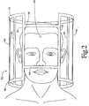
- the local radio frequency coil assembly 40 includes a less-claustrophobic style quadrature coil 42 with an opening 44 over a subject's face.
- an operator interface and control station 50 includes a human-readable display, such as a video monitor 52 , and an operator input means including a keyboard 54 , a mouse 56 , a trackball, light pen, or the like.
- a computer control and reconstruction module 58 includes hardware and software for enabling the operator to select among a plurality of preprogrammed magnetic resonance sequences that are stored in a sequence control memory.
- a sequence controller 60 controls gradient amplifiers 62 and a digital transmitter 70 .
- the gradient amplifiers are connected with the gradient coil assembly 30 for causing the generation of the G x , G y , and G z gradient magnetic fields at appropriate times during the selected gradient sequence.
- the digital transmitter 70 causes a the whole body frequency coil 36 to generate B 1 radio frequency field pulses at times appropriate to the selected sequence.
- the resonance frequency signals are demodulated by a digital receiver 72 and stored in a data memory 74 .
- Data from the memory is reconstructed by a reconstruction or array processor 76 into corresponding volumetric image representations that are stored in corresponding portions of an image memory 78 .
- a video processor 80 under operator control, converts selected portions of the volumetric image representation into slice images, projection images, perspective views, or the like as is conventional in the art for display on the video monitor 52 .
- the coil 42 because it is quadrature, it has outputs for two linear modes, preferably orthogonal modes A and B .
- the orthogonal modes of the coil are processed by a quadrature, hybrid coil-mounted processing circuit 64 which preamplifies, combines, and digitizes the received radio frequency magnetic resonance signals.
- the analog resonance signals can be phase shifted by 90° and combined in analog and their sums digitized for conveyance to the receiver.
- the analog sum can be conveyed directly to the receiver, which receiver demodulates and digitizes the resultant resonance signals.
- the processing circuit 64 provides a two-port feed to 90° offset points 66 and 68 along the circumference of the coil.
- a current flowing through the n-th leg varies as sin(2 ⁇ n/N+ ⁇ ) , where ⁇ is the phase angle which determines the polarization plane of the resulting B 1 radio frequency field.
- the illustrated less-claustrophobic coil construction exhibits a standing wave behavior. Due to the sinusoidal current distributions, its two modes A, B are orthogonal to one another and offer homogeneous B 1 field distributions for uniform transmission and reception.
- the circuit provides asymmetric current distribution with respect to the two feed points, and provides a high degree of B 1 homogeneity in the x, y, and z planes at coil centre. This uniformity at coil centre is achieved without compromising the signal to noise ratio at coil centre.
- the less-claustrophobic insert coil 40 of the preferred embodiment is designed to be converted from a conventional sixteen-leg high-pass birdcage coil without compromising signal to noise and RF homogeneity.
- the conventional coil has eight-fold symmetry while the resultant, less-claustrophobic coil has four-fold symmetry.
- the less-claustrophobic insert coil includes a pair of broken end rings or first and second arcuate conductor segments 90 and 92 , respectively, subtending approximately 292.5° of arc.
- the less-claustrophobic coil may have an endcap in place of one of the discontinuous end rings.
- the pair of broken end rings 90, 92 are connected in parallel by N leg conductors or legs 94 .
- N two anterior legs have been removed to open the viewing area of the patient.
- N 14.
- the segments 96 and 98 are positioned toward the coil centre from the broken end rings 90, 92 such that they are equally-spaced from the remaining sections of the broken end rings.
- each of the pair of broken end rings 90, 92 is interrupted with capacitors C 1 and C 2 .
- the arc segments 96, 98 are interrupted with capacitors C 3 and C 3 ' , respectively, and a tuning capacito r C 4 .
- the tuning capacitor C 4 is placed across the fixed value capacitor C 3 ' in the anterior opening to align and isolate the two principal modes of the coil.
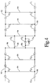
- the circuit diagram of Figure 4 has been broken and laid flat and that the circuit continues to the right with capacitors C 1 .
- the capacitors are sized and tuned such that the coil operates at a selected nuclear magnetic resonance frequency. Alternately, the geometry of the coil can be adjusted to adjust the resonant frequencies. For example, physical dimensions, number of legs, impedance properties of the coil, and the like can be changed.
- the distribution of the legs, the inductance and capacitance values in the different conductors or meshes, and the sinusoidal current distribution are adjusted to maintain similar phase shifts with a comparable birdcage coil without losing the circular polarization and quadrature aspect of the resonator.
- the coil has a diameter and length of 30 cm.
- the two broken end ring segments 96, 98 are spaced 15 cm apart.
- the coil is built with copper foil that is 1.25 cm wide and 0.05 mm thick.
- additional capacitors are placed at 45 degrees with respect to the coupling ports on the coil to tune and isolate the two principal linear modes.
- isolation can be achieved by a remote isolation network or combination of the additional capacitors and network.
- higher order modes can be used for imaging.
- the principal modes can be tuned to the same or different frequencies.
- the less-claustrophobic coil can be used alone for transmit, receive, or transmit and receive purposes.
- the coil can be used with local gradients for very high-resolution or rapid imaging.
- the less-claustrophobic coil 40 has improved the signal to noise ratio at coil centre by approximately 4%. Also, the uniformity in the axial slice in the central axial plane is 89% as compared to 93% for the similar birdcage coil. This difference in uniformity is due to use of a four port feed in the birdcage coil rather than the two port feed of the less-claustrophobic coil. Weighted spin echo images using identical imaging parameters display little or no difference in the overall image quality.
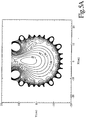
- the less-claustrophobic coil provides satisfactory uniformity of the B1 field in the axial and sagittal planes of the coil, respectively.
- the anterior region of the axial slice has exceptional uniformity which may be advantageously used in imaging this area.
- the signal intensities computed using Biot Savart calculations for unity current at the coil centres for the conventional birdcage coil and the less-claustrophobic coil of Figure 2 are 0.06184 and 0.05825 units, respectively. Thus, there is little reduction (approximately 6%) in the signal intensities at coil centre.
- the signal intensity is further optimized with careful placements of the legs and end ring segments.
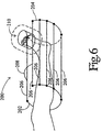
- an alternate embodiment includes an elongated RF coil 200 for use in imaging extremities such as the knee and foot.
- the coil includes a pair of broken end rings 202 , 204 connected in parallel by legs 206 .
- An arcuate cross-segment 208 and toe coil 210 connect two widely-spaced legs of the elongated RF coil.
- the toe coil is at an angle of approximately 10 to 20 degrees with respect to the vertical axis to accommodate most feet in a relaxed position.
- the toe coil preferably, has inner volume to receive the toes of a patient.
- Another embodiment for knee and foot imaging includes a split top design of the elongated RF coil which provides easier patient access and positioning.
- another less-claustrophobic coil has an elliptical shape, an elliptical shape with an end cap, or other geometry to accommodate the anatomy under investigation.
- Alternate coil embodiments have shoulder cutouts to image the head and neck while still maintaining four-fold, two-fold or no-fold symmetry.
- alternate coil embodiments include coils overlapped with another volume or surface coil, i.e., saddle, solenoid, birdcage, dome, etc., for minimal mutual inductance. Careful placement of the legs and the end ring segments, and carefully selecting and distributing capacitance values significantly aids altering the B 1 field distribution without affecting the overall signal to noise ratio.
- the impedance and the corresponding currents are altered to maintain the same voltage drop across elements in the coil.
- the voltage and the impedance are altered to provide the same current distribution along the coil.
- the other impedances in the coil are altered to bring the voltage or the current distributions back to their original state.
- This change in impedance is accomplished, for example, by changing the inductance or the capacitance values or both.
- the principal mode is tuned to the magnetic resonance frequency of the desired dipoles for optimal performance. As a result, compared to their claustrophobic counterparts, less-claustrophobic coils provide optimal image signal to noise and B 1 uniformity while enhancing patient comfort.
- the less-claustrophobic coils are scaled down to image pediatric and premature neonates or other small subjects.
- the coil is connected with a patient support system, such as a gantry. Once the patient is positioned, the coil then slides forward to a preset position on the patient support system. This insures proper and quick positioning before starting a magnetic resonance study.
- the less-claustrophobic coils of the present invention allow use of life support devices, such as ventilation tubes while the patient is inside the magnet bore during a magnetic resonance study. Further, the less-claustrophobic coils or obvious modifications thereof allow use of photic simulation devices, such as strobe lights place directly over the eyes, for brain functional MR imaging experiments. Still further, the less-claustrophobic coils of the present invention allow placement of displays inside the magnet bore for educational or recreational viewing by the patient.
- the techniques expressed here for modifying magnetic resonance RF coils i.e., modifying shape, number of legs, positioning of segments, etc.
- modifying shape, number of legs, positioning of segments, etc. are applicable to other distributed type coils such as volume and surface coil designs.
- saddle coils, solenoid coils, dome-type volume coils and the like can be physically altered so long as appropriate capacitance and inductance values are selected to compensate for phases shifts.
- near optimal performance characteristics are achieved without compromising patient comfort or accessibility.
- either two or a symmetric four-port magnetic (inductive) or electrical (capacitive) coupling are used to match the two linear modes of the coil to 50 ohms.
- the currents in the opening and remainder of the coil may be optimally controlled by careful placement of conductor elements and varying the mesh impedances in and around the opening.
- the coils can be of a high-pass, low-pass, or band-stop configuration, or any combination thereof.
- the less-claustrophobic coil is used in combination with an additional radio-frequency coil.
- the less-claustrophobic coil is tuned to more than one resonance frequency as is the additional coil.
- the less-claustrophobic coil and additional coil are tuned to different resonance frequencies.
- the less-claustrophobic quadrature radio-frequency head coils for nuclear magnetic resonance described above have a number of advantages.
- One advantage is that the coil has a signal-to-noise ratio and homogeneity that is comparable to a conventional coil of similar dimension.
- Another advantage resides in improved patient comfort.
- Another advantage is that coil permits use of life support, diagnostic and other systems during magnetic resonance imaging of the patient. Similarly, the coil permits interventional surgery while the coil is in place on the patient.
- a further advantage is that it permits easy adaptation of other RF coils into less-claustrophobic coils.
- Another advantage resides in additional degrees of freedom in coil design for optimizing the B 1 field profile, and the like.
Landscapes
- Physics & Mathematics (AREA)
- Condensed Matter Physics & Semiconductors (AREA)
- General Physics & Mathematics (AREA)
- Magnetic Resonance Imaging Apparatus (AREA)
Applications Claiming Priority (2)
| Application Number | Priority Date | Filing Date | Title |
|---|---|---|---|
| US08/976,857 US6029082A (en) | 1997-11-24 | 1997-11-24 | Less-claustrophobic, quadrature, radio-frequency head coil for nuclear magnetic resonance |
| US976857 | 1997-11-24 |
Publications (2)
| Publication Number | Publication Date |
|---|---|
| EP0918228A2 true EP0918228A2 (de) | 1999-05-26 |
| EP0918228A3 EP0918228A3 (de) | 2000-04-26 |
Family
ID=25524554
Family Applications (1)
| Application Number | Title | Priority Date | Filing Date |
|---|---|---|---|
| EP98308278A Withdrawn EP0918228A3 (de) | 1997-11-24 | 1998-10-12 | Radiofrequenzspule f r die Magnetresonanz |
Country Status (2)
| Country | Link |
|---|---|
| US (1) | US6029082A (de) |
| EP (1) | EP0918228A3 (de) |
Cited By (2)
| Publication number | Priority date | Publication date | Assignee | Title |
|---|---|---|---|---|
| WO2005050237A1 (en) * | 2003-11-18 | 2005-06-02 | Koninklijke Philips Electronics, N.V. | Hybrid tem/birdcage coil for mri |
| US20190154773A1 (en) * | 2017-11-22 | 2019-05-23 | General Electric Company | Rf coil array for an mri system |
Families Citing this family (59)
| Publication number | Priority date | Publication date | Assignee | Title |
|---|---|---|---|---|
| GB9511101D0 (en) * | 1995-06-01 | 1995-07-26 | British Tech Group | Magnetic coil |
| US6179771B1 (en) * | 1998-04-21 | 2001-01-30 | Siemens Aktiengesellschaft | Coil arrangement for transcranial magnetic stimulation |
| JP3034841B2 (ja) * | 1998-06-05 | 2000-04-17 | ジーイー横河メディカルシステム株式会社 | Mri用コイル、クレードル及びmri装置 |
| US6404199B1 (en) * | 1998-11-25 | 2002-06-11 | Philips Medical Systems (Cleveland), Inc. | Quadrature RF coil for vertical field MRI systems |
| US6198962B1 (en) * | 1998-11-25 | 2001-03-06 | Toshiba America Mri, Inc. | Quadrature detection coil for interventional MRI |
| WO2000072033A2 (en) * | 1999-05-21 | 2000-11-30 | The General Hospital Corporation | Tem resonator for magnetic resonance imaging |
| US7598739B2 (en) * | 1999-05-21 | 2009-10-06 | Regents Of The University Of Minnesota | Radio frequency gradient, shim and parallel imaging coil |
| US6285189B1 (en) * | 1999-09-04 | 2001-09-04 | Varian, Inc. | Millipede coils |
| US6501274B1 (en) * | 1999-10-15 | 2002-12-31 | Nova Medical, Inc. | Magnetic resonance imaging system using coils having paraxially distributed transmission line elements with outer and inner conductors |
| US6313633B1 (en) * | 1999-12-27 | 2001-11-06 | General Electric Company | Magnetic resonance imaging head coil |
| CA2417525A1 (en) * | 2000-07-31 | 2002-02-07 | Regents Of The University Of Minnesota | Open tem resonators for mri |
| US6591128B1 (en) | 2000-11-09 | 2003-07-08 | Koninklijke Philips Electronics, N.V. | MRI RF coil systems having detachable, relocatable, and or interchangeable sections and MRI imaging systems and methods employing the same |
| DE10125233C1 (de) * | 2001-05-22 | 2002-12-12 | Siemens Ag | Empfangsvorrichtung für eine Kernspintomographieanlage |
| US7906966B1 (en) * | 2001-10-05 | 2011-03-15 | Fonar Corporation | Quadrature foot coil antenna for magnetic resonance imaging |
| US7701209B1 (en) | 2001-10-05 | 2010-04-20 | Fonar Corporation | Coils for horizontal field magnetic resonance imaging |
| US20030184294A1 (en) * | 2002-04-01 | 2003-10-02 | Boskamp Eddy Benjamin | Multiple channel, neuro vascular array coil for magnetic resonance imaging |
| US6995561B2 (en) | 2002-04-01 | 2006-02-07 | Ge Medical Systems Global Technology Company, Llc | Multiple channel, microstrip transceiver volume array for magnetic resonance imaging |
| US6825660B2 (en) | 2002-04-26 | 2004-11-30 | Ge Medical Systems Global Technology Company, Llc | Degenerate birdcage resonator for magnetic resonance imaging |
| US6822450B2 (en) | 2002-04-26 | 2004-11-23 | Ge Medical Systems Global Technology Company, Llc | Multiple channel, cardiac array for sensitivity encoding in magnetic resonance imaging |
| US6992486B2 (en) * | 2002-05-16 | 2006-01-31 | Advanced Imaging Research, Inc. | Radio frequency coil for resonance imaging analysis of pediatric patients |
| US6791321B2 (en) * | 2002-06-18 | 2004-09-14 | Koninklijke Philips Electronics N.V. | Birdcage coils for simultaneous acquisition of spatial harmonics |
| US7123012B2 (en) * | 2002-11-29 | 2006-10-17 | Advanced Imaging Research, Inc. | Multiple tuned radio frequency coil for resonance imaging and spectroscopic analysis |
| US7250764B2 (en) * | 2003-09-12 | 2007-07-31 | Ge Medical Systems Global Technology Company, Llc | Shielded dome resonator for MR scanning of a cerebrum |
| US7053617B2 (en) * | 2003-10-01 | 2006-05-30 | General Electric Co. | Integrated electronic RF shielding apparatus for an MRI magnet |
| US8147396B2 (en) * | 2003-11-26 | 2012-04-03 | Advanced Imaging Research, Inc. | Neonate imaging sub-system |
| US6900637B1 (en) * | 2004-03-19 | 2005-05-31 | Igc Medical Advances, Inc. | Phased array coil with center shifted sensitivity |
| US20050264291A1 (en) | 2004-05-07 | 2005-12-01 | Vaughan J T | Multi-current elements for magnetic resonance radio frequency coils |
| US7378846B1 (en) * | 2004-06-29 | 2008-05-27 | Fonar Corporation | Magnetic resonance imaging method and apparatus for scanning a child |
| US8401615B1 (en) | 2004-11-12 | 2013-03-19 | Fonar Corporation | Planar coil flexion fixture for magnetic resonance imaging and use thereof |
| JP2006175058A (ja) * | 2004-12-22 | 2006-07-06 | Ge Medical Systems Global Technology Co Llc | コイルエレメント選択方法および磁気共鳴イメージング装置 |
| US7362101B2 (en) * | 2005-04-27 | 2008-04-22 | The Regents Of The University Of California | Sense optimized MRI RF coil designed with a target field method |
| JP4787033B2 (ja) * | 2006-02-15 | 2011-10-05 | 株式会社日立製作所 | 核磁気共鳴信号用ソレノイドコイル及び核磁気共鳴信号取得装置 |
| US8022705B2 (en) * | 2006-03-09 | 2011-09-20 | Insight Neuroimaging Systems, Llc | Microstrip coil designs for MRI devices |
| DE102006018158A1 (de) * | 2006-04-19 | 2007-10-25 | Siemens Ag | Zylindrische Magnetresonanzantenne |
| JP4844310B2 (ja) * | 2006-09-13 | 2011-12-28 | 株式会社日立製作所 | 高周波コイルおよび磁気共鳴撮像装置 |
| US9386939B1 (en) | 2007-05-10 | 2016-07-12 | Fonar Corporation | Magnetic resonance imaging of the spine to detect scoliosis |
| US20110130660A1 (en) * | 2008-07-30 | 2011-06-02 | Guy Cloutier | System and method for detection, characterization and imaging of heterogeneity using shear wave induced resonance |
| US8710839B2 (en) * | 2008-12-12 | 2014-04-29 | Yale University | O-space imaging: highly efficient parallel imaging using complementary nonlinear encoding gradient fields and receive coil geometries |
| DE102008063629B4 (de) * | 2008-12-18 | 2012-05-24 | Siemens Aktiengesellschaft | Lokalspulenanordnung für Magnetresonanzanwendungen und Patientenliege für eine Magnetresonanzanlage mit integrierten elektrischen Schnittstellen |
| WO2010148095A2 (en) * | 2009-06-16 | 2010-12-23 | Neocoil, Llc | Modular apparatus for magnetic resonance imaging |
| JP5248557B2 (ja) * | 2010-07-29 | 2013-07-31 | ジーイー・メディカル・システムズ・グローバル・テクノロジー・カンパニー・エルエルシー | 磁気共鳴イメージング装置 |
| DE102010033322A1 (de) * | 2010-08-04 | 2012-02-09 | Siemens Aktiengesellschaft | Mechanisch flexible MR Spule mit öffnungsfähigen Leiterstrukturen für insbesondere interventionelle MRT |
| DE102011006157B4 (de) * | 2011-03-25 | 2016-06-16 | Bruker Biospin Ag | Doppelt abgestimmter HF-Resonator |
| US10058267B2 (en) | 2011-04-15 | 2018-08-28 | Neocoil, Llc | Antenna support structure for magnetic resonance imaging |
| DE102011079383A1 (de) * | 2011-07-19 | 2013-01-24 | Siemens Aktiengesellschaft | Magnetresonanzvorrichtung |
| US11141080B1 (en) | 2013-03-13 | 2021-10-12 | Fonar Corporation | Cervical vertebra angle measurement |
| US10656225B2 (en) * | 2016-09-01 | 2020-05-19 | Canon Medical Systems Corporation | Magnetic resonance imaging apparatus |
| WO2018098355A1 (en) | 2016-11-23 | 2018-05-31 | General Electric Company | A conforming posterior radio frequency (rf) coil array for a magnetic resonance imaging (mri) system |
| WO2018098331A1 (en) | 2016-11-23 | 2018-05-31 | General Electric Company | An anterior radio frequency (rf) coil array for a magnetic resonance imaging (mri) system |
| CN206460159U (zh) * | 2017-01-25 | 2017-09-01 | 西门子(深圳)磁共振有限公司 | 非典型线圈的端环端口结构、线圈组件和磁共振成像系统 |
| US10921399B2 (en) * | 2017-11-22 | 2021-02-16 | GE Precision Healthcare LLC | Radio frequency (RF) coil array for a magnetic resonance imaging (MRI) system for use in interventional and surgical procedures |
| US10969447B2 (en) * | 2017-11-22 | 2021-04-06 | General Electric Company | Flexible radio frequency coil array with detachable straps for MR imaging |
| EP3489704A1 (de) * | 2017-11-24 | 2019-05-29 | Sirona Dental Systems GmbH | Lokale mrt-spule für eine dentale mrt-messung |
| EP3709040B1 (de) * | 2019-03-13 | 2025-04-30 | Siemens Healthineers AG | Verfahren zum betrieb einer magnetfeldkamera |
| US11397229B2 (en) | 2019-03-14 | 2022-07-26 | Shanghai United Imaging Healthcare Co., Ltd. | Local coil apparatus for magnetic resonance imaging |
| US11428765B2 (en) * | 2019-11-05 | 2022-08-30 | Quality Electrodynamics, Llc | MRI head coil comprising an open shield |
| US11592504B2 (en) * | 2020-03-26 | 2023-02-28 | Quality Electrodynamics, Llc | MRI coil with a RF shield for radiation or x-ray applications |
| US11408951B2 (en) * | 2020-04-24 | 2022-08-09 | MR CoilTech Limited | Open-face, dual-mode head coil for clinical imaging in ultra-high field MRI scanner |
| WO2025231639A1 (zh) * | 2024-05-08 | 2025-11-13 | 中国科学院深圳先进技术研究院 | 一种磁共振头部功能检测射频线圈 |
Family Cites Families (10)
| Publication number | Priority date | Publication date | Assignee | Title |
|---|---|---|---|---|
| US4692705A (en) * | 1983-12-23 | 1987-09-08 | General Electric Company | Radio frequency field coil for NMR |
| US4769605A (en) * | 1986-11-26 | 1988-09-06 | Kabushiki Kaisha Toshiba | Network to cancel coupling between channels of quadrature antenna coil assembly in a magnetic resonance imaging system |
| US5212450A (en) * | 1990-10-25 | 1993-05-18 | Fox Chase Cancer Center | Radio frequency volume resonator for nuclear magnetic resonance |
| US5315251A (en) * | 1990-12-19 | 1994-05-24 | Toshiba America Mri, Inc. | NMR radio-frequency coil |
| US5277183A (en) * | 1992-06-22 | 1994-01-11 | Medical Advances, Inc. | NMR local coil for foot imaging |
| DE4318134C2 (de) * | 1993-06-01 | 1999-02-11 | Siemens Ag | Zirkular polarisierende Lokalantenne |
| US5619996A (en) * | 1995-03-15 | 1997-04-15 | Medical Advances, Inc. | NMR local coil providing improved lower brain imaging |
| DE19511796C2 (de) * | 1995-03-30 | 1998-10-01 | Siemens Ag | Kopfantenne für Magnetresonanzuntersuchungen |
| US5602479A (en) * | 1995-08-08 | 1997-02-11 | Picker International, Inc. | Quadrature radio frequency coil for magnetic resonance imaging |
| US5664568A (en) * | 1995-08-08 | 1997-09-09 | Picker International, Inc. | Split-top, neck and head vascular array for magnetic resonance imaging |
-
1997
- 1997-11-24 US US08/976,857 patent/US6029082A/en not_active Expired - Fee Related
-
1998
- 1998-10-12 EP EP98308278A patent/EP0918228A3/de not_active Withdrawn
Cited By (3)
| Publication number | Priority date | Publication date | Assignee | Title |
|---|---|---|---|---|
| WO2005050237A1 (en) * | 2003-11-18 | 2005-06-02 | Koninklijke Philips Electronics, N.V. | Hybrid tem/birdcage coil for mri |
| US20190154773A1 (en) * | 2017-11-22 | 2019-05-23 | General Electric Company | Rf coil array for an mri system |
| US10983185B2 (en) * | 2017-11-22 | 2021-04-20 | General Electric Company | RF coil array for an MRI system |
Also Published As
| Publication number | Publication date |
|---|---|
| EP0918228A3 (de) | 2000-04-26 |
| US6029082A (en) | 2000-02-22 |
Similar Documents
| Publication | Publication Date | Title |
|---|---|---|
| US6029082A (en) | Less-claustrophobic, quadrature, radio-frequency head coil for nuclear magnetic resonance | |
| US5543711A (en) | Multiple quadrature volume coils for magnetic resonance imaging | |
| US6396271B1 (en) | Tunable birdcage transmitter coil | |
| US5990681A (en) | Low-cost, snap-in whole-body RF coil with mechanically switchable resonant frequencies | |
| US5602479A (en) | Quadrature radio frequency coil for magnetic resonance imaging | |
| US8125225B2 (en) | Transmit profile control in MRI | |
| US5185576A (en) | Local gradient coil | |
| US5998999A (en) | Volume RF coils with integrated high resolution focus coils for magnetic resonance imaging | |
| US5664568A (en) | Split-top, neck and head vascular array for magnetic resonance imaging | |
| US5050605A (en) | Magnetic resonance imaging antennas with spiral coils and imaging methods employing the same | |
| US6906518B2 (en) | RF coil system for magnetic resonance imaging apparatus | |
| EP1059539B1 (de) | RF-Körperspule für ein offenes System zur Bilderzeugung mittels magnetischer Resonanz | |
| US6591128B1 (en) | MRI RF coil systems having detachable, relocatable, and or interchangeable sections and MRI imaging systems and methods employing the same | |
| US5680047A (en) | Multipl-tuned radio frequency coil for simultaneous magnetic resonance imaging and spectroscopy | |
| US7495443B2 (en) | RF coil system for super high field (SHF) MRI | |
| US7999548B1 (en) | Dual lower extremity MRI coil array with simultaneously independent MRI signal detection from both legs | |
| US5280248A (en) | Biplanar RF coil for magnetic resonance imaging systems | |
| US5689189A (en) | Technique for designing distributed radio frequency coils and distributed radio frequency coils designed thereby | |
| US6650118B2 (en) | RF coil system for an MR apparatus | |
| US6211677B1 (en) | Lung coil for imaging hyper-polarized gas in an MRI scanner | |
| US5646530A (en) | Surface coil for high resolution imaging using a magnetic resonance imaging apparatus | |
| US7391213B2 (en) | Three axis angle invariant RF coil assembly and method and system employing same | |
| US7348778B2 (en) | System and apparatus for a high resolution peripheral vascular coil array | |
| WO2008100546A1 (en) | Transmit profile control in mri | |
| US5933007A (en) | MR device for determining a nuclear magnetization distribution by means of a surface coil system |
Legal Events
| Date | Code | Title | Description |
|---|---|---|---|
| PUAI | Public reference made under article 153(3) epc to a published international application that has entered the european phase |
Free format text: ORIGINAL CODE: 0009012 |
|
| AK | Designated contracting states |
Kind code of ref document: A2 Designated state(s): DE FR NL |
|
| AX | Request for extension of the european patent |
Free format text: AL;LT;LV;MK;RO;SI |
|
| PUAL | Search report despatched |
Free format text: ORIGINAL CODE: 0009013 |
|
| AK | Designated contracting states |
Kind code of ref document: A3 Designated state(s): AT BE CH CY DE DK ES FI FR GB GR IE IT LI LU MC NL PT SE |
|
| AX | Request for extension of the european patent |
Free format text: AL;LT;LV;MK;RO;SI |
|
| 17P | Request for examination filed |
Effective date: 20001018 |
|
| AKX | Designation fees paid |
Free format text: DE FR NL |
|
| RAP1 | Party data changed (applicant data changed or rights of an application transferred) |
Owner name: MARCONI MEDICAL SYSTEMS, INC. |
|
| STAA | Information on the status of an ep patent application or granted ep patent |
Free format text: STATUS: THE APPLICATION HAS BEEN WITHDRAWN |
|
| 18W | Application withdrawn |
Effective date: 20030512 |
|
| RIN1 | Information on inventor provided before grant (corrected) |
Inventor name: ELEK, ROBERT A. Inventor name: LIU, HAIYING Inventor name: SRINIVASAN, RAVI |