EP0916917B1 - Dispositif de protection de releveurs dans un refroidisseur tubulaire rotatif de cimenterie - Google Patents
Dispositif de protection de releveurs dans un refroidisseur tubulaire rotatif de cimenterie Download PDFInfo
- Publication number
- EP0916917B1 EP0916917B1 EP19970203588 EP97203588A EP0916917B1 EP 0916917 B1 EP0916917 B1 EP 0916917B1 EP 19970203588 EP19970203588 EP 19970203588 EP 97203588 A EP97203588 A EP 97203588A EP 0916917 B1 EP0916917 B1 EP 0916917B1
- Authority
- EP
- European Patent Office
- Prior art keywords
- lifters
- cooler
- cap
- lifter
- clinker
- Prior art date
- Legal status (The legal status is an assumption and is not a legal conclusion. Google has not performed a legal analysis and makes no representation as to the accuracy of the status listed.)
- Expired - Lifetime
Links
Images

Classifications
-
- F—MECHANICAL ENGINEERING; LIGHTING; HEATING; WEAPONS; BLASTING
- F27—FURNACES; KILNS; OVENS; RETORTS
- F27D—DETAILS OR ACCESSORIES OF FURNACES, KILNS, OVENS OR RETORTS, IN SO FAR AS THEY ARE OF KINDS OCCURRING IN MORE THAN ONE KIND OF FURNACE
- F27D1/00—Casings; Linings; Walls; Roofs
- F27D1/14—Supports for linings
- F27D1/145—Assembling elements
-
- F—MECHANICAL ENGINEERING; LIGHTING; HEATING; WEAPONS; BLASTING
- F27—FURNACES; KILNS; OVENS; RETORTS
- F27B—FURNACES, KILNS, OVENS OR RETORTS IN GENERAL; OPEN SINTERING OR LIKE APPARATUS
- F27B7/00—Rotary-drum furnaces, i.e. horizontal or slightly inclined
- F27B7/14—Rotary-drum furnaces, i.e. horizontal or slightly inclined with means for agitating or moving the charge
- F27B7/16—Rotary-drum furnaces, i.e. horizontal or slightly inclined with means for agitating or moving the charge the means being fixed relatively to the drum, e.g. composite means
- F27B7/161—Rotary-drum furnaces, i.e. horizontal or slightly inclined with means for agitating or moving the charge the means being fixed relatively to the drum, e.g. composite means the means comprising projections jutting out from the wall
- F27B7/162—Rotary-drum furnaces, i.e. horizontal or slightly inclined with means for agitating or moving the charge the means being fixed relatively to the drum, e.g. composite means the means comprising projections jutting out from the wall the projections consisting of separate lifting elements, e.g. lifting shovels
Definitions
- the present invention relates to a device for protecting lifters in rotary tubular and satellite coolers cement plant, said lifters being in the form of a tunnel with an arc of almost 180 °, thus forming a vault, and designed to be fixed by their base on the face inside of a cylindrical shell constituting the wall of the cooler which is traversed longitudinally by clinker intended to be cooled by air passing through the cooler in the opposite direction to the clinker progression.
- tubular coolers are intended to cool down to a lowest possible temperature, the clinker which has been heated in a clinkerization oven at temperatures of the order of 1450 ° C. Cooling is carried out as the progression progresses axial of the clinker through the cooler thanks to an air circulation against the grain, which makes it possible to recover, at least in part, the clinker heat.
- the cooler is lined with lifters which, during the rotation of the shell, raise the clinker and improve heat exchange with air when the clinker falls at the bottom of the shell.
- lifters of the kind described in the preamble i.e. in the shape of an arc
- Zement-Kalk-Gips No. 6/1992 and document EP-A-0 367 956.
- These are arc-shaped or tunnel whose interior fills when passing to the bottom of the cooler.
- lifters are exposed to very poor working conditions severe. They must not only have good properties refractory and good resistance to wear and abrasion, but also a certain ductility to resist stresses mechanical. However, it is well known that these properties are not compatible with each other and that the choice of material for the lifters must, therefore, constitute a compromise which must necessarily be made at the expense of either of these properties. The result is that the lifters are subject to rapid wear and have, in general, too short a service life.
- the object of the present invention is to provide a device for protection of the lifters which makes it possible to lengthen their duration appreciably on duty.
- the present invention provides a lifter protection device in a tubular cooler cement plant rotary of the kind described in the preamble which is characterized in that it is a hat protection with good wear resistance covering the roof of the lifters.
- the invention thus makes it possible to distribute the tasks and power choose for the hat, on the one hand, and for the reliever, on the other hand, materials whose properties are most suitable for each of the two parts withstands the conditions and stresses well to which it is exposed.
- the hat is advantageously made up of two parts separated longitudinally at the top of the take-up vault. Each of these parts has, for reference, on the entry side from the cooler, a radial flange. These two parts of the hat can be fixed each with a through fixing rod this radial flange and the lifter.
- the lifter generally represented by the reference 10 on the Figure 1 is a tunnel-shaped lifter made up of two sections 12 and 14 in the form of an arc articulated to each other by their apex and intended to be fixed on the inner wall of a cylindrical shell 16 of a tubular cooler using fixing supports 18.
- the base of section 14 which, viewed in the direction of rotation of the cooler, is at the front, is more shorter than the base of the rear section 12, so that the lifter has, seen in developed, a trapezoid shape.
- Each of the two sections 12 and 14 constituting the lifter comprises a full arch 20 provided with external reinforcing ribs 22 which extend radially from the base of each section 12 and 14 to the articulated summit. These ribs give more resistance mechanical lifters 10.
- the present invention provides for styling each lifter 10 of a protective hat generally designated by the reference 30.
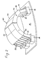
- the cap 30 is preferably made up of two parts 32 and 34 adapted to the two sections 12 and 14 of the lifter which are separated longitudinally at the top of the lifter 10. Both parts 32, 34 have flanges on the inlet side of the cooler radial 36, 38 which hold the cap on the lifters and which protect the lifters from wear by the clinker advancing in the cooler.
- the cap 30 is fixed using rods fixing 40 passing through the flanges 36 and 38 and the ribs 22 to which they can be welded.
- the caps 30 essentially cover the upper part from the arch of the lifters 10, where degradation by heat and by wear is the most important, but can extend to all near the base of the lifters 10.
- the caps 30 are made of a refractory material having good wear resistance, such as refractory steel chrome or even ceramic. When the caps 30 are worn, it it is possible to replace or even recharge them. It is also possible to let the lifters wear out until a stop program. In any event, tests have shown that the protective hats proposed by the present invention allow double the lifespan of lifters.
Landscapes
- Engineering & Computer Science (AREA)
- Mechanical Engineering (AREA)
- General Engineering & Computer Science (AREA)
- Muffle Furnaces And Rotary Kilns (AREA)
- Furnace Housings, Linings, Walls, And Ceilings (AREA)
- Furnace Details (AREA)
- Turbine Rotor Nozzle Sealing (AREA)
Description
- la figure 1 représente une vue en perspective et en éclaté d'un releveur avec un dispositif de protection selon la présente invention et
- la figure 2 représente en perspective un releveur en état de fonctionnement coiffé d'un chapeau de protection selon la présente invention.
Claims (6)
- Dispositif de protection de releveurs dans un refroidisseur tubulaire rotatif de cimenterie, lesdits releveurs (10) étant en forme de tunnel avec un arc de presque 180°, formant ainsi une voûte, et conçus pour être fixés par leur base sur la face intérieure d'une virole cylindrique (16) constituant la paroi du refroidisseur qui est traversé longitudinalement par du clinker destiné à être refroidi par de l'air traversant le refroidisseur dans le sens contraire de la progression du clinker, caractérisé en ce que le dispositif de protection est un chapeau de protection (30) ayant une bonne résistance à l'usure coiffant ladite voûte des releveurs (10).
- Dispositif selon la revendication 1, caractérisé en ce que le chapeau (30) est en deux parties (32, 34) séparées longitudinalement au sommet de la voûte du releveur (10).
- Dispositif selon la revendication 2, caractérisé en ce que chaque partie (32, 34) comporte, du côté de l'entrée du refroidisseur, une bride radiale (36, 38).
- Dispositif selon la revendication 3, caractérisé en ce que les deux parties (32, 34) du chapeau (30) sont fixées, chacune, à l'aide d'une tige de fixation (40) traversant la bride radiale (36, 38) et le releveur (10).
- Dispositif selon l'une quelconque des revendications 1 à 4, caractérisé en ce que le chapeau (30) est en acier au chrome.
- Dispositif selon l'une quelconque des revendications 1 à 4, caractérisé en ce que le chapeau (30) est réalisé en un matériau céramique technique ou composite.
Priority Applications (5)
| Application Number | Priority Date | Filing Date | Title |
|---|---|---|---|
| DE69723268T DE69723268T2 (de) | 1997-11-18 | 1997-11-18 | Schutzeinrichtung für Streuschaufel eines Drehrohkühlers in der Zementindustrie |
| ES97203588T ES2202540T3 (es) | 1997-11-18 | 1997-11-18 | Dispositivo de proteccion de elevadores en un refrigerador tubular rotativo de fabrica de cemento. |
| EP19970203588 EP0916917B1 (fr) | 1997-11-18 | 1997-11-18 | Dispositif de protection de releveurs dans un refroidisseur tubulaire rotatif de cimenterie |
| BR9804559A BR9804559A (pt) | 1997-11-18 | 1998-11-05 | Dispositivo de proteção de levantadores em um resfriador tubular rotativo de cimenteira |
| TR1998/02336A TR199802336A3 (tr) | 1997-11-18 | 1998-11-17 | Çimento imalathanesinin döner borulu sogutucusundaki kaldirma tablalarini koruyucu tertibat |
Applications Claiming Priority (1)
| Application Number | Priority Date | Filing Date | Title |
|---|---|---|---|
| EP19970203588 EP0916917B1 (fr) | 1997-11-18 | 1997-11-18 | Dispositif de protection de releveurs dans un refroidisseur tubulaire rotatif de cimenterie |
Publications (2)
| Publication Number | Publication Date |
|---|---|
| EP0916917A1 EP0916917A1 (fr) | 1999-05-19 |
| EP0916917B1 true EP0916917B1 (fr) | 2003-07-02 |
Family
ID=8228934
Family Applications (1)
| Application Number | Title | Priority Date | Filing Date |
|---|---|---|---|
| EP19970203588 Expired - Lifetime EP0916917B1 (fr) | 1997-11-18 | 1997-11-18 | Dispositif de protection de releveurs dans un refroidisseur tubulaire rotatif de cimenterie |
Country Status (5)
| Country | Link |
|---|---|
| EP (1) | EP0916917B1 (fr) |
| BR (1) | BR9804559A (fr) |
| DE (1) | DE69723268T2 (fr) |
| ES (1) | ES2202540T3 (fr) |
| TR (1) | TR199802336A3 (fr) |
Families Citing this family (1)
| Publication number | Priority date | Publication date | Assignee | Title |
|---|---|---|---|---|
| DE10208248A1 (de) * | 2002-02-26 | 2003-09-04 | Kloeckner Humboldt Wedag | Einbauten für Rohrkühler, Drehrohröfen oder dergleichen |
Family Cites Families (2)
| Publication number | Priority date | Publication date | Assignee | Title |
|---|---|---|---|---|
| DE3119108A1 (de) * | 1981-05-14 | 1982-12-02 | O & K Orenstein & Koppel AG, 4600 Dortmund | "waermetauscher fuer rieselfaehiges gut" |
| DE3837607A1 (de) * | 1988-11-05 | 1990-05-10 | Kloeckner Humboldt Deutz Ag | Einbauten fuer rohrkuehler, drehrohroefen oder dergleichen |
-
1997
- 1997-11-18 DE DE69723268T patent/DE69723268T2/de not_active Expired - Fee Related
- 1997-11-18 ES ES97203588T patent/ES2202540T3/es not_active Expired - Lifetime
- 1997-11-18 EP EP19970203588 patent/EP0916917B1/fr not_active Expired - Lifetime
-
1998
- 1998-11-05 BR BR9804559A patent/BR9804559A/pt not_active IP Right Cessation
- 1998-11-17 TR TR1998/02336A patent/TR199802336A3/tr unknown
Also Published As
| Publication number | Publication date |
|---|---|
| DE69723268T2 (de) | 2004-05-27 |
| EP0916917A1 (fr) | 1999-05-19 |
| TR199802336A2 (xx) | 1999-06-21 |
| BR9804559A (pt) | 2001-03-20 |
| DE69723268D1 (de) | 2003-08-07 |
| ES2202540T3 (es) | 2004-04-01 |
| TR199802336A3 (tr) | 1999-06-21 |
Similar Documents
| Publication | Publication Date | Title |
|---|---|---|
| FR2479901A1 (fr) | Garniture interieure de chambre de combustion pour une turbine a gaz | |
| FR2931719A1 (fr) | Procede de remplacement d'un profil composite. | |
| FR2851787A1 (fr) | Dispositif de protection d'une structure d'entree d'air d'un moteur a reaction | |
| CA2782249C (fr) | Moyeu d'helice a anneau polygonal renforce et turbomachine equipee d'un tel moyeu | |
| FR2479952A1 (fr) | Stucture de guidage et d'etancheite d'injecteur de carburant pour une turbine a gaz | |
| FR2722855A1 (fr) | Volant moteur a deux masses, a refroidissement par air | |
| LU83985A1 (fr) | Plaque de refroidissement | |
| EP0053049A1 (fr) | Dispositif de protection de l'embouchure d'un four rotatif | |
| CA2057779A1 (fr) | Installation d'essais au sol pour reacteur d'aeronef a tuyere orientable | |
| FR2905930A1 (fr) | Generateur de tourbillon en sortie de gaz chauds | |
| EP0916917A1 (fr) | Dispositif de protection de releveurs dans un refroidisseur tubulaire rotatif de cimenterie | |
| FR3078363A1 (fr) | Anneau mobile d'etancheite | |
| CA2853394A1 (fr) | Panneau composite a ecope de prelevement integree | |
| EP0687884B1 (fr) | Manchon anti-arcure | |
| WO2010055217A1 (fr) | Nacelle pour turboreacteur | |
| EP0916916B1 (fr) | Dispositif de fixation de releveurs dans un refroidisseur tubulaire rotatif de cimenterie | |
| FR2507757A1 (fr) | Cuve comportant des supports destines a des pieces internes | |
| EP0332490B1 (fr) | Poche de transport notamment de métaux liquides | |
| FR2537710A1 (fr) | Structure d'entree pour tambours rotatifs pour le traitement thermique de matieres | |
| EP2877762B1 (fr) | Vanne de controle moteur a fonctionnement ameliore | |
| FR2608706A1 (fr) | Systeme de fixation de bagues de friction | |
| EP0015351B1 (fr) | Conduit de liaison entre l'intérieur et l'extérieur d'un four | |
| CA2696229C (fr) | Joint d'etancheite a appui integre | |
| EP3183442B1 (fr) | Conduit d'air pour le refroidissement d'un accessoire de véhicule automobile | |
| EP1767753B1 (fr) | Dispositif de discrétion infrarouge pour un conduit d'échappement d'un moteur de véhicule |
Legal Events
| Date | Code | Title | Description |
|---|---|---|---|
| PUAI | Public reference made under article 153(3) epc to a published international application that has entered the european phase |
Free format text: ORIGINAL CODE: 0009012 |
|
| AK | Designated contracting states |
Kind code of ref document: A1 Designated state(s): BE DE ES FR |
|
| AX | Request for extension of the european patent |
Free format text: AL;LT;LV;MK;RO;SI |
|
| 17P | Request for examination filed |
Effective date: 19990920 |
|
| AKX | Designation fees paid |
Free format text: BE DE ES FR |
|
| GRAH | Despatch of communication of intention to grant a patent |
Free format text: ORIGINAL CODE: EPIDOS IGRA |
|
| GRAH | Despatch of communication of intention to grant a patent |
Free format text: ORIGINAL CODE: EPIDOS IGRA |
|
| GRAA | (expected) grant |
Free format text: ORIGINAL CODE: 0009210 |
|
| AK | Designated contracting states |
Designated state(s): BE DE ES FR |
|
| REF | Corresponds to: |
Ref document number: 69723268 Country of ref document: DE Date of ref document: 20030807 Kind code of ref document: P |
|
| REG | Reference to a national code |
Ref country code: ES Ref legal event code: FG2A Ref document number: 2202540 Country of ref document: ES Kind code of ref document: T3 |
|
| PLBE | No opposition filed within time limit |
Free format text: ORIGINAL CODE: 0009261 |
|
| STAA | Information on the status of an ep patent application or granted ep patent |
Free format text: STATUS: NO OPPOSITION FILED WITHIN TIME LIMIT |
|
| 26N | No opposition filed |
Effective date: 20040405 |
|
| PGFP | Annual fee paid to national office [announced via postgrant information from national office to epo] |
Ref country code: BE Payment date: 20041022 Year of fee payment: 8 |
|
| PGFP | Annual fee paid to national office [announced via postgrant information from national office to epo] |
Ref country code: DE Payment date: 20041026 Year of fee payment: 8 |
|
| PGFP | Annual fee paid to national office [announced via postgrant information from national office to epo] |
Ref country code: ES Payment date: 20041105 Year of fee payment: 8 |
|
| PGFP | Annual fee paid to national office [announced via postgrant information from national office to epo] |
Ref country code: FR Payment date: 20041125 Year of fee payment: 8 |
|
| PG25 | Lapsed in a contracting state [announced via postgrant information from national office to epo] |
Ref country code: ES Free format text: LAPSE BECAUSE OF NON-PAYMENT OF DUE FEES Effective date: 20051119 |
|
| PG25 | Lapsed in a contracting state [announced via postgrant information from national office to epo] |
Ref country code: BE Free format text: LAPSE BECAUSE OF NON-PAYMENT OF DUE FEES Effective date: 20051130 |
|
| PG25 | Lapsed in a contracting state [announced via postgrant information from national office to epo] |
Ref country code: DE Free format text: LAPSE BECAUSE OF NON-PAYMENT OF DUE FEES Effective date: 20060601 |
|
| PG25 | Lapsed in a contracting state [announced via postgrant information from national office to epo] |
Ref country code: FR Free format text: LAPSE BECAUSE OF NON-PAYMENT OF DUE FEES Effective date: 20060731 |
|
| REG | Reference to a national code |
Ref country code: FR Ref legal event code: ST Effective date: 20060731 |
|
| REG | Reference to a national code |
Ref country code: ES Ref legal event code: FD2A Effective date: 20051119 |
|
| BERE | Be: lapsed |
Owner name: *MAGOTTEAUX INTERNATIONAL Effective date: 20051130 |