EP0916561B1 - Fahrzeug zur Fortbewegung auf äusseren gekrümmten Oberflächen - Google Patents
Fahrzeug zur Fortbewegung auf äusseren gekrümmten Oberflächen Download PDFInfo
- Publication number
- EP0916561B1 EP0916561B1 EP98309222A EP98309222A EP0916561B1 EP 0916561 B1 EP0916561 B1 EP 0916561B1 EP 98309222 A EP98309222 A EP 98309222A EP 98309222 A EP98309222 A EP 98309222A EP 0916561 B1 EP0916561 B1 EP 0916561B1
- Authority
- EP
- European Patent Office
- Prior art keywords
- vehicle according
- traversing vehicle
- bodies
- traversing
- vehicle
- Prior art date
- Legal status (The legal status is an assumption and is not a legal conclusion. Google has not performed a legal analysis and makes no representation as to the accuracy of the status listed.)
- Expired - Lifetime
Links
- 125000006850 spacer group Chemical group 0.000 claims description 12
- 239000000463 material Substances 0.000 claims description 9
- 239000002184 metal Substances 0.000 claims description 5
- 230000002093 peripheral effect Effects 0.000 claims description 5
- 229920003052 natural elastomer Polymers 0.000 claims description 2
- 229920001194 natural rubber Polymers 0.000 claims description 2
- 229920003051 synthetic elastomer Polymers 0.000 claims description 2
- 239000005061 synthetic rubber Substances 0.000 claims description 2
- 229920001971 elastomer Polymers 0.000 description 9
- 239000005060 rubber Substances 0.000 description 9
- 238000012544 monitoring process Methods 0.000 description 4
- 229910000906 Bronze Inorganic materials 0.000 description 3
- OAICVXFJPJFONN-UHFFFAOYSA-N Phosphorus Chemical compound [P] OAICVXFJPJFONN-UHFFFAOYSA-N 0.000 description 3
- 229910000831 Steel Inorganic materials 0.000 description 3
- 239000010974 bronze Substances 0.000 description 3
- KUNSUQLRTQLHQQ-UHFFFAOYSA-N copper tin Chemical compound [Cu].[Sn] KUNSUQLRTQLHQQ-UHFFFAOYSA-N 0.000 description 3
- 239000010959 steel Substances 0.000 description 3
- 230000008602 contraction Effects 0.000 description 2
- 238000007689 inspection Methods 0.000 description 2
- XLYOFNOQVPJJNP-UHFFFAOYSA-N water Substances O XLYOFNOQVPJJNP-UHFFFAOYSA-N 0.000 description 2
- 229910000639 Spring steel Inorganic materials 0.000 description 1
- 230000005611 electricity Effects 0.000 description 1
- 239000012530 fluid Substances 0.000 description 1
- 238000003780 insertion Methods 0.000 description 1
- 230000037431 insertion Effects 0.000 description 1
- 238000009434 installation Methods 0.000 description 1
- 238000000034 method Methods 0.000 description 1
- 230000000717 retained effect Effects 0.000 description 1
- 239000010865 sewage Substances 0.000 description 1
Images

Classifications
-
- B—PERFORMING OPERATIONS; TRANSPORTING
- B61—RAILWAYS
- B61B—RAILWAY SYSTEMS; EQUIPMENT THEREFOR NOT OTHERWISE PROVIDED FOR
- B61B3/00—Elevated railway systems with suspended vehicles
- B61B3/02—Elevated railway systems with suspended vehicles with self-propelled vehicles
-
- B—PERFORMING OPERATIONS; TRANSPORTING
- B61—RAILWAYS
- B61B—RAILWAY SYSTEMS; EQUIPMENT THEREFOR NOT OTHERWISE PROVIDED FOR
- B61B12/00—Component parts, details or accessories not provided for in groups B61B7/00 - B61B11/00
-
- B—PERFORMING OPERATIONS; TRANSPORTING
- B61—RAILWAYS
- B61B—RAILWAY SYSTEMS; EQUIPMENT THEREFOR NOT OTHERWISE PROVIDED FOR
- B61B12/00—Component parts, details or accessories not provided for in groups B61B7/00 - B61B11/00
- B61B12/08—Cable lubrication
Definitions
- the present invention is a vehicle devised for traversing external curved surfaces, for example of pipes, electricity cables or bracing cables, for such purposes as monitoring the condition of the surface or applying a treatment to the surface.
- the convex outer surface tends to cause the surface gripping feature of the vehicle to spread, for example bristles to splay outwardly, thereby reducing the gripping, and in turn the potential load-carrying capacity, of the vehicle.
- This problem is of course made more difficult if the surface is of small diameter, for example that of a support cable.
- the surface-traversing vehicle comprises two bodies interconnected by means to move the bodies towards and away from each other, characterised in that each said body is generally hollow and has a plurality of generally parallel, generally flat resilient members extending across the interior of the body, each said resilient member having an aperture within the region of the centre thereof, the apertures within each body being in general alignment.
- the two generally hollow bodies are preferably rotationally symmetrical, externally and/or internally, but may be of other shapes if desired. Preferably they are of generally cylindrical form. Means are provided between the bodies which connect the two bodies together and by which relative movement of the bodies towards and away from each other may be effected. Such means may be electrically operated, for example by an electrical line from a separate source or from a battery, but it is particularly preferred that these interconnecting means take the form of one or more pneumatic cylinders, or less preferably hydraulic cylinders, by which the bodies are moved towards and away from each other in accordance with the direction of flow of the cylinder operating fluid.
- the means interconnecting the two bodies are pneumatic or hydraulic cylinders
- the vehicle of the present invention may comprise just two hollow bodies, additional such bodies may be used, for example in order to increase the working load of instruments or other equipment to be carried by the vehicle or to extend its operating length.
- the vehicle comprises only two hollow bodies, it may be desired to interconnect them in a manner which permits no lateral relative movement, for example pivoting, especially when only surfaces which are linear in the direction of movement of the vehicle are concerned.
- the bodies be flexibly interconnected, in particular to enable the vehicle to traverse non-linear paths, for example having curves or angles.
- each resilient member extending across the interior of each of the bodies form the means by which the bodies grip the surface being traversed.
- the peripheral shape of each resilient member may be generally disc-shaped when the hollow body is correspondingly of circular cross-section.
- the resilient members are of natural or synthetic rubber or other polymeric material.
- Such relatively flexible members of rubber or the like are supported by being interleaved with other members of greater rigidity.
- Such other members may be of a more rigid synthetic polymeric material or of a metal, for example of steel or especially of phosphor bronze.
- the resilient members may themselves be of a resilient metal, for example of a spring steel or of phosphor bronze.
- each generally flat resilient member is formed with a slightly smaller cross-section than that of the convex surface to be monitored,so that the cable or other article having the convex surface may be gripped within the aperture.
- the resilient member is readily distortable by stretching, for example when it is of rubber, then the article may thereby be passed through the aperture.
- the resilient member is of metal, then it is much preferred to provide one or more radial slots, extending outwardly from the aperture, to permit resilient flexing of the member so that it may encircle the article under examination.
- the resilient members are of a rubber or polymeric material and these members are spaced apart by other, more rigid, members of which the central apertures are of slightly larger cross-section than the apertures in the resilient members. Distortion of the resilient members to accommodate the article under examination may then entail the material of the resilient member, in the region of the central aperture, projecting into the aperture of the more rigid member and as a result engaging the convex article more closely.
- the resilient members of rubber or other polymeric material, are supported between spacers with central apertures which taper in one axial direction, thereby allowing the material of the resilient member around its aperture to project into, and frictionally engage, the tapered aperture of the adjacent spacer.
- each hollow body surrounds the convex surface, and advance along it, when the vehicle is in use.
- the article having the surface under examination or treatment must extend through the aligned central apertures in the resilient members.
- the latter end is introduced at one end of the vehicle and passed through the successive central apertures of each hollow body in turn.
- each hollow body may be designed to swing open along a peripheral line, for example a hinge, generally parallel to the length of the body.
- each body may be formed with a peripheral linear slot through which the article under examination may be introduced.
- the cable-traversing vehicle may be dedicated to monitoring that specific cable only and may be left in position on the cable.
- the power for driving the surface-traversing vehicle of the present invention may be self-contained, that is the vehicle may itself carry electrical batteries by which the advancing mechanism is powered, in general it is convenient to provide the necessary power via a pneumatic or hydraulic line. If the distance of operation of the vehicle is significant, or if the power line represents a significant part of the vehicle load, one or more additional hollow bodies may be provided to assist the towing of the power line or an additional traversing vehicle may be employed.
- the operation of the pneumatic cylinders or other driving means may advantageously be effected by means of a suitable controller, in turn programmed to control the various operations of the vehicle.
- a controller may be carried by the vehicle or remote from it, for example operating the vehicle via a radio link.
- the direction of orientation of the grip of the resilient members upon the surface is required to be reversed.
- this may be achieved by the provision of means for at least one of the bodies, or the vehicle overall, to grip the surface so that the movement of the other body in a reverse direction will cause the orientation of the resilient members of that body to be reversed, in the region surrounding the central apertures.
- the vehicle may include means for retracting the backing plate, either bodily or by operation of an iris aperture mechanism.
- additional support may be provided in the form of one or more wheels or runners engaging the curved surface; for example such wheels may be arranged in groups of 2, 3 or 4 wheels, distributed symmetrically about the main axis of the vehicle.
- the surface-traversing vehicle according to the present invention may be used in a wide range of situations in which it is desired to monitor the condition of the convex outer surface of an elongate article or to apply a treatment to such a surface.
- the vehicle may be designed to travel along the exterior of a service conduit, for example to monitor the condition of its surface or of joints or, for example by electromagnetic methods, to monitor the interior of a conduit.
- the vehicle may be used to travel vertically over the length of a chimney.
- the vehicle is further of particular value for monitoring cables, for example electrical supply cables such as suspended overhead cables or bracing cables acting as stays for large structures, including off-shore structures.
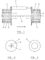
- the surface traversing vehicle illustrated in Figs. 1 to 3 comprises two hollow cylindrical steel bodies 10, 11, axially aligned and connected together by pneumatic cylinders 12. Only one such cylinder is shown in the drawings for the sake of clarity but there are three such pneumatic cylinders interlinking the steel bodies, the cylinders being connected at 120-degree intervals around the periphery of the bodies 10, 11.
- the vehicle surrounds a shaft of which it is intended to monitor the surface and which is indicated in broken line at 13.
- each of the bodies 10, 11 is assembled a sequence of alternating flexible members 14 of phosphor bronze and spacers 15 of synthetic polymeric material. These flexible members and spacers are seen from the front in Figs. 2 and 3 respectively.
- the flexible members 14 are each formed with four radial slots 16, distributed uniformly around a small central aperture 17.
- the diameter of the aperture 17 is slightly less than the diameter of the shaft 13 so that, when the shaft is inserted through this aperture, the parts of the member 14 between the slots 16 must flex slightly to allow passage of the shaft. In this way, the members 14 grip the shaft 13, in a directional manner reflecting the direction of insertion of the shaft. Since the shaft is inserted in the same spatial direction through the two bodies 10, 11, the bodies will both grip the shaft better in a given common direction than in the reverse direction.
- the rearward body (say body 10) grips the shaft and allows the cylinders to push body 11 forward along the shaft, against the lesser resistance in that direction of the members 14 in that body.
- the forward body 11 resists rearward movement along the shaft and the body 10 is thereby pulled forwardly.
- alternate expansion and contraction of the cylinders 12 causes the bodies 10 and 11 to advance in turn along the shaft 13.
- Fig.4 shows a hollow body 18 containing an assemblage of rubber flexible members 19 confined between spacers 20.
- the gripping of the shaft in this case is provided by simple expansion of the central apertures in the rubber members 19 around the shaft.
- the hollow body 21 illustrated in Fig.5 contains thin rubber flexible members 22 supported against rigid discs 23 between rigid spacers 24.
- the discs 23 have central apertures 32 which are slightly larger than the central apertures of the discs 22.
- the apertures 32 taper markedly in one direction as illustrated and thereby allow the rubber surrounding the shaft to enter the apertures 32 and thus to grip the shaft more tightly in that direction than in the opposite direction.
- FIG.6 two flexible members 25, 26 are illustrated gripping a shaft 27.
- Each flexible member is retained against a circular back-plate (28 or 29) by a spacer (30 or 31).
- the member 26 is forced by friction into the central aperture of the plate 29 as shown and thereby grips the shaft 27 tightly.
- the pull on the member 25 allows it to distort away from the shaft and in that way grip the shaft 27 less tightly than does the member 26.
- the member 25 is drawn towards the member 26.
Landscapes
- Engineering & Computer Science (AREA)
- Transportation (AREA)
- Mechanical Engineering (AREA)
- Springs (AREA)
- Vehicle Interior And Exterior Ornaments, Soundproofing, And Insulation (AREA)
- Rear-View Mirror Devices That Are Mounted On The Exterior Of The Vehicle (AREA)
- Investigating Materials By The Use Of Optical Means Adapted For Particular Applications (AREA)
Claims (17)
- Ein sich auf einer Oberfläche bewegendes Fahrzeug, welches zwei Körper (10, 11; 18; 21; 28, 29) umfasst, die miteinander über Mittel (12) verbunden sind, um die Körper zueinander und voneinander weg zu bewegen, dadurch gekennzeichnet, dass jeder der Körper im Allgemeinen hohl ist und eine Vielzahl von im Allgemeinen parallelen, im Allgemeinen flachen elastischen Elementen (14; 19; 22; 25, 26) aufweist, die sich quer durch das Innere des Körpers erstrecken, so dass jedes der elastischen Elemente einen Öffnung in der zentralen Zone desselben hat und dass die Öffnungen innerhalb jedes Körpers im Allgemeinen ausgerichtet sind.
- Ein sich auf einer Oberfläche bewegendes Fahrzeug nach Anspruch 1, dadurch gekennzeichnet, dass die im Allgemeinen hohlen Körper rotationssymmetrisch sind.
- Ein sich auf einer Oberfläche bewegendes Fahrzeug nach einem der vorherigen Ansprüche, dadurch gekennzeichnet, dass die verbindenden Mittel eine oder mehrere pneumatische oder hydraulische Zylinder (12) umfassen.
- Ein sich auf einer Oberfläche bewegendes Fahrzeug nach Anspruch 3, gekennzeichnet durch mindestens drei solcher Zylinder (12), die symmetrisch um die Achse der Körper angeordnet sind.
- Ein sich auf einer Oberfläche bewegendes Fahrzeug nach einem der vorherigen Ansprüche, dadurch gekennzeichnet, dass die im Allgemeinen hohlen Körper flexibel miteinander verbunden sind.
- Ein sich auf einer Oberfläche bewegendes Fahrzeug nach einem der vorherigen Ansprüche, dadurch gekennzeichnet, dass die im Allgemeinen flachen elastischen Elemente (19; 22; 25, 26) aus natürlichem oder synthetischem Gummi oder einem anderen polymeren Material sind.
- Ein sich auf einer Oberfläche bewegendes Fahrzeug nach Anspruch 6, dadurch gekennzeichnet, dass die elastischen Elemente (22; 25, 26) sich mit weiteren Elementen (23, 24; 28, 29) mit größerer Steifigkeit überlappen.
- Ein sich auf einer Oberfläche bewegendes Fahrzeug nach einem der Ansprüche 1 bis 5, dadurch gekennzeichnet, dass die im Allgemeinen flachen elastischen Elemente (14) aus einem elastischen Metall sind.
- Ein sich auf einer Oberfläche bewegendes Fahrzeug nach Anspruch 8, dadurch gekennzeichnet, dass jedes der elastischen Metallelemente (14) eine oder mehrere radiale Schlitze (16) aufweist, die sich von seiner Öffnung nach Außen erstrecken.
- Ein sich auf einer Oberfläche bewegendes Fahrzeug nach Anspruch 7, dadurch gekennzeichnet, dass die zentralen Öffnungen der Elemente (23; 28, 29) von größerer Steifigkeit einen etwas größeren Querschnitt aufweisen als die Öffnungen der elastischen Elemente (22; 25, 26).
- Ein sich auf einer Oberfläche bewegendes Fahrzeug nach Anspruch 7, dadurch gekennzeichnet, dass die elastischen Elemente (22) zwischen Zwischenstücken (23) gestützt werden, welche zentrale Öffnungen (32) aufweisen, die sich in einer axialen Richtung verjüngen.
- Ein sich auf einer Oberfläche bewegendes Fahrzeug nach einem der vorherigen Ansprüche, dadurch gekennzeichnet, dass jeder der im Allgemeinen hohlen Körper frei entlang einer Umfangslinie schwingen kann.
- Ein sich auf einer Oberfläche bewegendes Fahrzeug nach einem der Ansprüche 1 bis 11, dadurch gekennzeichnet, dass jeder der im Allgemeinen hohlen Körper mit einem peripheren linearen Schlitz versehen ist.
- Ein sich auf einer Oberfläche bewegendes Fahrzeug nach einem der vorherigen Ansprüche, dadurch gekennzeichnet, dass es eine oder mehrere zusätzliche der im Allgemeinen hohlen Körper umfasst, um das Schleppen einer Leitung zu begleiten, welche die Leistung für das Fahrzeug bereitstellt.
- Ein sich auf einer Oberfläche bewegendes Fahrzeug nach einem der vorherigen Ansprüche, dadurch gekennzeichnet, dass weiter eine Steuerung vorgesehen ist, um den Einsatz der Mittel (12) zu steuern, um die Körper zueinander oder voneinander weg zu bewegen.
- Ein sich auf einer Oberfläche bewegendes Fahrzeug nach einem der vorherigen Ansprüche, dadurch gekennzeichnet, dass weitere Mittel vorgesehen sind, um mindestens einen der im Allgemeinen hohlen Körper (10, 11; 18; 21; 28, 29) in die Lage zu versetzen, eine Oberfläche abzugreifen, über die sich das Fahrzeug bewegt.
- Ein sich auf einer Oberfläche bewegendes Fahrzeug nach einem der vorherigen Ansprüche gekennzeichnet durch zusätzlichen Halt in Form eines oder mehrerer Räder, welche in die Oberfläche eingreifen.
Applications Claiming Priority (2)
| Application Number | Priority Date | Filing Date | Title |
|---|---|---|---|
| GB9723779 | 1997-11-12 | ||
| GBGB9723779.6A GB9723779D0 (en) | 1997-11-12 | 1997-11-12 | Vehicle for traversing external curved surfaces |
Publications (2)
| Publication Number | Publication Date |
|---|---|
| EP0916561A1 EP0916561A1 (de) | 1999-05-19 |
| EP0916561B1 true EP0916561B1 (de) | 2005-03-30 |
Family
ID=10821887
Family Applications (1)
| Application Number | Title | Priority Date | Filing Date |
|---|---|---|---|
| EP98309222A Expired - Lifetime EP0916561B1 (de) | 1997-11-12 | 1998-11-11 | Fahrzeug zur Fortbewegung auf äusseren gekrümmten Oberflächen |
Country Status (6)
| Country | Link |
|---|---|
| US (1) | US6164397A (de) |
| EP (1) | EP0916561B1 (de) |
| AT (1) | ATE292035T1 (de) |
| DE (1) | DE69829538D1 (de) |
| DK (1) | DK0916561T3 (de) |
| GB (2) | GB9723779D0 (de) |
Families Citing this family (6)
| Publication number | Priority date | Publication date | Assignee | Title |
|---|---|---|---|---|
| US6722442B2 (en) | 1996-08-15 | 2004-04-20 | Weatherford/Lamb, Inc. | Subsurface apparatus |
| GB9617115D0 (en) | 1996-08-15 | 1996-09-25 | Astec Dev Ltd | Pipeline traction system |
| US6488267B1 (en) * | 2000-09-12 | 2002-12-03 | The United States Of America As Represented By The Secretary Of The Army | Apparatus for lifting or pulling a load |
| GB0028619D0 (en) | 2000-11-24 | 2001-01-10 | Weatherford Lamb | Traction apparatus |
| GB2401130B (en) | 2003-04-30 | 2006-11-01 | Weatherford Lamb | A traction apparatus |
| CN103224171B (zh) * | 2013-05-02 | 2015-05-27 | 武汉理工大学 | 一种具有摄像摄影功能的尺蠖式钢丝绳爬行装置 |
Family Cites Families (11)
| Publication number | Priority date | Publication date | Assignee | Title |
|---|---|---|---|---|
| DE278892C (de) * | ||||
| CH316318A (de) * | 1955-09-24 | 1956-09-30 | Hartmann Walter | Drahtseilreinigungsapparat |
| US4223753A (en) * | 1977-12-19 | 1980-09-23 | Bradbury Harold M | Omni-directional transport device |
| US4591390A (en) * | 1981-03-25 | 1986-05-27 | Shell Internationale Research Maatschappij B. V. | Cable cleaning system |
| SU1404693A1 (ru) * | 1984-04-24 | 1988-06-23 | Управление "Спецшахтомонтаж" Производственного Объединения По Добыче Угля "Карагандауголь" | Гидравлический шаговый привод |
| US4615509A (en) * | 1985-10-23 | 1986-10-07 | Cibeles International Inc. | Continuous operation linear hydraulic winch |
| US4919223A (en) * | 1988-01-15 | 1990-04-24 | Shawn E. Egger | Apparatus for remotely controlled movement through tubular conduit |
| DE3937928A1 (de) * | 1989-11-15 | 1991-05-16 | Asea Brown Boveri | Reinigungsgeraet zur reinigung eines rundprofiles, insbesondere eines seiles |
| DE4302731C1 (de) * | 1993-02-01 | 1994-07-14 | Siemens Ag | Im Innern eines Rohres selbsttätig fortbewegbares Transportmittel |
| US5542496A (en) * | 1994-12-15 | 1996-08-06 | St. Denis; Carroll R. | Robotic centering device |
| GB9519368D0 (en) * | 1995-09-22 | 1995-11-22 | Univ Durham | Conduit traversing vehicle |
-
1997
- 1997-11-12 GB GBGB9723779.6A patent/GB9723779D0/en not_active Ceased
-
1998
- 1998-11-10 US US09/190,045 patent/US6164397A/en not_active Expired - Fee Related
- 1998-11-11 EP EP98309222A patent/EP0916561B1/de not_active Expired - Lifetime
- 1998-11-11 GB GB9824635A patent/GB2331347B/en not_active Expired - Fee Related
- 1998-11-11 DK DK98309222T patent/DK0916561T3/da active
- 1998-11-11 AT AT98309222T patent/ATE292035T1/de not_active IP Right Cessation
- 1998-11-11 DE DE69829538T patent/DE69829538D1/de not_active Expired - Lifetime
Also Published As
| Publication number | Publication date |
|---|---|
| ATE292035T1 (de) | 2005-04-15 |
| GB9723779D0 (en) | 1998-01-07 |
| EP0916561A1 (de) | 1999-05-19 |
| US6164397A (en) | 2000-12-26 |
| GB2331347B (en) | 2002-06-05 |
| GB9824635D0 (en) | 1999-01-06 |
| DE69829538D1 (de) | 2005-05-04 |
| GB2331347A (en) | 1999-05-19 |
| DK0916561T3 (da) | 2005-06-06 |
Similar Documents
| Publication | Publication Date | Title |
|---|---|---|
| KR100488059B1 (ko) | 표면횡행차 | |
| AU740870B2 (en) | Surface-traversing vehicle | |
| EP0017616B1 (de) | Verfahren und Vorrichtung für die Verlegung und Befestigung schwerer elektrischer Kabel | |
| US3060972A (en) | Flexible tube structures | |
| US5308026A (en) | Midline cable clamp construction | |
| US6164397A (en) | Vehicle for traversing external curved surfaces | |
| US20060110219A1 (en) | Pipe guide adapter | |
| CN110165606B (zh) | 一种便于线缆装夹的线缆穿管用滑车 | |
| CN110165605B (zh) | 适用于不同管径线缆穿管的牵引滑车 | |
| JP3396760B2 (ja) | 高密度多孔スペーサ | |
| CN110212461B (zh) | 一种自驱动线缆穿管用滑车 | |
| CN110190561B (zh) | 一种适用于线缆弯管敷设用滑车 | |
| JPH02161095A (ja) | 推進工法用推進装置 | |
| CN218449279U (zh) | 一种便于快速穿线的耐外压mpp电力管 | |
| SU1644277A1 (ru) | Устройство дл креплени кабел в трубопроводе | |
| JPS5942486Y2 (ja) | エアクランプ装置 | |
| JPS6333159Y2 (de) | ||
| WO2024047105A1 (en) | A kit of parts for clamping a pole | |
| JPH04110178U (ja) | 管路清掃具 | |
| JPS6321133Y2 (de) | ||
| JPH07993B2 (ja) | 推進工法における埋設管の支持装置 | |
| JPH05302689A (ja) | 管体接続装置及び管体接続方法 | |
| MXPA00007012A (en) | Surface-traversing vehicle | |
| GB2038403A (en) | Adjustable Clamp for Fastening Around a Tubular or Bar-like Object | |
| JPS6259797A (ja) | 地中管体の推進方法 |
Legal Events
| Date | Code | Title | Description |
|---|---|---|---|
| PUAI | Public reference made under article 153(3) epc to a published international application that has entered the european phase |
Free format text: ORIGINAL CODE: 0009012 |
|
| AK | Designated contracting states |
Kind code of ref document: A1 Designated state(s): AT BE CH DE DK ES FI FR GB GR IE IT LI LU MC NL PT SE |
|
| AX | Request for extension of the european patent |
Free format text: AL;LT;LV;MK;RO;SI |
|
| 17P | Request for examination filed |
Effective date: 19991117 |
|
| AKX | Designation fees paid |
Free format text: AT BE CH DE DK ES FI FR GB GR IE IT LI LU MC NL PT SE |
|
| GRAG | Despatch of communication of intention to grant |
Free format text: ORIGINAL CODE: EPIDOS AGRA |
|
| 17Q | First examination report despatched |
Effective date: 20011210 |
|
| GRAG | Despatch of communication of intention to grant |
Free format text: ORIGINAL CODE: EPIDOS AGRA |
|
| RBV | Designated contracting states (corrected) |
Designated state(s): AT BE CH DE DK ES FI FR GR IE IT LI LU MC NL PT SE |
|
| GRAP | Despatch of communication of intention to grant a patent |
Free format text: ORIGINAL CODE: EPIDOSNIGR1 |
|
| GRAU | Approval following communication of intention to grant |
Free format text: ORIGINAL CODE: EPIDOSNAGR4 |
|
| GRAS | Grant fee paid |
Free format text: ORIGINAL CODE: EPIDOSNIGR3 |
|
| GRAA | (expected) grant |
Free format text: ORIGINAL CODE: 0009210 |
|
| AK | Designated contracting states |
Kind code of ref document: B1 Designated state(s): AT BE CH DE DK ES FI FR GR IE IT LI LU MC NL PT SE |
|
| PG25 | Lapsed in a contracting state [announced via postgrant information from national office to epo] |
Ref country code: NL Free format text: LAPSE BECAUSE OF FAILURE TO SUBMIT A TRANSLATION OF THE DESCRIPTION OR TO PAY THE FEE WITHIN THE PRESCRIBED TIME-LIMIT Effective date: 20050330 Ref country code: LI Free format text: LAPSE BECAUSE OF FAILURE TO SUBMIT A TRANSLATION OF THE DESCRIPTION OR TO PAY THE FEE WITHIN THE PRESCRIBED TIME-LIMIT Effective date: 20050330 Ref country code: IT Free format text: LAPSE BECAUSE OF FAILURE TO SUBMIT A TRANSLATION OF THE DESCRIPTION OR TO PAY THE FEE WITHIN THE PRESCRIBED TIME-LIMIT;WARNING: LAPSES OF ITALIAN PATENTS WITH EFFECTIVE DATE BEFORE 2007 MAY HAVE OCCURRED AT ANY TIME BEFORE 2007. THE CORRECT EFFECTIVE DATE MAY BE DIFFERENT FROM THE ONE RECORDED. Effective date: 20050330 Ref country code: FI Free format text: LAPSE BECAUSE OF FAILURE TO SUBMIT A TRANSLATION OF THE DESCRIPTION OR TO PAY THE FEE WITHIN THE PRESCRIBED TIME-LIMIT Effective date: 20050330 Ref country code: CH Free format text: LAPSE BECAUSE OF FAILURE TO SUBMIT A TRANSLATION OF THE DESCRIPTION OR TO PAY THE FEE WITHIN THE PRESCRIBED TIME-LIMIT Effective date: 20050330 Ref country code: BE Free format text: LAPSE BECAUSE OF FAILURE TO SUBMIT A TRANSLATION OF THE DESCRIPTION OR TO PAY THE FEE WITHIN THE PRESCRIBED TIME-LIMIT Effective date: 20050330 Ref country code: AT Free format text: LAPSE BECAUSE OF FAILURE TO SUBMIT A TRANSLATION OF THE DESCRIPTION OR TO PAY THE FEE WITHIN THE PRESCRIBED TIME-LIMIT Effective date: 20050330 |
|
| REG | Reference to a national code |
Ref country code: CH Ref legal event code: EP |
|
| REF | Corresponds to: |
Ref document number: 69829538 Country of ref document: DE Date of ref document: 20050504 Kind code of ref document: P |
|
| REG | Reference to a national code |
Ref country code: IE Ref legal event code: FG4D |
|
| REG | Reference to a national code |
Ref country code: DK Ref legal event code: T3 |
|
| PG25 | Lapsed in a contracting state [announced via postgrant information from national office to epo] |
Ref country code: GR Free format text: LAPSE BECAUSE OF FAILURE TO SUBMIT A TRANSLATION OF THE DESCRIPTION OR TO PAY THE FEE WITHIN THE PRESCRIBED TIME-LIMIT Effective date: 20050630 |
|
| PG25 | Lapsed in a contracting state [announced via postgrant information from national office to epo] |
Ref country code: DE Free format text: LAPSE BECAUSE OF FAILURE TO SUBMIT A TRANSLATION OF THE DESCRIPTION OR TO PAY THE FEE WITHIN THE PRESCRIBED TIME-LIMIT Effective date: 20050701 |
|
| PG25 | Lapsed in a contracting state [announced via postgrant information from national office to epo] |
Ref country code: ES Free format text: LAPSE BECAUSE OF FAILURE TO SUBMIT A TRANSLATION OF THE DESCRIPTION OR TO PAY THE FEE WITHIN THE PRESCRIBED TIME-LIMIT Effective date: 20050711 |
|
| PG25 | Lapsed in a contracting state [announced via postgrant information from national office to epo] |
Ref country code: PT Free format text: LAPSE BECAUSE OF FAILURE TO SUBMIT A TRANSLATION OF THE DESCRIPTION OR TO PAY THE FEE WITHIN THE PRESCRIBED TIME-LIMIT Effective date: 20050907 |
|
| REG | Reference to a national code |
Ref country code: CH Ref legal event code: PL |
|
| NLV1 | Nl: lapsed or annulled due to failure to fulfill the requirements of art. 29p and 29m of the patents act | ||
| PG25 | Lapsed in a contracting state [announced via postgrant information from national office to epo] |
Ref country code: IE Free format text: LAPSE BECAUSE OF NON-PAYMENT OF DUE FEES Effective date: 20051111 |
|
| PG25 | Lapsed in a contracting state [announced via postgrant information from national office to epo] |
Ref country code: MC Free format text: LAPSE BECAUSE OF NON-PAYMENT OF DUE FEES Effective date: 20051130 Ref country code: LU Free format text: LAPSE BECAUSE OF NON-PAYMENT OF DUE FEES Effective date: 20051130 Ref country code: DK Free format text: LAPSE BECAUSE OF NON-PAYMENT OF DUE FEES Effective date: 20051130 |
|
| PLBE | No opposition filed within time limit |
Free format text: ORIGINAL CODE: 0009261 |
|
| STAA | Information on the status of an ep patent application or granted ep patent |
Free format text: STATUS: NO OPPOSITION FILED WITHIN TIME LIMIT |
|
| 26N | No opposition filed |
Effective date: 20060102 |
|
| EN | Fr: translation not filed | ||
| REG | Reference to a national code |
Ref country code: DK Ref legal event code: EBP |
|
| REG | Reference to a national code |
Ref country code: IE Ref legal event code: MM4A |
|
| PG25 | Lapsed in a contracting state [announced via postgrant information from national office to epo] |
Ref country code: SE Free format text: LAPSE BECAUSE OF FAILURE TO SUBMIT A TRANSLATION OF THE DESCRIPTION OR TO PAY THE FEE WITHIN THE PRESCRIBED TIME-LIMIT Effective date: 20050630 |
|
| PG25 | Lapsed in a contracting state [announced via postgrant information from national office to epo] |
Ref country code: FR Free format text: LAPSE BECAUSE OF NON-PAYMENT OF DUE FEES Effective date: 20051130 |
|
| PG25 | Lapsed in a contracting state [announced via postgrant information from national office to epo] |
Ref country code: FR Free format text: LAPSE BECAUSE OF NON-PAYMENT OF DUE FEES Effective date: 20050330 |