EP0915406B1 - Verfahren zur Überwachung des Versorgungssystems einer Gasturbine mit Mehrbrennersystem sowie Vorrichtung zur Durchführung des Verfahrens - Google Patents
Verfahren zur Überwachung des Versorgungssystems einer Gasturbine mit Mehrbrennersystem sowie Vorrichtung zur Durchführung des Verfahrens Download PDFInfo
- Publication number
- EP0915406B1 EP0915406B1 EP97810845A EP97810845A EP0915406B1 EP 0915406 B1 EP0915406 B1 EP 0915406B1 EP 97810845 A EP97810845 A EP 97810845A EP 97810845 A EP97810845 A EP 97810845A EP 0915406 B1 EP0915406 B1 EP 0915406B1
- Authority
- EP
- European Patent Office
- Prior art keywords
- distribution system
- fuel
- pressure
- burners
- water
- Prior art date
- Legal status (The legal status is an assumption and is not a legal conclusion. Google has not performed a legal analysis and makes no representation as to the accuracy of the status listed.)
- Expired - Lifetime
Links
Images

Classifications
-
- G—PHYSICS
- G05—CONTROLLING; REGULATING
- G05B—CONTROL OR REGULATING SYSTEMS IN GENERAL; FUNCTIONAL ELEMENTS OF SUCH SYSTEMS; MONITORING OR TESTING ARRANGEMENTS FOR SUCH SYSTEMS OR ELEMENTS
- G05B23/00—Testing or monitoring of control systems or parts thereof
- G05B23/02—Electric testing or monitoring
- G05B23/0205—Electric testing or monitoring by means of a monitoring system capable of detecting and responding to faults
- G05B23/0218—Electric testing or monitoring by means of a monitoring system capable of detecting and responding to faults characterised by the fault detection method dealing with either existing or incipient faults
- G05B23/0224—Process history based detection method, e.g. whereby history implies the availability of large amounts of data
- G05B23/0227—Qualitative history assessment, whereby the type of data acted upon, e.g. waveforms, images or patterns, is not relevant, e.g. rule based assessment; if-then decisions
- G05B23/0235—Qualitative history assessment, whereby the type of data acted upon, e.g. waveforms, images or patterns, is not relevant, e.g. rule based assessment; if-then decisions based on a comparison with predetermined threshold or range, e.g. "classical methods", carried out during normal operation; threshold adaptation or choice; when or how to compare with the threshold
-
- F—MECHANICAL ENGINEERING; LIGHTING; HEATING; WEAPONS; BLASTING
- F02—COMBUSTION ENGINES; HOT-GAS OR COMBUSTION-PRODUCT ENGINE PLANTS
- F02C—GAS-TURBINE PLANTS; AIR INTAKES FOR JET-PROPULSION PLANTS; CONTROLLING FUEL SUPPLY IN AIR-BREATHING JET-PROPULSION PLANTS
- F02C3/00—Gas-turbine plants characterised by the use of combustion products as the working fluid
- F02C3/20—Gas-turbine plants characterised by the use of combustion products as the working fluid using a special fuel, oxidant, or dilution fluid to generate the combustion products
- F02C3/30—Adding water, steam or other fluids for influencing combustion, e.g. to obtain cleaner exhaust gases
-
- F—MECHANICAL ENGINEERING; LIGHTING; HEATING; WEAPONS; BLASTING
- F02—COMBUSTION ENGINES; HOT-GAS OR COMBUSTION-PRODUCT ENGINE PLANTS
- F02C—GAS-TURBINE PLANTS; AIR INTAKES FOR JET-PROPULSION PLANTS; CONTROLLING FUEL SUPPLY IN AIR-BREATHING JET-PROPULSION PLANTS
- F02C7/00—Features, components parts, details or accessories, not provided for in, or of interest apart form groups F02C1/00 - F02C6/00; Air intakes for jet-propulsion plants
- F02C7/22—Fuel supply systems
- F02C7/228—Dividing fuel between various burners
-
- F—MECHANICAL ENGINEERING; LIGHTING; HEATING; WEAPONS; BLASTING
- F23—COMBUSTION APPARATUS; COMBUSTION PROCESSES
- F23R—GENERATING COMBUSTION PRODUCTS OF HIGH PRESSURE OR HIGH VELOCITY, e.g. GAS-TURBINE COMBUSTION CHAMBERS
- F23R3/00—Continuous combustion chambers using liquid or gaseous fuel
- F23R3/28—Continuous combustion chambers using liquid or gaseous fuel characterised by the fuel supply
- F23R3/36—Supply of different fuels
Definitions
- the present invention relates to the field of Gas turbines. It relates to a method for monitoring the Supply system of a gas turbine with a multi-burner system, which supply system comprises at least one distribution system, via which one for the operation of the multi-burner system required medium under pressure on a plurality of in a combustion chamber opening individual burners is distributed.
- the invention further relates to a device for performing of the method comprising a plurality of in one Combustion chamber opening burners, which have a fuel distribution system with a pressurized liquid Fuel are supplied.
- the task is in a method of the aforementioned Kind of solved in that during the operation of the gas turbine continuously the pressure loss in the at least one distribution system it is measured that the measured pressure drop with a characteristic for the respective operating state of the gas turbine Setpoint is compared and that a message is reimbursed if the measured pressure loss from the associated Setpoint deviates by a predetermined value.
- any load condition e.g. a clearly defined Fuel pressure loss or required fuel pressure exist. If there are now irregularities in the fuel distribution system, so the actually measured fuel pressures give way from the theoretical curve. This fact makes use of the method according to the invention.
- a first preferred embodiment of the method according to the The invention is characterized in that for measuring the Pressure loss in the at least one distribution system Pressure at the inlet of the distribution system and in the combustion chamber measured and the pressure difference from the two pressure values is formed that the at least one distribution system distributing medium via a pump and a downstream of the pump Control valve is supplied, and that for determination the pressure in the distribution system the pressure at the outlet of the Control valve is measured.
- the choice of measuring locations will in a simple way the pressure drop (pressure loss) over the entire distribution system is measured without being constantly Make the changing position of the control valve falsely noticeable can.
- the device according to the invention for carrying out the method comprising a plurality of opening into a combustion chamber Burners with a fuel distribution system a pressurized liquid fuel become. It is characterized in that both on the fuel distribution system as well as on the combustion chamber Pressure sensor is arranged, and that the pressure sensor on a common monitoring unit are connected.
- a preferred embodiment of the device according to the invention is characterized in that the burners in burner groups are summarized that each burner group one assigned their own fuel distribution system or water distribution system is, and that in each fuel distribution system or Water distribution system for monitoring a pressure sensor arranged and is connected to the monitoring unit.
- the Supply system 10 supplies a plurality of burners or Fuel lances 12, 13 and 14 that form a burner group 11 are summarized. Other burners or burner groups are usually present, in Fig. 1 the clarity for the sake of being omitted.
- the supply system 10 includes a fuel distribution system 15 and a water distribution system 24.
- the two distribution systems 15 and 24 are for the Burner group 11 is provided.
- the others (not shown) Burner groups are identified by similar (not shown) Distribution systems supplied.
- the fuel distribution system 15 is powered by a fuel pump 16, a subsequent quick-closing valve 17 and a control valve 18 fuel (usually oil) fed under pressure.
- the fuel is delivered through the fuel distribution system 15 distributed to the individual burners 12, .., 14, with each Burner 12, .., 14 a first section valve 123, 133, 143 is arranged, which is a control of the fuel supply made possible for each burner individually.
- a ventilation valve for maintenance purposes 21 and a drain valve 22 are provided on Fuel distribution system 15 .
- the burners 12, .., 14 can be supplied with fuel gas via a fuel gas feed line 40.
- the water distribution system 24 becomes analogous to the fuel distribution system 15 via a water pump 25, a subsequent one Quick-closing valve 26 and a control valve 27 water (or Steam) supplied under pressure.
- the water is through the Water distribution system 24 to the individual burners 12, .., 14 distributed, with a second section valve on each burner 12, .., 14 121, 131, 141 is arranged, which one Control of the water supply for each burner individually.
- Between the quick-closing valve 26 and the control valve 27 responsible for the water distribution system 24 further lines 30 go to parallel water distribution systems and burner groups. All water distribution systems together are also protected by a common relief valve 28.
- Both the fuel in the fuel distribution system 15 as well the water in the water distribution system 24 suffers from the flow resistance a pressure loss in the system, which for the respective State of the system is characteristic.
- the pressure loss is the pressure difference between the pressure at Entry of the respective distribution system and at the exit of the Burner 12, .., 14 or in the combustion chamber (not shown), into which the burners open, and those with compressed combustion air charged from the compressor part of the gas turbine is.
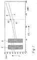
- the pressure drop is now according to the invention measured and monitored. Deviations from a reference value (Setpoint) or a reference value curve (setpoint curve A or Setpoint A1 in Fig. 2) are detected and for early Analysis of errors in the supply system or for early preparation of inspection and service work used.
- a pressure sensor 20 or 29 is arranged, respectively continuously (e.g. periodically) the inlet pressure in the distribution system measures and the measured values (over the dotted lines Lines) to a central monitoring unit (32) delivers.
- the differences are now 32 in difference formers 33 and 34, respectively from the pressure sensors 20 and 31 and 29 and 31 measured pressure values are formed and in each case to subsequent ones Comparators 35 and 36 forwarded.
- the procedure is as follows: Combustion chamber driving concept like this. installed that the plant guarantees be fulfilled.
- the Setpoint curve A shows in the initial range (below 50 MW) discontinuities caused by switching Exclusion areas C, D are marked.
- the surveillance procedure according to the application is suspended.
- the setpoint curve A serves the
- the target state of the fuel distribution is defined as a comparison curve for later, permanent measurements.
- comparable Setpoint curves can also be used for the water distribution systems derive and use analog.
- the fuel pressure drops measured over the selected system and with the in relevant performance range compared to expected values.
- the gas turbine is currently working in the power range around 130 MW (dashed line in Fig. 2)
- an associated limit curve B (Fig. 2) is set, the indicates how much the deviation of the actual value from the setpoint may be without triggering an alarm or a corresponding one Message is issued.
- the associated limit value is designated B1 in FIG. 2.
- the pressure loss measured in the fuel distribution system goes in the direction of the arrow beyond the limit B1 the presence of one in the monitoring unit 32 Interference derived.
- the state of the gas turbine fuel system or Supply system as a whole can thus by the inventive Use of the on the control of the flow characteristics protection system based on distribution systems are constantly monitored. Inspection and service work can be planned early and total failures of individual burner systems are safely avoided.
Landscapes
- Engineering & Computer Science (AREA)
- Chemical & Material Sciences (AREA)
- Combustion & Propulsion (AREA)
- Mechanical Engineering (AREA)
- General Engineering & Computer Science (AREA)
- Physics & Mathematics (AREA)
- General Physics & Mathematics (AREA)
- Automation & Control Theory (AREA)
- Feeding And Controlling Fuel (AREA)
Priority Applications (5)
| Application Number | Priority Date | Filing Date | Title |
|---|---|---|---|
| EP97810845A EP0915406B1 (de) | 1997-11-10 | 1997-11-10 | Verfahren zur Überwachung des Versorgungssystems einer Gasturbine mit Mehrbrennersystem sowie Vorrichtung zur Durchführung des Verfahrens |
| DE59710054T DE59710054D1 (de) | 1997-11-10 | 1997-11-10 | Verfahren zur Überwachung des Versorgungssystems einer Gasturbine mit Mehrbrennersystem sowie Vorrichtung zur Durchführung des Verfahrens |
| US09/186,888 US6209310B1 (en) | 1997-11-10 | 1998-11-06 | Method and apparatus for monitoring the fuel and water supply of a gas turbine multiburner system |
| JP10317482A JPH11218034A (ja) | 1997-11-10 | 1998-11-09 | マルチバーナ系を配備したガスタービンの供給系を監視する方法並びに該方法を実施するための装置 |
| CN98126976A CN1097153C (zh) | 1997-11-10 | 1998-11-09 | 监视带有多个喷燃器的燃气轮机的供给系统的方法及装置 |
Applications Claiming Priority (1)
| Application Number | Priority Date | Filing Date | Title |
|---|---|---|---|
| EP97810845A EP0915406B1 (de) | 1997-11-10 | 1997-11-10 | Verfahren zur Überwachung des Versorgungssystems einer Gasturbine mit Mehrbrennersystem sowie Vorrichtung zur Durchführung des Verfahrens |
Publications (2)
| Publication Number | Publication Date |
|---|---|
| EP0915406A1 EP0915406A1 (de) | 1999-05-12 |
| EP0915406B1 true EP0915406B1 (de) | 2003-05-07 |
Family
ID=8230461
Family Applications (1)
| Application Number | Title | Priority Date | Filing Date |
|---|---|---|---|
| EP97810845A Expired - Lifetime EP0915406B1 (de) | 1997-11-10 | 1997-11-10 | Verfahren zur Überwachung des Versorgungssystems einer Gasturbine mit Mehrbrennersystem sowie Vorrichtung zur Durchführung des Verfahrens |
Country Status (5)
| Country | Link |
|---|---|
| US (1) | US6209310B1 (ja) |
| EP (1) | EP0915406B1 (ja) |
| JP (1) | JPH11218034A (ja) |
| CN (1) | CN1097153C (ja) |
| DE (1) | DE59710054D1 (ja) |
Families Citing this family (31)
| Publication number | Priority date | Publication date | Assignee | Title |
|---|---|---|---|---|
| EP1199442A3 (en) * | 1998-05-08 | 2003-01-22 | Mitsubishi Heavy Industries, Ltd. | Gas turbine fuel oil purge system |
| AT408787B (de) * | 1998-05-29 | 2002-03-25 | Linzer Elek Zitaets Fernwaerme | Ölversorgungssystem für eine gasturbine |
| DE59911050D1 (de) * | 1999-09-30 | 2004-12-16 | Abb Schweiz Ag | Darstellung eines Betriebszustands eines Systems |
| JP2003065075A (ja) * | 2001-08-24 | 2003-03-05 | Mitsubishi Heavy Ind Ltd | ガスタービン燃焼装置 |
| US6637184B2 (en) * | 2002-01-24 | 2003-10-28 | Siemens Westinghouse Power Corporation | Flow control system for liquid fuel engine having stage-specific control of fuel flow to several groups of nozzles in the engine |
| DE102004002631A1 (de) * | 2004-01-19 | 2005-08-11 | Alstom Technology Ltd | Verfahren zum Betreiben einer Gasturbinen-Brennkammer |
| DE102004004135A1 (de) * | 2004-01-28 | 2005-09-29 | Alstom Technology Ltd | Fördervorrichtung |
| US8033115B2 (en) * | 2006-01-05 | 2011-10-11 | General Electric Company | Water injection manifold pressure relief vent |
| US7805922B2 (en) * | 2006-02-09 | 2010-10-05 | Siemens Energy, Inc. | Fuel flow tuning for a stage of a gas turbine engine |
| DE102006023237A1 (de) * | 2006-05-18 | 2007-11-22 | Mtu Aero Engines Gmbh | Gasturbine |
| US7954310B2 (en) * | 2006-06-16 | 2011-06-07 | Siemens Energy, Inc. | Fuel oil bi-directional flow divider |
| AU2006203439B2 (en) * | 2006-08-09 | 2012-05-03 | Siemens Energy Global GmbH & Co. KG | Method and device for high-capacity entrained flow gasifier |
| US8303673B2 (en) * | 2006-08-25 | 2012-11-06 | Siemens Aktiengesellschaft | Method and device for a high-capacity entrained flow gasifier |
| US8042340B2 (en) * | 2007-09-19 | 2011-10-25 | General Electric Company | Method and system for modulating the modified wobbe index of a fuel |
| US7950215B2 (en) * | 2007-11-20 | 2011-05-31 | Siemens Energy, Inc. | Sequential combustion firing system for a fuel system of a gas turbine engine |
| US7647777B2 (en) * | 2008-06-20 | 2010-01-19 | Gas Turbine Efficiency Sweden Ab | Skid architecture for a power augmentation system |
| US20110091824A1 (en) * | 2009-10-20 | 2011-04-21 | Vinayak Barve | Method of operating a multi-fuel combustion system |
| US20120208137A1 (en) * | 2011-02-11 | 2012-08-16 | General Electric Company | System and method for operating a combustor |
| US8991190B2 (en) * | 2012-01-31 | 2015-03-31 | General Electric Company | Fuel nozzle staging with water flowing prior to fuel in a main fuel circuit during start-up |
| ITCO20120008A1 (it) * | 2012-03-01 | 2013-09-02 | Nuovo Pignone Srl | Metodo e sistema per monitorare la condizione di un gruppo di impianti |
| DE102013110199A1 (de) * | 2013-09-16 | 2015-03-19 | Fev Gmbh | Vorrichtung und Verfahren zur Versorgung eines Verbrennungsmotors mit einem konditionierten Verbrennungsgas |
| EP2889467B1 (en) * | 2013-12-30 | 2016-09-28 | Rolls-Royce Corporation | Fuel flow splitter and gas turbine fuel system health monitoring |
| JP6193131B2 (ja) * | 2014-01-08 | 2017-09-06 | 三菱日立パワーシステムズ株式会社 | 燃焼器およびガスタービン |
| EP3109442A4 (en) | 2014-02-19 | 2017-10-25 | Siemens Aktiengesellschaft | Fuel supply line system used for gas turbine |
| FR3018561B1 (fr) * | 2014-03-12 | 2017-05-26 | Ge Energy Products France Snc | Procede de controle du fonctionnement de vannes d'un dispositif d'alimentation en gaz de turbine a gaz |
| FR3021073B1 (fr) * | 2014-05-19 | 2019-06-07 | Safran Helicopter Engines | Architecture d'injection de carburant amelioree. |
| US10371048B2 (en) | 2016-02-22 | 2019-08-06 | Mitsubishi Hitachi Power Systems, Ltd. | Combustor and gas turbine |
| JP2017180862A (ja) | 2016-03-28 | 2017-10-05 | アズビル株式会社 | 燃焼制御システム |
| JP6663268B2 (ja) | 2016-03-28 | 2020-03-11 | アズビル株式会社 | 燃焼制御システム |
| DE102016225408A1 (de) * | 2016-12-19 | 2018-06-21 | Robert Bosch Gmbh | Fluidvorrichtung und Verfahren zur Überwachung einer Fluidvorrichtung |
| MX2021014655A (es) * | 2019-05-30 | 2022-01-06 | Siemens Energy Global Gmbh & Co Kg | Inyeccion de agua de turbina de gas para reduccion de emisiones. |
Family Cites Families (11)
| Publication number | Priority date | Publication date | Assignee | Title |
|---|---|---|---|---|
| US3738104A (en) * | 1971-07-16 | 1973-06-12 | Gen Electric | Gas turbine fuel flow metering control system |
| GB2197909B (en) * | 1986-11-26 | 1991-07-31 | Rolls Royce Plc | Fuel control system for gas turbine aeroengine overspeed protection. |
| US4922233A (en) * | 1988-05-05 | 1990-05-01 | Westinghouse Electric Corp. | Flow sensor and system incorporating the same for monitoring steam turbine drain valves |
| US4992946A (en) * | 1988-06-20 | 1991-02-12 | General Electric Company | Data link for gas turbine engine control |
| US4922710A (en) * | 1989-01-04 | 1990-05-08 | General Electric Company | Integrated boost compressor/gas turbine control |
| ATE104014T1 (de) * | 1989-12-21 | 1994-04-15 | Asea Brown Boveri | Antrieb fuer ein speiseventil. |
| US5321949A (en) * | 1991-07-12 | 1994-06-21 | General Electric Company | Staged fuel delivery system with secondary distribution valve |
| JP2954401B2 (ja) * | 1991-08-23 | 1999-09-27 | 株式会社日立製作所 | ガスタービン設備およびその運転方法 |
| US5319931A (en) * | 1992-12-30 | 1994-06-14 | General Electric Company | Fuel trim method for a multiple chamber gas turbine combustion system |
| DE19518634C2 (de) * | 1995-05-20 | 1998-10-01 | Pierburg Luftfahrtgeraete | Gerät zur Kraftstoffzumessung und -verteilung |
| DE19605736A1 (de) * | 1996-02-16 | 1997-08-21 | Gutehoffnungshuette Man | Verfahren zur Schnellumschaltung vom Vormischbetrieb in den Diffusionsbetrieb in einer Brennkammer einer mit Brenngas betriebenen Gasturbine |
-
1997
- 1997-11-10 DE DE59710054T patent/DE59710054D1/de not_active Expired - Lifetime
- 1997-11-10 EP EP97810845A patent/EP0915406B1/de not_active Expired - Lifetime
-
1998
- 1998-11-06 US US09/186,888 patent/US6209310B1/en not_active Expired - Fee Related
- 1998-11-09 JP JP10317482A patent/JPH11218034A/ja active Pending
- 1998-11-09 CN CN98126976A patent/CN1097153C/zh not_active Expired - Fee Related
Also Published As
| Publication number | Publication date |
|---|---|
| US6209310B1 (en) | 2001-04-03 |
| JPH11218034A (ja) | 1999-08-10 |
| CN1227308A (zh) | 1999-09-01 |
| DE59710054D1 (de) | 2003-06-12 |
| EP0915406A1 (de) | 1999-05-12 |
| CN1097153C (zh) | 2002-12-25 |
Similar Documents
| Publication | Publication Date | Title |
|---|---|---|
| EP0915406B1 (de) | Verfahren zur Überwachung des Versorgungssystems einer Gasturbine mit Mehrbrennersystem sowie Vorrichtung zur Durchführung des Verfahrens | |
| EP1840464B1 (de) | Brennkammer | |
| EP1400702B1 (de) | Pneumatische Anordnung mit mehreren Wartungsmodulen zur Druckluftaufbereitung | |
| DE102004052433A1 (de) | Gasturbinen-Steuer- bzw. Regelungsvorrichtung, Gasturbinensystem und Gasturbinensteuer- bzw. Regelungsverfahren | |
| DE102008002911A1 (de) | Systeme und Verfahren für die Anwendung eines Verbrennungsdynamik-Abstimmalgorithmus bei einer Mehrbrennkammerrohr-Brennkammer | |
| DE60019887T2 (de) | Doppelöffnungbypasssystem für Gasturbine mit Zweibrennstoffdüse | |
| EP2071156B1 (de) | Brennstoffverteilungssystem für eine Gasturbine mit mehrstufiger Brenneranordnung | |
| EP1455976B1 (de) | Maulweitenregelung an segmenten für stranggie anlagen | |
| EP1740806B1 (de) | Verfahren zum kontinuierlichen Betreiben einer Flüssigkeitsfördervorrichtung | |
| EP0969192B1 (de) | Verfahren zum Abgleichen des Brennstoffverteilsystems bei Gasturbinen mit mehreren Brennern | |
| EP1971804B1 (de) | Verfahren zum betreiben einer feuerungsanlage | |
| EP1934528A1 (de) | Verfahren und vorrichtung zur überwachung sich bildender ablagerungen von feststoffteilchen, insbesondere in einer brennstoffleitung sowie in den brennstoffventilen einer gasturbine | |
| WO1998009205A1 (de) | Verfahren zur analyse eines prozesszustandes einer technischen anlage | |
| DE2906223A1 (de) | Brennstoffsteuerung fuer turbinen-nachbrenner | |
| DE10361646A1 (de) | Vorrichtung und Verfahren zur Temperaturregelung in einer Flugzeugkabine | |
| EP1704312B1 (de) | Verfahren zum betrieb einer zerstäubungsvorrichtung in einer gasturbogruppe | |
| EP2737273B1 (de) | Verfahren zur erhöhung des wirkungsgrades einer verbrennungsanlage, insbesondere eines müllverbrennungs- oder biomassekraftwerkes | |
| EP0843075B1 (de) | Verfahren und Vorrichtung zur Regelung von Turbomaschinen | |
| EP0815387A1 (de) | Verfahren und vorrichtung zur überwachung der speisewasserzufuhr zu einem dampferzeuger | |
| DE3841741C2 (ja) | ||
| DE102018119374A1 (de) | Verfahren zur Funktionsüberwachung eines Kompressors | |
| EP0378713A1 (de) | Digitales Steuer- und Regelverfahren für eine gas- oder dampfdurchströmte Turbomaschine sowie Vorrichtung zur Durchführung des Verfahrens | |
| EP4045851B1 (de) | Verfahren zur steuerung einer verbrennungseinrichtung | |
| EP0376914B1 (de) | Verfahren zum Testen der einzelnen Ventile bei Dampfturbinen und Testeinrichtung zur Durchführung des Verfahrens | |
| DE19627759A1 (de) | Brennstoffregler für Turbo-Strahltriebwerke |
Legal Events
| Date | Code | Title | Description |
|---|---|---|---|
| PUAI | Public reference made under article 153(3) epc to a published international application that has entered the european phase |
Free format text: ORIGINAL CODE: 0009012 |
|
| AK | Designated contracting states |
Kind code of ref document: A1 Designated state(s): DE FR GB |
|
| AX | Request for extension of the european patent |
Free format text: AL;LT;LV;MK;RO;SI |
|
| 17P | Request for examination filed |
Effective date: 19990910 |
|
| AKX | Designation fees paid |
Free format text: DE GB IT |
|
| RBV | Designated contracting states (corrected) |
Designated state(s): DE FR GB |
|
| RAP1 | Party data changed (applicant data changed or rights of an application transferred) |
Owner name: ALSTOM |
|
| GRAH | Despatch of communication of intention to grant a patent |
Free format text: ORIGINAL CODE: EPIDOS IGRA |
|
| RAP1 | Party data changed (applicant data changed or rights of an application transferred) |
Owner name: ALSTOM (SWITZERLAND) LTD |
|
| GRAH | Despatch of communication of intention to grant a patent |
Free format text: ORIGINAL CODE: EPIDOS IGRA |
|
| GRAA | (expected) grant |
Free format text: ORIGINAL CODE: 0009210 |
|
| AK | Designated contracting states |
Designated state(s): DE FR GB |
|
| PG25 | Lapsed in a contracting state [announced via postgrant information from national office to epo] |
Ref country code: GB Free format text: LAPSE BECAUSE OF FAILURE TO SUBMIT A TRANSLATION OF THE DESCRIPTION OR TO PAY THE FEE WITHIN THE PRESCRIBED TIME-LIMIT Effective date: 20030507 |
|
| REG | Reference to a national code |
Ref country code: GB Ref legal event code: FG4D Free format text: NOT ENGLISH |
|
| REF | Corresponds to: |
Ref document number: 59710054 Country of ref document: DE Date of ref document: 20030612 Kind code of ref document: P |
|
| GBT | Gb: translation of ep patent filed (gb section 77(6)(a)/1977) |
Effective date: 20031016 |
|
| ET | Fr: translation filed | ||
| PLBE | No opposition filed within time limit |
Free format text: ORIGINAL CODE: 0009261 |
|
| STAA | Information on the status of an ep patent application or granted ep patent |
Free format text: STATUS: NO OPPOSITION FILED WITHIN TIME LIMIT |
|
| 26N | No opposition filed |
Effective date: 20040210 |
|
| PGFP | Annual fee paid to national office [announced via postgrant information from national office to epo] |
Ref country code: GB Payment date: 20101022 Year of fee payment: 14 |
|
| PGFP | Annual fee paid to national office [announced via postgrant information from national office to epo] |
Ref country code: FR Payment date: 20111103 Year of fee payment: 15 |
|
| PGFP | Annual fee paid to national office [announced via postgrant information from national office to epo] |
Ref country code: DE Payment date: 20111130 Year of fee payment: 15 |
|
| GBPC | Gb: european patent ceased through non-payment of renewal fee |
Effective date: 20121110 |
|
| REG | Reference to a national code |
Ref country code: FR Ref legal event code: ST Effective date: 20130731 |
|
| REG | Reference to a national code |
Ref country code: DE Ref legal event code: R119 Ref document number: 59710054 Country of ref document: DE Effective date: 20130601 |
|
| PG25 | Lapsed in a contracting state [announced via postgrant information from national office to epo] |
Ref country code: DE Free format text: LAPSE BECAUSE OF NON-PAYMENT OF DUE FEES Effective date: 20130601 Ref country code: GB Free format text: LAPSE BECAUSE OF FAILURE TO SUBMIT A TRANSLATION OF THE DESCRIPTION OR TO PAY THE FEE WITHIN THE PRESCRIBED TIME-LIMIT Effective date: 20121110 |
|
| PG25 | Lapsed in a contracting state [announced via postgrant information from national office to epo] |
Ref country code: FR Free format text: LAPSE BECAUSE OF NON-PAYMENT OF DUE FEES Effective date: 20121130 |