EP0915232B1 - Procédé de fonctionnement d'une centrale d'énergie - Google Patents
Procédé de fonctionnement d'une centrale d'énergie Download PDFInfo
- Publication number
- EP0915232B1 EP0915232B1 EP97810532A EP97810532A EP0915232B1 EP 0915232 B1 EP0915232 B1 EP 0915232B1 EP 97810532 A EP97810532 A EP 97810532A EP 97810532 A EP97810532 A EP 97810532A EP 0915232 B1 EP0915232 B1 EP 0915232B1
- Authority
- EP
- European Patent Office
- Prior art keywords
- steam
- turbine
- medium
- combustion chamber
- gas
- Prior art date
- Legal status (The legal status is an assumption and is not a legal conclusion. Google has not performed a legal analysis and makes no representation as to the accuracy of the status listed.)
- Expired - Lifetime
Links
Images
Classifications
-
- F—MECHANICAL ENGINEERING; LIGHTING; HEATING; WEAPONS; BLASTING
- F01—MACHINES OR ENGINES IN GENERAL; ENGINE PLANTS IN GENERAL; STEAM ENGINES
- F01K—STEAM ENGINE PLANTS; STEAM ACCUMULATORS; ENGINE PLANTS NOT OTHERWISE PROVIDED FOR; ENGINES USING SPECIAL WORKING FLUIDS OR CYCLES
- F01K23/00—Plants characterised by more than one engine delivering power external to the plant, the engines being driven by different fluids
- F01K23/02—Plants characterised by more than one engine delivering power external to the plant, the engines being driven by different fluids the engine cycles being thermally coupled
- F01K23/06—Plants characterised by more than one engine delivering power external to the plant, the engines being driven by different fluids the engine cycles being thermally coupled combustion heat from one cycle heating the fluid in another cycle
- F01K23/10—Plants characterised by more than one engine delivering power external to the plant, the engines being driven by different fluids the engine cycles being thermally coupled combustion heat from one cycle heating the fluid in another cycle with exhaust fluid of one cycle heating the fluid in another cycle
-
- F—MECHANICAL ENGINEERING; LIGHTING; HEATING; WEAPONS; BLASTING
- F01—MACHINES OR ENGINES IN GENERAL; ENGINE PLANTS IN GENERAL; STEAM ENGINES
- F01K—STEAM ENGINE PLANTS; STEAM ACCUMULATORS; ENGINE PLANTS NOT OTHERWISE PROVIDED FOR; ENGINES USING SPECIAL WORKING FLUIDS OR CYCLES
- F01K21/00—Steam engine plants not otherwise provided for
- F01K21/04—Steam engine plants not otherwise provided for using mixtures of steam and gas; Plants generating or heating steam by bringing water or steam into direct contact with hot gas
- F01K21/042—Steam engine plants not otherwise provided for using mixtures of steam and gas; Plants generating or heating steam by bringing water or steam into direct contact with hot gas pure steam being expanded in a motor somewhere in the plant
-
- F—MECHANICAL ENGINEERING; LIGHTING; HEATING; WEAPONS; BLASTING
- F01—MACHINES OR ENGINES IN GENERAL; ENGINE PLANTS IN GENERAL; STEAM ENGINES
- F01K—STEAM ENGINE PLANTS; STEAM ACCUMULATORS; ENGINE PLANTS NOT OTHERWISE PROVIDED FOR; ENGINES USING SPECIAL WORKING FLUIDS OR CYCLES
- F01K21/00—Steam engine plants not otherwise provided for
- F01K21/04—Steam engine plants not otherwise provided for using mixtures of steam and gas; Plants generating or heating steam by bringing water or steam into direct contact with hot gas
- F01K21/047—Steam engine plants not otherwise provided for using mixtures of steam and gas; Plants generating or heating steam by bringing water or steam into direct contact with hot gas having at least one combustion gas turbine
-
- Y—GENERAL TAGGING OF NEW TECHNOLOGICAL DEVELOPMENTS; GENERAL TAGGING OF CROSS-SECTIONAL TECHNOLOGIES SPANNING OVER SEVERAL SECTIONS OF THE IPC; TECHNICAL SUBJECTS COVERED BY FORMER USPC CROSS-REFERENCE ART COLLECTIONS [XRACs] AND DIGESTS
- Y02—TECHNOLOGIES OR APPLICATIONS FOR MITIGATION OR ADAPTATION AGAINST CLIMATE CHANGE
- Y02E—REDUCTION OF GREENHOUSE GAS [GHG] EMISSIONS, RELATED TO ENERGY GENERATION, TRANSMISSION OR DISTRIBUTION
- Y02E20/00—Combustion technologies with mitigation potential
- Y02E20/16—Combined cycle power plant [CCPP], or combined cycle gas turbine [CCGT]
- Y02E20/18—Integrated gasification combined cycle [IGCC], e.g. combined with carbon capture and storage [CCS]
Definitions
- the present invention relates to a method for operating a power plant according to the preamble of claim 1.
- a power plant which consists of a gas turbine group, a downstream heat recovery steam generator and a subsequent steam circuit
- a maximum efficiency to provide a supercritical steam process in the steam circuit has become known from CH-480 535.
- a mass flow of the gas turbine cycle medium is branched off and used recuperatively in the gas turbine for the purpose of optimal utilization of waste heat from the gas turbine group in the lower temperature range of the waste heat steam generator.
- Both the gas turbine and steam processes have sequential combustion. In the case of modern, preferably single-shaft gas turbines, however, this configuration leads to an undesirable complication in terms of design.
- Document DE-A-42 37 665 discloses a method for operating a combination system. From the Steam turbine-derived condensate is either directly or through an intercooler of the Compressor to a waste heat boiler, which is operated with the exhaust gases from the gas turbine.
- Document EP-A-0 516 995 discloses a combined gas / steam power plant, here the Condensate from the steam turbine via an intercooler of the steam turbine compressor is directed. Afterwards, the generated steam is brought back to a suitable point in the Steam turbine introduced.
- water is in an intercooler of the compressor warmed up and further overheated in the combustion chamber before relaxing in a steam turbine and is introduced into the combustion chamber of the gas turbine.
- the invention seeks to remedy this.
- the invention as set out in the independent claim is characterized, the task is based on a method of the beginning a significant increase in efficiency in terms of work performance to achieve.
- the main advantage of the invention is to be seen in that by this injected hot water in the combustion chambers, steam generated the performance increased at least one turbine of the gas turbine group, and thus directly to the Generator output power. In addition, this increases Steam is the amount of exhaust gas so that more steam is generated in the waste heat boiler becomes. Of course, the amount of feed water must be increased accordingly with the corresponding adjustment of the fuel supply, so that the injected hot water can evaporate easily, and so steam is superheated to the nominal hot gas temperatures.
- Another significant advantage of the invention is that Gas turbines with sequential firing only those that are placed in the first combustion chamber Hot water can be evaporated by fuel and according to the Steam must be overheated. During the passage of the resulting steam through the second combustion chamber, there only has to be reheating heat due to the fuel there be fed, which is exergetically favorable.
- the injection of hot water saves fuel, by the hot water of the intercooler in one before it is injected from a thermodynamic point of view, economizers are still easy to accommodate can be further heated.
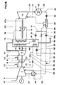
- Figure the Enzige shows a power plant, which consists of a gas turbine group, one of the Gas turbine group downstream heat recovery steam generator, and one Heat recovery steam generator downstream steam circuit exists.
- the present gas turbine group is based on sequential combustion.
- provision of the operation of the various Combustion chambers necessary fuel can for example by a coal gasification interacting with the gas turbine group become.
- it is also possible to use the one used Obtain fuel from a primary network.
- the present gas turbine group the can also act as an autonomous unit, consists of a compressor 1, one the first combustion chamber 2 downstream of the compressor, one of these combustion chambers 2 downstream first turbine 3, one downstream of this turbine 3 second combustion chamber 4 and one downstream of this combustion chamber 4 second turbine 5.
- the compressor 1 is provided with an intermediate cooling 36 equipped in which a preheated condensate 32 serves as a heat sink and is heated to hot water 39.
- the mentioned flow machines 1, 3, 5 have a uniform rotor shaft 47. This rotor shaft is preferred mounted on two bearings, which are not visible in the single figure, which preferably placed on the head side of the compressor 1 and downstream of the second turbine 5 are. Intercooling is discussed in more detail below.
- the sucked in Air 6 is compressed in the compressor 1 and then flows as compressed Air 7 in a housing, not shown.
- the first Combustion chamber 2 housed, which preferably as a coherent Annular combustion chamber is formed.
- the compressed air 7th provided to the first combustion chamber 2 from an air storage system, not shown become.
- the annular combustion chamber 2 has, on the head side, distributed over the circumference, a number of burners, not shown, which preferably as Premix burners are designed. As such, diffusion burners can also be used here Get involved.
- the big premix burners which function as main burners have to meet the small premix burners that the pilot burners have of this combustion chamber are, with respect to the burner air flowing through them the compressed air 7 from the compressor 1, in a size ratio to one another, that is determined on a case-by-case basis.
- the pilot burners work as self-moving premix burners, taking the air ratio remains almost constant.
- the main burner is switched on or off after certain system-specific requirements. Because the pilot burners in the entire load range with an ideal mixture, the NOx emissions are very low even at partial load.
- the rotating ones come Streamlines in the front area of the annular combustion chamber 2 very close to the Vortex centers of the pilot burner approach, so that an ignition in itself only with these Pilot burners is possible.
- the amount of fuel is fed in via the pilot burner, to the extent that it is turned off are, i.e. until the full amount of fuel is available.
- the configuration is chosen so that this point of the respective load shedding conditions of the Corresponds to the gas turbine group.
- the further increase in performance then takes place via the Main burner. At the peak load of the gas turbine group, there are also those Main burner fully controlled.
- the configuration initiated by the pilot burner "small” hot vortex centers between those of the main brands originating "large” cooler vertebral centers will also be extremely unstable a very good burn-out with lean operated main burners in the partial load range achieved with low CO and UHC emissions in addition to NOx emissions, i.e. the hot eddies of the pilot burner immediately penetrate the small eddies the main burner.
- This Turbine 3 will therefore consist of no more than two rows of blades. With such a turbine 3 it will be necessary to equalize the pressure on the end faces to stabilize the axial thrust.
- This second combustion chamber 4 has essentially the shape of a contiguous ring-shaped axial or quasi-axial ring cylinder.
- This Combustion chamber 4 can of course also consist of a number axially, quasi-axially or helically arranged and self-contained combustion chambers consist.
- This combustion chamber 4 has no burner: the Combustion of a partially released hot gas coming from the turbine 3 9 injected fuel 13 happens here by auto-ignition, as far as of course, the temperature level allows such an operating mode.
- the combustion chamber 4 with a gaseous fuel for example Natural gas
- a gaseous fuel for example Natural gas
- the outlet temperature of the partially released hot gases 9 from the turbine 3 still be very high, as set out above around 1000 ° C, and of course also at partial load operation, which is due to the interpretation of this Turbine 2 plays a causal role.
- a combustion chamber designed for self-ignition ensure that it is extremely important that the flame front is stable in place remains.
- this combustion chamber 4 preferably on the Inner and outer wall arranged in the circumferential direction, a number of not closer shown elements provided, which preferably in the axial direction are placed upstream of the fuel lances.
- the task of these elements is in creating vortices that have a backflow zone, analogous to that in the already mentioned premix burners. Since this is the combustion chamber 4, due to the axial arrangement and length, to a high-speed combustion chamber at which the average speed of the Working gas is greater than about 60 m / s, the vortex-producing elements must are designed to conform to the flow. On the inflow side, these should preferably consist of a tetrahedral shape with inclined surfaces.
- the vortex-generating elements can either be on the outer surface and / or be placed on the inner surface. Of course, the vortex generating Elements can also be shifted axially to one another.
- the outflow side The surface of the vortex-generating elements is essentially radial, so that there is a backflow zone from there.
- the auto ignition in the combustion chamber 4 must, however, also in the transient load ranges as well remain secured in the partial load range of the gas turbine group, i.e. auxiliary measures must be taken be provided, which is the auto-ignition in the combustion chamber 4 also ensure if there is a flexion of the temperature of the gases should stop in the area of fuel injection.
- auxiliary measures must be taken be provided, which is the auto-ignition in the combustion chamber 4 also ensure if there is a flexion of the temperature of the gases should stop in the area of fuel injection.
- auxiliary measures must be taken be provided, which is the auto-ignition in the combustion chamber 4 also ensure if there is a flexion of the temperature of the gases should stop in the area of fuel injection.
- Suitable as an auxiliary fuel here for example, fuel oil very well.
- the liquid auxiliary fuel fulfills the task of acting as a fuse and enables also auto-ignition in the combustion chamber 4 when the partially relaxed Hot gases 9 from the first turbine 3 a temperature below the target should have optimal levels of 1000 ° C.
- fuel oil Providing to ensure auto-ignition always proves itself then particularly appropriate if the gas turbine group with a greatly reduced Load is operated.
- This arrangement also makes a decisive contribution to that the combustion chamber 4 can have a minimal axial length.
- the short Overall length of the combustion chamber 4, the effect of the vortex-generating elements Flame stabilization and the continuous guarantee of auto-ignition are therefore responsible for ensuring that the combustion takes place very quickly, and the residence time of the fuel in the area of the hot flame front is minimal remains.
- This relates to an effect that can be measured directly in terms of combustion the NOx emissions, which are minimized so that they no longer form a topic.
- This starting position also enables the location the combustion clearly define what is in an optimized cooling of the Structures of this combustion chamber 4 precipitates.
- Hot gases 10 then act on a downstream one second turbine 5.
- the thermodynamic characteristics of the gas turbine group can be designed so that the exhaust gases 11 from the second turbine 5 have so much caloric potential, so that here with the help of a heat recovery steam generator 15 shown steam generation stage and steam cycle to operate.
- a heat recovery steam generator 15 shown steam generation stage and steam cycle to operate.
- the second between the outflow plane of the first turbine 3 and the inflow plane the second turbine 5 running combustion chamber 4 a minimal Length, because furthermore the expansion of the hot gases in the first turbine 3, for reasons set out, over a few, preferably only over 1 or 2 rows of blades a gas turbine group can be provided, the rotor shaft of which 47 due to their minimized length technically perfect on two bearings is supported.
- the power output of the turbomachines is done by a generator 14 coupled on the compressor side, which also serve as a starting motor can. After relaxation in the turbine 5, they still flow through with one high calorific potential provided exhaust gases 11 a heat recovery steam generator 15, in which steam is generated in various ways in heat exchange processes, which then forms the working medium of the downstream steam cycle.
- the calorically used exhaust gases then flow into the flue gases 30 ins Free.
- the waste heat steam generator 15 has a tube bundle 19 for reheating Steam, which acts on a low-pressure turbine 17 with medium-pressure steam 20. Furthermore, this heat recovery steam generator 15 has a tube bundle 33 in which a high pressure steam 34 for the application of a high pressure steam turbine 16 is provided, this steam having about 250 bar. The from this high pressure steam turbine 16 expanded steam 18 forms the medium for the tube bundle 19, in which a medium pressure steam 20 for application a low pressure steam turbine 17 is provided. Both steam turbines 16, 17 are preferably mounted on a shaft 47a and preferably not via one Coupling shown coupled to the rotor shaft 47 of the gas turbine group. A autonomous unit of the steam group with another generator is also possible. It is also possible to close the high-pressure steam turbine 16 at an increased speed operate and connect via gear or converter.
- the steam 21 expanded in the low-pressure steam turbine 17 is in a water or air-cooled (23) condenser 22 condenses.
- this Condenser 22 acting condensate pump 25 Through a downstream of this Condenser 22 acting condensate pump 25, the condensate 24 into one Feed water tank and degasser 26 promoted, which also as a mixer preheater is known.
- the condensate 24 is supplied by Hot water 39 preheated to about 60 ° C.
- a regulator 40 doses the amount of hot water so that the steam is stagnating in the pressure maintaining line 27.
- the condensate 28 from the degasser 26 is divided and over corresponding Conveying pumps 29, 29a forwarded.
- Part 31 of this condensate 28 forms the amount caused by an upstream of the tube bundle for superheated high pressure steam 33 acting economizer 43 is directed, this amount of Amount of expanded steam 21 from the low-pressure steam turbine 17 corresponds.
- the other part of the condensate 28 flows via a line 32 to one in operative connection with the compressor 1 intercooler 36.
- Heat emission of the partially compressed air 37 in the intercooler 36 becomes the condensate 32 processed to high pressure hot water 39, the cooled partially compressed Air 38 flows back into the compressor 1 for further pressure processing.
- the hot water 39 from the intercooler 36 is before Inflow branched into the degasser 26 and by means of a feed pump 42 passed through a further economizer 43a in the heat recovery steam generator 15 and then continues to heat up to the boiling point as hot water 44 in the Gas turbine group introduced at a suitable point.
- this hot water 44 via different control elements 45, 46 in different Aggregates of the gas turbine group can be injected in parallel, with series-retained ones Flow paths when introducing this hot water 44 are also possible are.
- the medium (39) is introduced upstream and / or into a combustion chamber. Furthermore, the medium (39) can also be enriched with a quantity of separating substance.
- the amount of this hot water 39 consumed by injection is upstream of the intercooler 36 by a corresponding amount of make-up water 35 replaced.
- the preheating in the intercooler 36 becomes thermodynamic at the latter optimal placement with a total pressure ratio of approx 30: 1 brought to approx. 130 ° C.
- the hot water still heats up to about 200 ° C.
- Under these conditions flows just about as much hot water 39 from the degasser Intercooler 36 to preheat the incoming condensate 24 can be done.
- With such a balanced balance sheet stagnates accordingly the amount of steam flowing through the pressure maintaining line 27 into the low-pressure steam turbine 17, hereby only for the stabilization of the negative pressure in Mixing heater 26 is taken care of. If the operating conditions deviate from the design point the mixing preheater 26 automatically fetches preheating steam from said steam turbine 17, or delivers flash steam there.
- the water consumption for the additional power gained by the intercooler 36 of the compressor 1 and by injecting an amount of steam 44 into the gas turbine corresponds approximately to the water consumption of an evaporative cooling tower of a modern power plant corresponding performance
Landscapes
- Engineering & Computer Science (AREA)
- Chemical & Material Sciences (AREA)
- Combustion & Propulsion (AREA)
- Mechanical Engineering (AREA)
- General Engineering & Computer Science (AREA)
- Engine Equipment That Uses Special Cycles (AREA)
Claims (8)
- Procédé de fonctionnement d'une centrale électrique se composant essentiellement d'un groupe générateur à turbines à gaz, d'un générateur de vapeur à chaleur perdue (15) et d'un circuit de vapeur placé en aval du générateur de vapeur à chaleur perdue (15), le groupe générateur à turbines à gaz se composant d'au moins une unité de compresseur (1) avec au moins un refroidisseur intermédiaire (36), au moins une chambre de combustion (2, 4), au moins une turbine (3, 5) et au moins un générateur (14) ou une charge, les gaz d'échappement (11) s'écoulant hors de la dernière turbine (5) à travers le générateur de vapeur à chaleur perdue (15), dans lequel on réalise la production d'au moins une vapeur pour faire fonctionner au moins une turbine à vapeur (16, 17) appartenant au circuit de vapeur, une partie du condensat (32) se formant à partir de la dernière turbine (17) étant traité dans un refroidisseur intermédiaire (36) pour fournir un milieu chaud (39, 41),
caractérisé en ce que
ce milieu est introduit dans le circuit du groupe générateur à turbines à gaz, et en ce qu'en amont du refroidisseur intermédiaire (36) une eau d'appoint (35) est introduite dans le condensat (32). - Procédé selon la revendication 1, caractérisé en ce que le milieu (39) est introduit directement dans le groupe générateur à turbines à gaz.
- Procédé selon la revendication 1, caractérisé en ce que le milieu (39) est introduit après un chauffage supplémentaire (43a) dans le groupe générateur à turbines à gaz.
- Procédé selon la revendication 1, caractérisé en ce que le milieu (39) est de l'eau chaude.
- Procédé selon la revendication 1, caractérisé en ce que le milieu (39) se compose d'un mélange d'eau chaude et de vapeur.
- Procédé selon la revendication 1, caractérisé en ce que le milieu (39) est introduit en amont d'une chambre de combustion (2, 4) et/ou dans celle-ci.
- Procédé selon la revendication 1, caractérisé en ce que le milieu (39) est enrichi avec une quantité de combustible.
- Procédé selon la revendication 1, caractérisé en ce que le chauffage supplémentaire du milieu (41) avant son introduction dans le groupe générateur à turbines à gaz est effectué dans une section d'économiseur (43a) appartenant au générateur de vapeur à chaleur perdue (15).
Priority Applications (5)
| Application Number | Priority Date | Filing Date | Title |
|---|---|---|---|
| EP97810532A EP0915232B1 (fr) | 1997-07-25 | 1997-07-25 | Procédé de fonctionnement d'une centrale d'énergie |
| DE59709403T DE59709403D1 (de) | 1997-07-25 | 1997-07-25 | Verfahren zum Betrieb einer Kraftwerksanlage |
| EP02009180A EP1243757B1 (fr) | 1997-07-25 | 1997-07-25 | Procédé de fonctionnement d'une centrale d'énergie |
| US09/116,933 US6223523B1 (en) | 1997-07-25 | 1998-07-17 | Method of operating a power station plant |
| JP10209255A JPH1193619A (ja) | 1997-07-25 | 1998-07-24 | 発電設備を運転する方法 |
Applications Claiming Priority (1)
| Application Number | Priority Date | Filing Date | Title |
|---|---|---|---|
| EP97810532A EP0915232B1 (fr) | 1997-07-25 | 1997-07-25 | Procédé de fonctionnement d'une centrale d'énergie |
Related Child Applications (1)
| Application Number | Title | Priority Date | Filing Date |
|---|---|---|---|
| EP02009180A Division EP1243757B1 (fr) | 1997-07-25 | 1997-07-25 | Procédé de fonctionnement d'une centrale d'énergie |
Publications (2)
| Publication Number | Publication Date |
|---|---|
| EP0915232A1 EP0915232A1 (fr) | 1999-05-12 |
| EP0915232B1 true EP0915232B1 (fr) | 2003-02-26 |
Family
ID=8230322
Family Applications (2)
| Application Number | Title | Priority Date | Filing Date |
|---|---|---|---|
| EP02009180A Expired - Lifetime EP1243757B1 (fr) | 1997-07-25 | 1997-07-25 | Procédé de fonctionnement d'une centrale d'énergie |
| EP97810532A Expired - Lifetime EP0915232B1 (fr) | 1997-07-25 | 1997-07-25 | Procédé de fonctionnement d'une centrale d'énergie |
Family Applications Before (1)
| Application Number | Title | Priority Date | Filing Date |
|---|---|---|---|
| EP02009180A Expired - Lifetime EP1243757B1 (fr) | 1997-07-25 | 1997-07-25 | Procédé de fonctionnement d'une centrale d'énergie |
Country Status (4)
| Country | Link |
|---|---|
| US (1) | US6223523B1 (fr) |
| EP (2) | EP1243757B1 (fr) |
| JP (1) | JPH1193619A (fr) |
| DE (1) | DE59709403D1 (fr) |
Families Citing this family (36)
| Publication number | Priority date | Publication date | Assignee | Title |
|---|---|---|---|---|
| GB9906620D0 (en) * | 1999-03-23 | 1999-05-19 | Rolls Royce Plc | Power generation equipment |
| US6539720B2 (en) * | 2000-11-06 | 2003-04-01 | Capstone Turbine Corporation | Generated system bottoming cycle |
| US20020163819A1 (en) * | 2000-11-07 | 2002-11-07 | Treece William A. | Hybrid microturbine/fuel cell system providing air contamination control |
| JP3716188B2 (ja) * | 2001-04-10 | 2005-11-16 | 三菱重工業株式会社 | ガスタービンコンバインドプラント |
| GB2382848A (en) * | 2001-12-06 | 2003-06-11 | Alstom | Gas turbine wet compression |
| GB2382847A (en) * | 2001-12-06 | 2003-06-11 | Alstom | Gas turbine wet compression |
| DE50209742D1 (de) * | 2002-01-07 | 2007-04-26 | Alstom Technology Ltd | Verfahren zum betrieb einer gasturbogruppe |
| US6685447B2 (en) | 2002-01-25 | 2004-02-03 | Hamilton Sundstrand | Liquid cooled integrated rotordynamic motor/generator station with sealed power electronic controls |
| NL1020350C2 (nl) * | 2002-04-10 | 2003-10-13 | Henk Ouwerkerk | Stoom- en gasturbine-inrichting. |
| EP1388643B1 (fr) * | 2002-08-09 | 2008-10-29 | Hitachi, Ltd. | Centrale combinée |
| DE10256193A1 (de) * | 2002-12-02 | 2004-06-09 | Alstom Technology Ltd | Verfahren zur Steuerung der Flüssigkeitseinspritzung in einen Zuströmkanal einer Kraft- oder Arbeitsmaschine |
| JP4002976B2 (ja) * | 2003-06-10 | 2007-11-07 | 独立行政法人産業技術総合研究所 | 負圧まで膨張する再熱ガスタービン装置 |
| US20050087987A1 (en) * | 2003-10-23 | 2005-04-28 | Mr. CHUN-MING KUO | [household emergency power generator] |
| JP4811991B2 (ja) * | 2005-07-06 | 2011-11-09 | 株式会社日立製作所 | 高湿分利用ガスタービン設備 |
| US20070017207A1 (en) * | 2005-07-25 | 2007-01-25 | General Electric Company | Combined Cycle Power Plant |
| ATE496206T1 (de) * | 2005-10-12 | 2011-02-15 | Alstom Technology Ltd | Gasturbine mit geregelter luftkühlung |
| US8085990B2 (en) * | 2006-07-28 | 2011-12-27 | Microsoft Corporation | Hybrid maps with embedded street-side images |
| JP4371278B2 (ja) * | 2007-08-07 | 2009-11-25 | 株式会社日立製作所 | 高湿分利用ガスタービン設備 |
| RU2353787C1 (ru) * | 2007-09-06 | 2009-04-27 | Открытое акционерное общество "Российские железные дороги" (ОАО "РЖД") | Газотурбинная установка |
| US20090301078A1 (en) * | 2008-06-10 | 2009-12-10 | General Electric Company | System for recovering the waste heat generated by an auxiliary system of a turbomachine |
| DE102010042792A1 (de) * | 2010-10-22 | 2012-04-26 | Man Diesel & Turbo Se | System zur Erzeugung mechanischer und/oder elektrischer Energie |
| US8640437B1 (en) * | 2011-02-24 | 2014-02-04 | Florida Turbine Technologies, Inc. | Mini sized combined cycle power plant |
| EP2620732A1 (fr) * | 2012-01-26 | 2013-07-31 | Linde Aktiengesellschaft | Procédé et dispositif de séparation de l'air et de production de vapeur dans un système combiné |
| EP2642091A1 (fr) * | 2012-03-22 | 2013-09-25 | Siemens Aktiengesellschaft | Centrale électrique à cycle combiné |
| JP5983213B2 (ja) * | 2012-09-10 | 2016-08-31 | 東京電力ホールディングス株式会社 | 超臨界蒸気複合サイクル |
| JP6183759B2 (ja) * | 2013-04-22 | 2017-08-23 | パナソニックIpマネジメント株式会社 | 熱電併給システム |
| DE102013213836A1 (de) | 2013-07-15 | 2015-01-15 | Magna Powertrain Ag & Co. Kg | Expansionsmaschine |
| US10914200B2 (en) * | 2013-10-31 | 2021-02-09 | General Electric Technology Gmbh | Combined cycle power plant with improved efficiency |
| US10118108B2 (en) | 2014-04-22 | 2018-11-06 | General Electric Company | System and method of distillation process and turbine engine intercooler |
| US10024195B2 (en) * | 2015-02-19 | 2018-07-17 | General Electric Company | System and method for heating make-up working fluid of a steam system with engine fluid waste heat |
| DE102015109898A1 (de) * | 2015-02-20 | 2016-08-25 | Mitsubishi Hitachi Power Systems Europe Gmbh | Dampfkraftwerk und Verfahren zu dessen Betrieb |
| ES2585879B1 (es) * | 2015-04-10 | 2017-07-25 | Luis Carlos Sepulveda Montilla | Máquina térmica con ciclo termodinámico y procedimiento de funcionamiento de la misma |
| US10487695B2 (en) | 2015-10-23 | 2019-11-26 | General Electric Company | System and method of interfacing intercooled gas turbine engine with distillation process |
| EP3216989A1 (fr) * | 2016-03-11 | 2017-09-13 | NEM Energy B.V. | Centrale electrique à cycle combiné |
| US10710745B2 (en) * | 2016-09-08 | 2020-07-14 | Voltaire Incorporated | Engine driven air compressor system for a mobile aviation support cart |
| CN108952862B (zh) * | 2018-07-25 | 2019-09-20 | 清华大学 | 回热式压缩空气储能系统及其使用方法 |
Family Cites Families (14)
| Publication number | Priority date | Publication date | Assignee | Title |
|---|---|---|---|---|
| CH456250A (de) * | 1966-05-06 | 1968-05-15 | Sulzer Ag | Verfahren zum gemischten Gas- und Dampfbetrieb einer Gasturbinenanlage sowie Anlage zur Ausübung des Verfahrens |
| CH480535A (de) | 1968-03-06 | 1969-10-31 | Escher Wyss Ag | Wärmekraftanlage für die Ausnützung der in einem Kernreaktor erzeugten Wärme, mit einer kombinierten Gasturbinen- Dampfturbinenanlage |
| DE2138664C3 (de) * | 1971-07-23 | 1974-01-24 | Gebrueder Sulzer Ag, Winterthur (Schweiz) | Gas-Dampfturbinenanlage |
| FR2230864A1 (en) * | 1973-05-22 | 1974-12-20 | Electricite De France | Fluid transfer system for gas turbine installation - compressor heat exchangers uses hot exhaust to heat injection fluid |
| US4537023A (en) * | 1981-12-10 | 1985-08-27 | Mitsubishi Gas Chemical Company, Inc. | Regenerative gas turbine cycle |
| US4569195A (en) * | 1984-04-27 | 1986-02-11 | General Electric Company | Fluid injection gas turbine engine and method for operating |
| CH674561A5 (fr) | 1987-12-21 | 1990-06-15 | Bbc Brown Boveri & Cie | |
| DE3815993A1 (de) * | 1988-05-10 | 1989-11-23 | Rudolf Dr Wieser | Zweistoff-turbinenanlage |
| US4932204A (en) * | 1989-04-03 | 1990-06-12 | Westinghouse Electric Corp. | Efficiency combined cycle power plant |
| DE4118062A1 (de) * | 1991-06-01 | 1992-12-03 | Asea Brown Boveri | Kombinierte gas/dampf-kraftwerksanlage |
| DE4237664A1 (de) * | 1992-11-07 | 1994-05-11 | Asea Brown Boveri | Verfahren zum Betrieb eines Turboverdichters |
| DE4237665A1 (de) * | 1992-11-07 | 1994-05-11 | Asea Brown Boveri | Verfahren zum Betrieb einer Kombianlage |
| DE19615911A1 (de) * | 1996-04-22 | 1997-10-23 | Asea Brown Boveri | Verfahren zum Betrieb einer Kombianlage |
| US6089024A (en) * | 1998-11-25 | 2000-07-18 | Elson Corporation | Steam-augmented gas turbine |
-
1997
- 1997-07-25 EP EP02009180A patent/EP1243757B1/fr not_active Expired - Lifetime
- 1997-07-25 EP EP97810532A patent/EP0915232B1/fr not_active Expired - Lifetime
- 1997-07-25 DE DE59709403T patent/DE59709403D1/de not_active Expired - Fee Related
-
1998
- 1998-07-17 US US09/116,933 patent/US6223523B1/en not_active Expired - Fee Related
- 1998-07-24 JP JP10209255A patent/JPH1193619A/ja active Pending
Also Published As
| Publication number | Publication date |
|---|---|
| JPH1193619A (ja) | 1999-04-06 |
| US6223523B1 (en) | 2001-05-01 |
| EP0915232A1 (fr) | 1999-05-12 |
| EP1243757A1 (fr) | 2002-09-25 |
| EP1243757B1 (fr) | 2005-12-07 |
| DE59709403D1 (de) | 2003-04-03 |
Similar Documents
| Publication | Publication Date | Title |
|---|---|---|
| EP0915232B1 (fr) | Procédé de fonctionnement d'une centrale d'énergie | |
| EP0731255B1 (fr) | Système de turbine pour centrales d'électricité | |
| EP0795685B1 (fr) | Turbine à gaz multi-étagée avec refroidissement par vapeur et réinjection en chambre de combustion | |
| EP0808994B1 (fr) | Procédé de fonctionnement d'une centrale combinée | |
| EP0620362B1 (fr) | Turbine à gaz | |
| EP0768449B1 (fr) | Procédé de fonctionnement d'une centrale d'énergie | |
| EP1432889B1 (fr) | Procede et dispositif permettant de demarrer des centrales thermiques a gaz exemptes d'emissions | |
| EP0778397B1 (fr) | Procédé d'opération d'une centrale combinée avec une chaudière de récuperation et un consommateur de vapeur | |
| DE19745272C2 (de) | Gas- und Dampfturbinenanlage und Verfahren zum Betreiben einer derartigen Anlage | |
| DE10041413B4 (de) | Verfahren zum Betrieb einer Kraftwerksanlage | |
| EP0767290B1 (fr) | Procédé de fonctionnement d'une centrale d'énergie | |
| EP0591163B2 (fr) | Installation combinee a turbines a gaz et a vapeur | |
| EP0789134B1 (fr) | Procédé de fonctionnement d'une centrale d'énergie | |
| WO2010069671A1 (fr) | Générateur de vapeur à récupération de chaleur et procédé pour améliorer le fonctionnement d'un générateur de vapeur à récupération de chaleur | |
| EP0773349A1 (fr) | Refroidisseur d'air de refroidissement pour centrales | |
| DE19900026B4 (de) | Gasturbine mit Dampfeindüsung | |
| EP0978635B1 (fr) | Procédé pour refroidir les structures thermiquement chargées d'une centrale thermique | |
| EP0899438B1 (fr) | Turbine à gaz avec générateur à récupération de vapeur surchaufée pour injection dans la chambre de combustion et de vapeur saturante pour refroidissement puis injection dans la chambre de combustion | |
| EP0709561A1 (fr) | Centrale électrique | |
| DE19961383A1 (de) | Verfahren zum Betrieb einer Kraftwerksanlage | |
| EP0887539A2 (fr) | Turboréacteur | |
| DE10116117A1 (de) | Verfahren zur Kühlung der thermisch belasteten Strukturen einer Kraftwerksanlage | |
| EP0770770B1 (fr) | Procédé de fonctionnement d'un groupe turbo à gaz | |
| DE19961385A1 (de) | Verfahren zum Betrieb einer Kraftwerksanlage |
Legal Events
| Date | Code | Title | Description |
|---|---|---|---|
| PUAI | Public reference made under article 153(3) epc to a published international application that has entered the european phase |
Free format text: ORIGINAL CODE: 0009012 |
|
| AK | Designated contracting states |
Kind code of ref document: A1 Designated state(s): DE GB |
|
| AX | Request for extension of the european patent |
Free format text: AL;LT;LV;RO;SI |
|
| 17P | Request for examination filed |
Effective date: 19991014 |
|
| AKX | Designation fees paid |
Free format text: DE GB |
|
| RAP1 | Party data changed (applicant data changed or rights of an application transferred) |
Owner name: ALSTOM |
|
| 17Q | First examination report despatched |
Effective date: 20011213 |
|
| GRAG | Despatch of communication of intention to grant |
Free format text: ORIGINAL CODE: EPIDOS AGRA |
|
| GRAG | Despatch of communication of intention to grant |
Free format text: ORIGINAL CODE: EPIDOS AGRA |
|
| GRAH | Despatch of communication of intention to grant a patent |
Free format text: ORIGINAL CODE: EPIDOS IGRA |
|
| GRAH | Despatch of communication of intention to grant a patent |
Free format text: ORIGINAL CODE: EPIDOS IGRA |
|
| RAP1 | Party data changed (applicant data changed or rights of an application transferred) |
Owner name: ALSTOM (SWITZERLAND) LTD |
|
| GRAA | (expected) grant |
Free format text: ORIGINAL CODE: 0009210 |
|
| AK | Designated contracting states |
Designated state(s): DE GB |
|
| REG | Reference to a national code |
Ref country code: GB Ref legal event code: FG4D Free format text: NOT ENGLISH |
|
| REF | Corresponds to: |
Ref document number: 59709403 Country of ref document: DE Date of ref document: 20030403 Kind code of ref document: P |
|
| GBT | Gb: translation of ep patent filed (gb section 77(6)(a)/1977) |
Effective date: 20030512 |
|
| PLBE | No opposition filed within time limit |
Free format text: ORIGINAL CODE: 0009261 |
|
| STAA | Information on the status of an ep patent application or granted ep patent |
Free format text: STATUS: NO OPPOSITION FILED WITHIN TIME LIMIT |
|
| 26N | No opposition filed |
Effective date: 20031127 |
|
| PGFP | Annual fee paid to national office [announced via postgrant information from national office to epo] |
Ref country code: DE Payment date: 20080722 Year of fee payment: 12 |
|
| PGFP | Annual fee paid to national office [announced via postgrant information from national office to epo] |
Ref country code: GB Payment date: 20080722 Year of fee payment: 12 |
|
| GBPC | Gb: european patent ceased through non-payment of renewal fee |
Effective date: 20090725 |
|
| PG25 | Lapsed in a contracting state [announced via postgrant information from national office to epo] |
Ref country code: GB Free format text: LAPSE BECAUSE OF NON-PAYMENT OF DUE FEES Effective date: 20090725 |
|
| PG25 | Lapsed in a contracting state [announced via postgrant information from national office to epo] |
Ref country code: DE Free format text: LAPSE BECAUSE OF NON-PAYMENT OF DUE FEES Effective date: 20100202 |