US6539720B2 - Generated system bottoming cycle - Google Patents
Generated system bottoming cycle Download PDFInfo
- Publication number
- US6539720B2 US6539720B2 US09/985,789 US98578901A US6539720B2 US 6539720 B2 US6539720 B2 US 6539720B2 US 98578901 A US98578901 A US 98578901A US 6539720 B2 US6539720 B2 US 6539720B2
- Authority
- US
- United States
- Prior art keywords
- turbogenerator
- turbo expander
- closed loop
- turbine
- heat exchanger
- Prior art date
- Legal status (The legal status is an assumption and is not a legal conclusion. Google has not performed a legal analysis and makes no representation as to the accuracy of the status listed.)
- Expired - Lifetime
Links
Images


Classifications
-
- F—MECHANICAL ENGINEERING; LIGHTING; HEATING; WEAPONS; BLASTING
- F01—MACHINES OR ENGINES IN GENERAL; ENGINE PLANTS IN GENERAL; STEAM ENGINES
- F01K—STEAM ENGINE PLANTS; STEAM ACCUMULATORS; ENGINE PLANTS NOT OTHERWISE PROVIDED FOR; ENGINES USING SPECIAL WORKING FLUIDS OR CYCLES
- F01K23/00—Plants characterised by more than one engine delivering power external to the plant, the engines being driven by different fluids
- F01K23/02—Plants characterised by more than one engine delivering power external to the plant, the engines being driven by different fluids the engine cycles being thermally coupled
- F01K23/06—Plants characterised by more than one engine delivering power external to the plant, the engines being driven by different fluids the engine cycles being thermally coupled combustion heat from one cycle heating the fluid in another cycle
- F01K23/10—Plants characterised by more than one engine delivering power external to the plant, the engines being driven by different fluids the engine cycles being thermally coupled combustion heat from one cycle heating the fluid in another cycle with exhaust fluid of one cycle heating the fluid in another cycle
-
- F—MECHANICAL ENGINEERING; LIGHTING; HEATING; WEAPONS; BLASTING
- F01—MACHINES OR ENGINES IN GENERAL; ENGINE PLANTS IN GENERAL; STEAM ENGINES
- F01K—STEAM ENGINE PLANTS; STEAM ACCUMULATORS; ENGINE PLANTS NOT OTHERWISE PROVIDED FOR; ENGINES USING SPECIAL WORKING FLUIDS OR CYCLES
- F01K25/00—Plants or engines characterised by use of special working fluids, not otherwise provided for; Plants operating in closed cycles and not otherwise provided for
- F01K25/08—Plants or engines characterised by use of special working fluids, not otherwise provided for; Plants operating in closed cycles and not otherwise provided for using special vapours
-
- F—MECHANICAL ENGINEERING; LIGHTING; HEATING; WEAPONS; BLASTING
- F02—COMBUSTION ENGINES; HOT-GAS OR COMBUSTION-PRODUCT ENGINE PLANTS
- F02C—GAS-TURBINE PLANTS; AIR INTAKES FOR JET-PROPULSION PLANTS; CONTROLLING FUEL SUPPLY IN AIR-BREATHING JET-PROPULSION PLANTS
- F02C6/00—Plural gas-turbine plants; Combinations of gas-turbine plants with other apparatus; Adaptations of gas-turbine plants for special use
- F02C6/18—Plural gas-turbine plants; Combinations of gas-turbine plants with other apparatus; Adaptations of gas-turbine plants for special use using the waste heat of gas-turbine plants outside the plants themselves, e.g. gas-turbine power heat plants
Definitions
- the present invention relates to a closed loop Rankine bottoming cycle for a generator system, and more particularly to a recuperated or simple cycle MICRO-TURBINE engine, MICRO-TURBINE/fuel cell hybrid engine or individual fuel cells of various types.
- the present invention solves the above-noted and other problems by providing a novel closed loop Rankine bottoming cycle including a heat exchanger coupled to an exhaust port of a first turbogenerator for heating a pressurized refrigerant into a gaseous phase, and a second turbogenerator (e.g., a turbo expander) coupled to the heat exchanger for expanding the gaseous phase so as to create power. Also included is a cooling mechanism coupled to an exhaust of the second turbogenerator for cooling the gaseous phase exhausted by the second turbogenerator into a liquid phase, and a pumping mechanism for pressurizing the liquid phase into the pressurized refrigerant heated by the heat exchanger.
- a heat exchanger coupled to an exhaust port of a first turbogenerator for heating a pressurized refrigerant into a gaseous phase
- a second turbogenerator e.g., a turbo expander
- a cooling mechanism coupled to an exhaust of the second turbogenerator for cooling the gaseous phase exhausted
- the present invention also includes a method and computer program product for operating and synchronizing the generator included in the closed loop, so as to optimize the overall system efficiency.
- FIG. 1A is perspective view, partially in section, of an integrated turbogenerator system.
- FIG. 1B is a magnified perspective view, partially in section, of the motor/generator portion of the integrated turbogenerator of FIG. 1 A.
- FIG. 1C is an end view, from the motor/generator end, of the integrated turbogenerator of FIG. 1 A.
- FIG. 1D is a magnified perspective view, partially in section, of the combustor-turbine exhaust portion of the integrated turbogenerator of FIG. 1 A.
- FIG. 1E is a magnified perspective view, partially in section, of the compressor-turbine portion of the integrated turbogenerator of FIG. 1 A.
- FIG. 2 is a block diagram schematic of a turbogenerator system including a power controller having decoupled rotor speed, operating temperature, and DC bus voltage control loops.
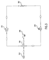
- FIG. 3 is a schematic illustrating a closed loop Rankine bottoming cycle for a generator system according to the present invention.
- FIG. 4 is schematic illustrating an alternative closed loop Rankine bottoming cycle for a generator system according to the present invention.
- an integrated turbogenerator 1 generally includes motor/generator section 10 and compressor-turbine section 30 .
- Compressor-turbine section 30 includes exterior can 32 , compressor 40 , combustor 50 and turbine 70 .
- a recuperator 90 may be optionally included.
- motor/generator section 10 may be a permanent magnet motor generator having a permanent magnet rotor or sleeve 12 . Any other suitable type of motor generator may also be used.
- Permanent magnet rotor or sleeve 12 may contain a permanent magnet 12 M. Permanent magnet rotor or sleeve 12 and the permanent magnet disposed therein are rotatably supported within permanent magnet motor/generator stator 14 .
- one or more compliant foil, fluid film, radial, or journal bearings 15 A and 15 B rotatably support permanent magnet rotor or sleeve 12 and the permanent magnet disposed therein.
- All bearings, thrust, radial or journal bearings, in turbogenerator 1 may be fluid film bearings or compliant foil bearings.
- Motor/generator housing 16 encloses stator heat exchanger 17 having a plurality of radially extending stator cooling fins 18 .
- Stator cooling fins 18 connect to or form part of stator 14 and extend into annular space 10 A between motor/generator housing 16 and stator 14 .
- Wire windings 14 W exist on permanent magnet motor/generator stator 14 .
- combustor 50 may include cylindrical inner wall 52 and cylindrical outer wall 54 .
- Cylindrical outer wall 54 may also include air inlets 55 .
- Cylindrical walls 52 and 54 define an annular interior space 50 S in combustor 50 defining an axis 50 A.
- Combustor 50 includes a generally annular wall 56 further defining one axial end of the annular interior space of combustor 50 .
- Associated with combustor 50 may be one or more fuel injector inlets 58 to accommodate fuel injectors which receive fuel from fuel control element 50 P as shown in FIG. 2, and inject fuel or a fuel air mixture to interior of 50 S combustor 50 .
- Inner cylindrical surface 53 is interior to cylindrical inner wall 52 and forms exhaust duct 59 for turbine 70 .
- Turbine 70 may include turbine wheel 72 .
- An end of combustor 50 opposite annular wall 56 further defines an aperture 71 in turbine 70 exposed to turbine wheel 72 .
- Bearing rotor 74 may include a radially extending thrust bearing portion, bearing rotor thrust disk 78 , constrained by bilateral thrust bearings 78 A and 78 B.
- Bearing rotor 74 may be rotatably supported by one or more journal bearings 75 within center bearing housing 79 .
- Bearing rotor thrust disk 78 at the compressor end of bearing rotor 74 is rotatably supported preferably by a bilateral thrust bearing 78 A and 78 B.
- Journal or radial bearing 75 and thrust bearings 78 A and 78 B may be fluid film or foil bearings.
- Turbine wheel 72 , bearing rotor 74 and compressor impeller 42 may be mechanically constrained by tie bolt 74 B, or other suitable technique, to rotate when turbine wheel 72 rotates.
- Mechanical link 76 mechanically constrains compressor impeller 42 to permanent magnet rotor or sleeve 12 and the permanent magnet disposed therein causing permanent magnet rotor or sleeve 12 and the permanent magnet disposed therein to rotate when compressor impeller 42 rotates.
- compressor 40 may include compressor impeller 42 and compressor impeller housing 44 .
- Recuperator 90 may have an annular shape defined by cylindrical recuperator inner wall 92 and cylindrical recuperator outer wall 94 .
- Recuperator 90 contains internal passages for gas flow, one set of passages, passages 33 connecting from compressor 40 to combustor 50 , and one set of passages, passages 97 , connecting from turbine exhaust 80 to turbogenerator exhaust output 2 .
- Motor/generator cooling air 24 flows into annular space 10 A between motor/generator housing 16 and permanent magnet motor/generator stator 14 along flow path 24 A. Heat is exchanged from stator cooling fins 18 to generator cooling air 24 in flow path 24 A, thereby cooling stator cooling fins 18 and stator 14 and forming heated air 24 B.
- Rotor cooling air 28 passes around stator end 13 A and travels along rotor or sleeve 12 .
- Stator return cooling air 27 enters one or more cooling ducts 14 D and is conducted through stator 14 to provide further cooling.
- Stator return cooling air 27 and rotor cooling air 28 rejoin in stator cavity 29 and are drawn out of the motor/generator 10 by exhaust fan 11 which is connected to rotor or sleeve 12 and rotates with rotor or sleeve 12 .
- Exhaust air 27 B is conducted away from primary air inlet 20 by duct 10 D.
- compressor 40 receives compressor air 22 .
- Compressor impeller 42 compresses compressor air 22 and forces compressed gas 22 C to flow into a set of passages 33 in recuperator 90 connecting compressor 40 to combustor 50 .
- heat is exchanged from walls 98 of recuperator 90 to compressed gas 22 C.
- heated compressed gas 22 H flows out of recuperator 90 to space 35 between cylindrical inner surface 82 of turbine exhaust 80 and cylindrical outer wall 54 of combustor 50 .
- Heated compressed gas 22 H may flow into combustor 54 through sidewall ports 55 or main inlet 57 .
- Fuel (not shown) may be reacted in combustor 50 , converting chemically stored energy to heat.
- Hot compressed gas 51 in combustor 50 flows through turbine 70 forcing turbine wheel 72 to rotate. Movement of surfaces of turbine wheel 72 away from gas molecules partially cools and decompresses gas 51 D moving through turbine 70 .
- Turbine 70 is designed so that exhaust gas 107 flowing from combustor 50 through turbine 70 enters cylindrical passage 59 . Partially cooled and decompressed gas in cylindrical passage 59 flows axially in a direction away from permanent magnet motor/generator section 10 , and then radially outward, and then axially in a direction toward permanent magnet motor/generator section 10 to passages 97 of recuperator 90 , as indicated by gas flow arrows 108 and 109 respectively.
- low pressure catalytic reactor 80 A may be included between fuel injector inlets 58 and recuperator 90 .
- Low pressure catalytic reactor 80 A may include internal surfaces (not shown) having catalytic material (e.g., Pd or Pt, not shown) disposed on them.
- Low pressure catalytic reactor 80 A may have a generally annular shape defined by cylindrical inner surface 82 and cylindrical low pressure outer surface 84 . Unreacted and incompletely reacted hydrocarbons in gas in low pressure catalytic reactor 80 A react to convert chemically stored energy into additional heat, and to lower concentrations of partial reaction products, such as harmful emissions including nitrous oxides (NOx).
- NOx nitrous oxides
- Gas 110 flows through passages 97 in recuperator 90 connecting from turbine exhaust 80 or catalytic reactor 80 A to turbogenerator exhaust output 2 , as indicated by gas flow arrow 112 , and then exhausts from turbogenerator 1 , as indicated by gas flow arrow 113 .
- Gas flowing through passages 97 in recuperator 90 connecting from turbine exhaust 80 to outside of turbogenerator 1 exchanges heat to walls 98 of recuperator 90 .
- Walls 98 of recuperator 90 heated by gas flowing from turbine exhaust 80 exchange heat to gas 22 C flowing in recuperator 90 from compressor 40 to combustor 50 .
- Turbogenerator 1 may also include various electrical sensor and control lines for providing feedback to power controller 201 and for receiving and implementing control signals as shown in FIG. 2 .
- the integrated turbogenerator disclosed above is exemplary. Several alternative structural embodiments are known.
- air 22 may be replaced by a gaseous fuel mixture.
- fuel injectors may not be necessary.
- This embodiment may include an air and fuel mixer upstream of compressor 40 .
- fuel may be conducted directly to compressor 40 , for example by a fuel conduit connecting to compressor impeller housing 44 .
- Fuel and air may be mixed by action of the compressor impeller 42 .
- fuel injectors may not be necessary.
- combustor 50 may be a catalytic combustor.
- Permanent magnet motor/generator section 10 and compressor/combustor section 30 may have low pressure catalytic reactor 80 A outside of annular recuperator 90 , and may have recuperator 90 outside of low pressure catalytic reactor 80 A.
- Low pressure catalytic reactor 80 A may be disposed at least partially in cylindrical passage 59 , or in a passage of any shape confined by an inner wall of combustor 50 .
- Combustor 50 and low pressure catalytic reactor 80 A may be substantially or completely enclosed with an interior space formed by a generally annularly shaped recuperator 90 , or a recuperator 90 shaped to substantially enclose both combustor 50 and low pressure catalytic reactor 80 A on all but one face.
- An integrated turbogenerator is a turbogenerator in which the turbine, compressor, and generator are all constrained to rotate based upon rotation of the shaft to which the turbine is connected.
- the methods and apparatus disclosed herein are preferably but not necessarily used in connection with a turbogenerator, and preferably but not necessarily used in connection with an integrated turbogenerator.
- a turbogenerator system 200 includes power controller 201 which has three substantially decoupled control loops for controlling (1) rotary speed, (2) temperature, and (3) DC bus voltage.
- power controller 201 which has three substantially decoupled control loops for controlling (1) rotary speed, (2) temperature, and (3) DC bus voltage.
- turbogenerator system 200 includes integrated turbogenerator 1 and power controller 201 .
- Power controller 201 includes three decoupled or independent control loops.
- a first control loop, temperature control loop 228 regulates a temperature related to the desired operating temperature of primary combustor 50 to a set point, by varying fuel flow from fuel control element 50 P to primary combustor 50 .
- Temperature controller 228 C receives a temperature set point, T*, from temperature set point source 232 , and receives a measured temperature from temperature sensor 226 S connected to measured temperature line 226 .
- Temperature controller 228 C generates and transmits over fuel control signal line 230 to fuel pump 50 P a fuel control signal for controlling the amount of fuel supplied by fuel pump 50 P to primary combustor 50 to an amount intended to result in a desired operating temperature in primary combustor 50 .
- Temperature sensor 226 S may directly measure the temperature in primary combustor 50 or may measure a temperature of an element or area from which the temperature in the primary combustor 50 may be inferred.
- a second control loop, speed control loop 216 controls speed of the shaft common to the turbine 70 , compressor 40 , and motor/generator 10 , hereafter referred to as the common shaft, by varying torque applied by the motor generator to the common shaft. Torque applied by the motor generator to the common shaft depends upon power or current drawn from or pumped into windings of motor/generator 10 .
- Bi-directional generator power converter 202 is controlled by rotor speed controller 216 C to transmit power or current in or out of motor/generator 10 , as indicated by bi-directional arrow 242 .
- a sensor in turbogenerator 1 senses the rotary speed on the common shaft and transmits that rotary speed signal over measured speed line 220 .
- Rotor speed controller 216 receives the rotary speed signal from measured speed line 220 and a rotary speed set point signal from a rotary speed set point source 218 .
- Rotary speed controller 216 C generates and transmits to generator power converter 202 a power conversion control signal on line 222 controlling generator power converter 202 's transfer of power or current between AC lines 203 (i.e., from motor/generator 10 ) and DC bus 204 .
- Rotary speed set point source 218 may convert to the rotary speed set point a power set point P* received from power set point source 224 .
- a third control loop, voltage control loop 234 controls bus voltage on DC bus 204 to a set point by transferring power or voltage between DC bus 204 and any of (1) Load/Grid 208 and/or (2) energy storage device 210 , and/or (3) by transferring power or voltage from DC bus 204 to dynamic brake resistor 214 .
- a sensor measures voltage DC bus 204 and transmits a measured voltage signal over measured voltage line 236 .
- Bus voltage controller 234 C receives the measured voltage signal from voltage line 236 and a voltage set point signal V* from voltage set point source 238 .
- Bus voltage controller 234 C generates and transmits signals to bi-directional load power converter 206 and bi-directional battery power converter 212 controlling their transmission of power or voltage between DC bus 204 , load/grid 208 , and energy storage device 210 , respectively. In addition, bus voltage controller 234 transmits a control signal to control connection of dynamic brake resistor 214 to DC bus 204 .
- Power controller 201 regulates temperature to a set point by varying fuel flow, adds or removes power or current to motor/generator 10 under control of generator power converter 202 to control rotor speed to a set point as indicated by bi-directional arrow 242 , and controls bus voltage to a set point by (1) applying or removing power from DC bus 204 under the control of load power converter 206 as indicated by bi-directional arrow 244 , (2) applying or removing power from energy storage device 210 under the control of battery power converter 212 , and (3) by removing power from DC bus 204 by modulating the connection of dynamic brake resistor 214 to DC bus 204 .
- the closed loop bottoming cycle includes a heat exchanger 306 coupled to an exhaust port 308 of a first turbogenerator (e.g., the exhaust 113 of the turbogenerator 1 illustrated in FIG. 2 ).
- the first turbogenerator may also be a recuperated or simple cycle MICRO-TURBINE engine, MICRO-TURBINE/fuel cell hybrid engine or individual fuel cells of various types.
- the heat exchanger 306 is a fluid container including a high pressure refrigerant.
- a second turbogenerator 300 coupled to the heat exchanger 306 for expanding the gaseous phase created by the heat exchanger so as to create power.
- the exhaust from the first turbogenerator is used to heat the high pressure refrigerant included in the heat exchanger.
- the pressurized refrigerant included in the heat exchanger 306 is converted into a gaseous phase and the temperature of the gas is also significantly raised.
- the high pressure gases are then expanded through the second turbogenerator 300 to create power for generating electricity and/or driving the refrigerant compressor (not shown) included in the heat exchanger.
- the excess gas on the downstream side of the second turbogenerator 300 is passed through a cooler 302 so that the gas is cooled back down to its liquid or primarily liquid phase.
- the gas may be cooled using external cool air, for example.
- the liquid is then pumped up to a high pressure state before it reenters the heat exchanger 306 via a pumping mechanism 304 .
- the pumping mechanism 304 can be either electrically driven or driven mechanically by the second turbogenerator 300 .
- the pumping mechanism 304 may also use gas foil bearings, such as those disclosed in U.S. Pat. Nos. 5.529,398 and 5,791,868, both of which are incorporated in their entirety by reference.
- the first turbogenerator (e.g., MICRO-TURBINE) may be operated on a variety of fuels including natural gas, propane, hydrogen, bio gas, kerosine and diesel, for example. Further, the first turbogenerator may be driven from a variety of external heat sources such as solar energy or wood burning gas fires.
- the second turbogenerator 300 is preferably a small high speed expander (turbo expander) in the form of a radial turbine, axial turbine or Pellet wheel type of turbine that is optimized for the bottoming cycle.
- turbo expander a small high speed expander
- the rotating speed of the turbo expander shaft is configured to vary so as to optimize the performance of the turbo expander. This feature will be discussed in more detail later.
- the second turbogenerator 300 also directly drives a permanent magnet generator so as to create the alternating current.
- the permanent magnet generator may be integral to the rotor shaft or attached with a coupling device such as the double diaphragm shaft disclosed in U.S. Pat. Nos. 5,964,663 and 6,037,687, both of which are incorporated in their entirety herein.
- the exhaust from the MICRO-TURBINE or fuel cell (first turbogenerator) is used to heat the high pressure refrigerant via the heat exchanger 308 which is converted into an alternating current by the second turbogenerator 300 . Therefore, the heat from the exhaust of the MICRO-TURBINE 308 is not wasted, but is utilized so as to produce additional power. Further, the disclosed closed loop Rankine bottoming cycle according to the present invention has not previously been applied to generators as there was generally insufficient exhaust heat to produce a required output power, and because the overall system efficiency did not warrant practical implication.
- a high speed expander is used in combination with a MICRO-TURBINE generator system, for example, and the turbo expander (second turbogenerator 300 ) is controlled so as to be synchronized with the first turbogenerator (such as the MICRO-TURBINE or the fuel cell).
- the present invention includes control software which optimizes the system efficiency for the required load by adjusting the MICRO-TURBINE and bottoming cycle.
- the power and speed or the turbo expander may be controlled by adjusting the drive speed of compressor if it is electrically driven or by using a flow control valve if it is mechanically driven by the turbine expander.
- a diverter valve may also be required to divert the MICRO-TURBINE or fuel cell exhaust away from the bottoming cycle heat exchanger when the bottoming cycle is shut down, needs to operate at a reduced power, or the heat needs to be controlled to prevent damage to the bottoming cycle components or refrigerant.
- the diverter valve may be controlled by maintaining the maximum refrigerant temperature at a constant temperature.
- FIG. 4 illustrates an alternative closed loop Rankine bottoming cycle for optimal performance.
- the cycle includes a diverter valve 322 for diverting exhaust 320 from a MICRO-TURBINE, an evaporator 324 , temperature and pressure sensors 326 , a bypass valve 330 , a shut-off valve 332 , a bearing purge valve 334 , a turbine 336 , and a generator 338 .
- a condenser 340 Also included is a condenser 340 , a condenser control valve 344 , a pump drive 346 and a pump 348 .
- the bottoming cycle shown in FIG. 4 operates in a similar fashion as that as shown in FIG. 3 .
- the bottoming cycle in this arrangement is designed to allow the condenser pressure to vary, which in turn lets the dew point vary.
- the dew point in the condenser should be as close to ambient temperature as possible. Due to practical limitations on the size and cost of the condenser, the dew point is selected to be a certain temperature delta above the ambient temperature. For example, if the design temperature is 60° F., 80° F. may be selected as the dew point of the condenser. However, this limits the operation of the cycle.
- the cycle may stop working because a significant amount of the intake to the pump 348 may be in a gas phase.
- the condenser In order for the cycle to work to an ambient temperature of 120° F., the condenser would have to be designed for a dew point of 140° F. Designing the condenser for a dew point of 140° F. significantly limits the performance of the cycle at 60° F.
- the present invention designs the cycle to have a varying condenser pressure.
- the condenser pressure can be varied to change the dew point to the optimal condition.
- One example of varying the condenser pressure is to put a condenser control valve 344 between the condenser 340 and the inlet to the pump 348 .
- the bottom side pressure can then be adjusted by varying the condenser control valve 344 position, the speed of the pump drive 346 (if it is a dynamic pump, the pump head will increase with speed), and the speed of the turbine 336 .
- the turbine speed will be adjusted to maintain a constant expansion ratio across the turbine.
- This technique can also be used when an economizer is added to the cycle. Depending on the pressure drop characteristics of the system, it may be possible to remove the condenser control valve 344 .
- the condenser can be cooled by a heat sink, or via ambient air.
- a water loop or an external cooling tower.
- another way to improve the efficiency of the microturbine/bottoming cycle insulation is to use the waste heat from the condenser 340 to heat hot water for another process (such as for heating hot water included in the manufacturing facility).
- the dew point and condenser can be varied to give a prescribed water outlet temperature. In general, the higher the outlet temperature, the lower the available power from the bottoming cycle since the condenser pressure has to be increased with an increased water outlet temperature.
- the energy captured by the second turbogenerator 300 may be used to feed other devices collocated with the non-utility turbogenerator, such as a heating system, for example.
- a 10,000 square foot manufacturing plant may include two MICRO-TURBINE generators to provide power to the plant.
- the excess exhaust from the two MICRO-TURBINE generators is captured and processed so as to produce additional power to drive other devices collocated with the two MICRO-TURBINE generators such as a heating system for the manufacturing plant.
- This invention may be conveniently implemented using a conventional general purpose digital computer or microprocessor programmed according to the teachings of the present specification, as will be apparent to those skilled in the computer art.
- Appropriate software coding can readily be prepared by skilled programmers based on the teachings of the present disclosure, as will be apparent to those skilled in the software art.
- the invention may also be implemented by the preparation of application specific integrated circuits or by interconnecting an appropriate network of conventional component circuits, as will be readily apparent to those skilled in the art.
- the present invention also includes a computer program product which is a storage medium including instructions which can be used to program a computer to perform a process of the invention.
- the storage medium can include, but is not limited to, an type of disk including floppy disks, optical disks, CD-ROMs, and magneto-optical disks, ROMs, RAMs, EPROMs, EEPROMs, magnetic or optical cards, or any type of pure software inventions (e.g., word processing, accounting, Internet related, etc.) media suitable for storing electronic instructions.
Landscapes
- Engineering & Computer Science (AREA)
- Chemical & Material Sciences (AREA)
- Combustion & Propulsion (AREA)
- Mechanical Engineering (AREA)
- General Engineering & Computer Science (AREA)
- Control Of Eletrric Generators (AREA)
Abstract
Description
Claims (51)
Priority Applications (2)
| Application Number | Priority Date | Filing Date | Title |
|---|---|---|---|
| US09/985,789 US6539720B2 (en) | 2000-11-06 | 2001-11-06 | Generated system bottoming cycle |
| US10/358,060 US20030110773A1 (en) | 2000-11-06 | 2003-02-04 | Generated system bottoming cycle |
Applications Claiming Priority (2)
| Application Number | Priority Date | Filing Date | Title |
|---|---|---|---|
| US24613500P | 2000-11-06 | 2000-11-06 | |
| US09/985,789 US6539720B2 (en) | 2000-11-06 | 2001-11-06 | Generated system bottoming cycle |
Related Child Applications (1)
| Application Number | Title | Priority Date | Filing Date |
|---|---|---|---|
| US10/358,060 Continuation US20030110773A1 (en) | 2000-11-06 | 2003-02-04 | Generated system bottoming cycle |
Publications (2)
| Publication Number | Publication Date |
|---|---|
| US20020066270A1 US20020066270A1 (en) | 2002-06-06 |
| US6539720B2 true US6539720B2 (en) | 2003-04-01 |
Family
ID=26937740
Family Applications (2)
| Application Number | Title | Priority Date | Filing Date |
|---|---|---|---|
| US09/985,789 Expired - Lifetime US6539720B2 (en) | 2000-11-06 | 2001-11-06 | Generated system bottoming cycle |
| US10/358,060 Abandoned US20030110773A1 (en) | 2000-11-06 | 2003-02-04 | Generated system bottoming cycle |
Family Applications After (1)
| Application Number | Title | Priority Date | Filing Date |
|---|---|---|---|
| US10/358,060 Abandoned US20030110773A1 (en) | 2000-11-06 | 2003-02-04 | Generated system bottoming cycle |
Country Status (1)
| Country | Link |
|---|---|
| US (2) | US6539720B2 (en) |
Cited By (90)
| Publication number | Priority date | Publication date | Assignee | Title |
|---|---|---|---|---|
| US20020163819A1 (en) * | 2000-11-07 | 2002-11-07 | Treece William A. | Hybrid microturbine/fuel cell system providing air contamination control |
| US20030110773A1 (en) * | 2000-11-06 | 2003-06-19 | Capstone Turbine Corporation | Generated system bottoming cycle |
| US6694750B1 (en) * | 2002-08-21 | 2004-02-24 | Carrier Corporation | Refrigeration system employing multiple economizer circuits |
| US6732531B2 (en) | 2001-03-16 | 2004-05-11 | Capstone Turbine Corporation | Combustion system for a gas turbine engine with variable airflow pressure actuated premix injector |
| US20040088983A1 (en) * | 2002-11-13 | 2004-05-13 | Carrier Corporation | Dual-use radial turbomachine |
| US20040088986A1 (en) * | 2002-11-13 | 2004-05-13 | Carrier Corporation | Turbine with vaned nozzles |
| US20040088993A1 (en) * | 2002-11-13 | 2004-05-13 | Radcliff Thomas D. | Combined rankine and vapor compression cycles |
| US20040216459A1 (en) * | 2003-04-29 | 2004-11-04 | Zenon Todorski | Self-condensing steam turbine |
| US20040255587A1 (en) * | 2003-06-17 | 2004-12-23 | Utc Power, Llc | Organic rankine cycle system for use with a reciprocating engine |
| US20040255593A1 (en) * | 2002-11-13 | 2004-12-23 | Carrier Corporation | Combined rankine and vapor compression cycles |
| US6892522B2 (en) | 2002-11-13 | 2005-05-17 | Carrier Corporation | Combined rankine and vapor compression cycles |
| US20050103465A1 (en) * | 2003-11-18 | 2005-05-19 | Carrier Corporation | Emergency power generation system |
| US20050103016A1 (en) * | 2003-11-18 | 2005-05-19 | Utc Power, Llc | Organic rankine cycle system with shared heat exchanger for use with a reciprocating engine |
| US20050132704A1 (en) * | 2003-12-19 | 2005-06-23 | United Technologies Corporation | Apparatus and method for detecting low charge of working fluid in a waste heat recovery system |
| US20050166607A1 (en) * | 2004-02-03 | 2005-08-04 | United Technologies Corporation | Organic rankine cycle fluid |
| US20050171736A1 (en) * | 2004-02-02 | 2005-08-04 | United Technologies Corporation | Health monitoring and diagnostic/prognostic system for an ORC plant |
| US6989989B2 (en) | 2003-06-17 | 2006-01-24 | Utc Power Llc | Power converter cooling |
| US20060112693A1 (en) * | 2004-11-30 | 2006-06-01 | Sundel Timothy N | Method and apparatus for power generation using waste heat |
| US20060114994A1 (en) * | 2004-12-01 | 2006-06-01 | Silverstein D Amnon | Noise reduction in a digital video |
| US20060179844A1 (en) * | 2005-02-17 | 2006-08-17 | Verbrugge Mark W | Elecrtric hybrid powertrain system having a magnetorheological fluid clutch |
| US20060179842A1 (en) * | 2002-11-13 | 2006-08-17 | Carrier Corporation | Power generation with a centrifugal compressor |
| US7665304B2 (en) | 2004-11-30 | 2010-02-23 | Carrier Corporation | Rankine cycle device having multiple turbo-generators |
| US20100139282A1 (en) * | 2008-12-08 | 2010-06-10 | Edan Prabhu | Oxidizing Fuel in Multiple Operating Modes |
| US20100275611A1 (en) * | 2009-05-01 | 2010-11-04 | Edan Prabhu | Distributing Fuel Flow in a Reaction Chamber |
| US20100288571A1 (en) * | 2009-05-12 | 2010-11-18 | David William Dewis | Gas turbine energy storage and conversion system |
| US20110061387A1 (en) * | 2009-09-17 | 2011-03-17 | Held Timothy J | Thermal energy conversion method |
| US20120210728A1 (en) * | 2011-02-18 | 2012-08-23 | Dynamo Micropower Corporation | Fluid Flow Devices with Vertically Simple Geometry and Methods of Making the Same |
| US8393160B2 (en) | 2007-10-23 | 2013-03-12 | Flex Power Generation, Inc. | Managing leaks in a gas turbine system |
| US20130168972A1 (en) * | 2012-01-04 | 2013-07-04 | General Electric Company | Waste heat recovery systems |
| US8616323B1 (en) | 2009-03-11 | 2013-12-31 | Echogen Power Systems | Hybrid power systems |
| US8616001B2 (en) | 2010-11-29 | 2013-12-31 | Echogen Power Systems, Llc | Driven starter pump and start sequence |
| US8621869B2 (en) | 2009-05-01 | 2014-01-07 | Ener-Core Power, Inc. | Heating a reaction chamber |
| US8669670B2 (en) | 2010-09-03 | 2014-03-11 | Icr Turbine Engine Corporation | Gas turbine engine configurations |
| US8671658B2 (en) | 2007-10-23 | 2014-03-18 | Ener-Core Power, Inc. | Oxidizing fuel |
| US8671917B2 (en) | 2012-03-09 | 2014-03-18 | Ener-Core Power, Inc. | Gradual oxidation with reciprocating engine |
| US20140130500A9 (en) * | 2011-02-18 | 2014-05-15 | Dynamo Micropower | Design and manufacturing of an advanced low cost micro-turbine system |
| US8783034B2 (en) | 2011-11-07 | 2014-07-22 | Echogen Power Systems, Llc | Hot day cycle |
| US8807989B2 (en) | 2012-03-09 | 2014-08-19 | Ener-Core Power, Inc. | Staged gradual oxidation |
| US8813497B2 (en) | 2009-09-17 | 2014-08-26 | Echogen Power Systems, Llc | Automated mass management control |
| US8844473B2 (en) | 2012-03-09 | 2014-09-30 | Ener-Core Power, Inc. | Gradual oxidation with reciprocating engine |
| US8857186B2 (en) | 2010-11-29 | 2014-10-14 | Echogen Power Systems, L.L.C. | Heat engine cycles for high ambient conditions |
| US8866334B2 (en) | 2010-03-02 | 2014-10-21 | Icr Turbine Engine Corporation | Dispatchable power from a renewable energy facility |
| US8869531B2 (en) | 2009-09-17 | 2014-10-28 | Echogen Power Systems, Llc | Heat engines with cascade cycles |
| US8893468B2 (en) | 2010-03-15 | 2014-11-25 | Ener-Core Power, Inc. | Processing fuel and water |
| US8926917B2 (en) | 2012-03-09 | 2015-01-06 | Ener-Core Power, Inc. | Gradual oxidation with adiabatic temperature above flameout temperature |
| US8980192B2 (en) | 2012-03-09 | 2015-03-17 | Ener-Core Power, Inc. | Gradual oxidation below flameout temperature |
| US8980193B2 (en) | 2012-03-09 | 2015-03-17 | Ener-Core Power, Inc. | Gradual oxidation and multiple flow paths |
| US8984895B2 (en) | 2010-07-09 | 2015-03-24 | Icr Turbine Engine Corporation | Metallic ceramic spool for a gas turbine engine |
| US9014791B2 (en) | 2009-04-17 | 2015-04-21 | Echogen Power Systems, Llc | System and method for managing thermal issues in gas turbine engines |
| US9018778B2 (en) | 2012-01-04 | 2015-04-28 | General Electric Company | Waste heat recovery system generator varnishing |
| US9017618B2 (en) | 2012-03-09 | 2015-04-28 | Ener-Core Power, Inc. | Gradual oxidation with heat exchange media |
| US9024460B2 (en) | 2012-01-04 | 2015-05-05 | General Electric Company | Waste heat recovery system generator encapsulation |
| US9051873B2 (en) | 2011-05-20 | 2015-06-09 | Icr Turbine Engine Corporation | Ceramic-to-metal turbine shaft attachment |
| US9057028B2 (en) | 2011-05-25 | 2015-06-16 | Ener-Core Power, Inc. | Gasifier power plant and management of wastes |
| US9062898B2 (en) | 2011-10-03 | 2015-06-23 | Echogen Power Systems, Llc | Carbon dioxide refrigeration cycle |
| US9091278B2 (en) | 2012-08-20 | 2015-07-28 | Echogen Power Systems, Llc | Supercritical working fluid circuit with a turbo pump and a start pump in series configuration |
| US9118226B2 (en) | 2012-10-12 | 2015-08-25 | Echogen Power Systems, Llc | Heat engine system with a supercritical working fluid and processes thereof |
| US9206980B2 (en) | 2012-03-09 | 2015-12-08 | Ener-Core Power, Inc. | Gradual oxidation and autoignition temperature controls |
| US9234660B2 (en) | 2012-03-09 | 2016-01-12 | Ener-Core Power, Inc. | Gradual oxidation with heat transfer |
| US9267432B2 (en) | 2012-03-09 | 2016-02-23 | Ener-Core Power, Inc. | Staged gradual oxidation |
| US9273608B2 (en) | 2012-03-09 | 2016-03-01 | Ener-Core Power, Inc. | Gradual oxidation and autoignition temperature controls |
| US9273606B2 (en) | 2011-11-04 | 2016-03-01 | Ener-Core Power, Inc. | Controls for multi-combustor turbine |
| US9279364B2 (en) | 2011-11-04 | 2016-03-08 | Ener-Core Power, Inc. | Multi-combustor turbine |
| US9316404B2 (en) | 2009-08-04 | 2016-04-19 | Echogen Power Systems, Llc | Heat pump with integral solar collector |
| US9328916B2 (en) | 2012-03-09 | 2016-05-03 | Ener-Core Power, Inc. | Gradual oxidation with heat control |
| US9328660B2 (en) | 2012-03-09 | 2016-05-03 | Ener-Core Power, Inc. | Gradual oxidation and multiple flow paths |
| US9341084B2 (en) | 2012-10-12 | 2016-05-17 | Echogen Power Systems, Llc | Supercritical carbon dioxide power cycle for waste heat recovery |
| US9347664B2 (en) | 2012-03-09 | 2016-05-24 | Ener-Core Power, Inc. | Gradual oxidation with heat control |
| US9353946B2 (en) | 2012-03-09 | 2016-05-31 | Ener-Core Power, Inc. | Gradual oxidation with heat transfer |
| US9359947B2 (en) | 2012-03-09 | 2016-06-07 | Ener-Core Power, Inc. | Gradual oxidation with heat control |
| US9359948B2 (en) | 2012-03-09 | 2016-06-07 | Ener-Core Power, Inc. | Gradual oxidation with heat control |
| US9371993B2 (en) | 2012-03-09 | 2016-06-21 | Ener-Core Power, Inc. | Gradual oxidation below flameout temperature |
| US9381484B2 (en) | 2012-03-09 | 2016-07-05 | Ener-Core Power, Inc. | Gradual oxidation with adiabatic temperature above flameout temperature |
| US9441504B2 (en) | 2009-06-22 | 2016-09-13 | Echogen Power Systems, Llc | System and method for managing thermal issues in one or more industrial processes |
| US9458738B2 (en) | 2009-09-17 | 2016-10-04 | Echogen Power Systems, Llc | Heat engine and heat to electricity systems and methods with working fluid mass management control |
| US9534780B2 (en) | 2012-03-09 | 2017-01-03 | Ener-Core Power, Inc. | Hybrid gradual oxidation |
| US9567903B2 (en) | 2012-03-09 | 2017-02-14 | Ener-Core Power, Inc. | Gradual oxidation with heat transfer |
| US9638065B2 (en) | 2013-01-28 | 2017-05-02 | Echogen Power Systems, Llc | Methods for reducing wear on components of a heat engine system at startup |
| US9726374B2 (en) | 2012-03-09 | 2017-08-08 | Ener-Core Power, Inc. | Gradual oxidation with flue gas |
| US9752460B2 (en) | 2013-01-28 | 2017-09-05 | Echogen Power Systems, Llc | Process for controlling a power turbine throttle valve during a supercritical carbon dioxide rankine cycle |
| US9863266B2 (en) | 2015-11-19 | 2018-01-09 | Borgwarner Inc. | Waste heat recovery system for a power source |
| US10030580B2 (en) | 2014-04-11 | 2018-07-24 | Dynamo Micropower Corporation | Micro gas turbine systems and uses thereof |
| US10094288B2 (en) | 2012-07-24 | 2018-10-09 | Icr Turbine Engine Corporation | Ceramic-to-metal turbine volute attachment for a gas turbine engine |
| US10934895B2 (en) | 2013-03-04 | 2021-03-02 | Echogen Power Systems, Llc | Heat engine systems with high net power supercritical carbon dioxide circuits |
| US11187112B2 (en) | 2018-06-27 | 2021-11-30 | Echogen Power Systems Llc | Systems and methods for generating electricity via a pumped thermal energy storage system |
| US11293309B2 (en) | 2014-11-03 | 2022-04-05 | Echogen Power Systems, Llc | Active thrust management of a turbopump within a supercritical working fluid circuit in a heat engine system |
| US11435120B2 (en) | 2020-05-05 | 2022-09-06 | Echogen Power Systems (Delaware), Inc. | Split expansion heat pump cycle |
| US11629638B2 (en) | 2020-12-09 | 2023-04-18 | Supercritical Storage Company, Inc. | Three reservoir electric thermal energy storage system |
| US12331664B2 (en) | 2023-02-07 | 2025-06-17 | Supercritical Storage Company, Inc. | Waste heat integration into pumped thermal energy storage |
| US12516855B2 (en) | 2022-10-27 | 2026-01-06 | Supercritical Storage Company, Inc. | High-temperature, dual rail heat pump cycle for high performance at high-temperature lift and range |
Families Citing this family (17)
| Publication number | Priority date | Publication date | Assignee | Title |
|---|---|---|---|---|
| US6960838B2 (en) * | 2002-11-15 | 2005-11-01 | Sprint Communications Company L.P. | Power system for a telecommunication facility |
| JP2005155336A (en) * | 2003-11-20 | 2005-06-16 | Denso Corp | Rankine cycle and heat cycle |
| KR100644966B1 (en) * | 2004-10-19 | 2006-11-15 | 한국과학기술연구원 | Miniature Power Generator |
| DE102006055749A1 (en) * | 2006-11-25 | 2008-05-29 | Noell Mobile Systems Gmbh | Portal lift truck with a low-emission and low-maintenance turbine drive |
| DE102009041550A1 (en) * | 2009-04-29 | 2010-11-04 | Daimler Ag | Heat utilization device and operating method |
| US8739535B2 (en) * | 2009-12-18 | 2014-06-03 | General Electric Company | Fluid feedback pump to improve cold start performance of organic rankine cycle plants |
| WO2013070704A2 (en) * | 2011-11-07 | 2013-05-16 | Inventherm, Llc | Ericsson cycle device improvements |
| US9551487B2 (en) | 2012-03-06 | 2017-01-24 | Access Energy Llc | Heat recovery using radiant heat |
| DE102012112276A1 (en) * | 2012-12-14 | 2014-06-18 | Renate Kintea | Heat engine |
| US20140224469A1 (en) * | 2013-02-11 | 2014-08-14 | Access Energy Llc | Controlling heat source fluid for thermal cycles |
| CN103161773B (en) * | 2013-03-14 | 2015-10-28 | 中国科学院理化技术研究所 | Heat exchange device based on turbo expander |
| US9693148B1 (en) * | 2014-08-08 | 2017-06-27 | Lrad Corporation | Acoustic hailing device |
| US10605110B2 (en) * | 2015-10-14 | 2020-03-31 | Mechanical Dynamics & Analysis Llc | Bypass valve assembly for turbine generators |
| JP6640524B2 (en) * | 2015-10-16 | 2020-02-05 | パナソニック株式会社 | Rankine cycle power plant |
| USD823992S1 (en) | 2015-10-27 | 2018-07-24 | Mechanical Dynamics & Analysis Llc | Poppet valve |
| WO2019210309A1 (en) * | 2018-04-27 | 2019-10-31 | Anax Holdings, Llc | System and method for electricity production from pressure reduction of natural gas |
| TWI855653B (en) * | 2023-04-26 | 2024-09-11 | 國立勤益科技大學 | Organic rankine cycle power generating system |
Citations (11)
| Publication number | Priority date | Publication date | Assignee | Title |
|---|---|---|---|---|
| US3796045A (en) * | 1971-07-15 | 1974-03-12 | Turbo Dev Inc | Method and apparatus for increasing power output and/or thermal efficiency of a gas turbine power plant |
| US4143515A (en) * | 1977-03-24 | 1979-03-13 | Johnsen Carsten I | Converting fossil fuel and liberated water constituents to electrical energy, synthetic natural gas or miscellaneous hydrocarbons while avoiding befoulment of environment |
| US4199961A (en) * | 1978-02-13 | 1980-04-29 | Roldiva, Inc. | Method and apparatus for continuously freezing and melting a fluid mixture |
| US5529398A (en) | 1994-12-23 | 1996-06-25 | Bosley; Robert W. | Compliant foil hydrodynamic fluid film thrust bearing |
| US5622044A (en) * | 1992-11-09 | 1997-04-22 | Ormat Industries Ltd. | Apparatus for augmenting power produced from gas turbines |
| US5632143A (en) * | 1994-06-14 | 1997-05-27 | Ormat Industries Ltd. | Gas turbine system and method using temperature control of the exhaust gas entering the heat recovery cycle by mixing with ambient air |
| US5791868A (en) | 1996-06-14 | 1998-08-11 | Capstone Turbine Corporation | Thrust load compensating system for a compliant foil hydrodynamic fluid film thrust bearing |
| US5964663A (en) | 1997-09-19 | 1999-10-12 | Capstone Turbine Corp. | Double diaphragm compound shaft |
| US6050083A (en) * | 1995-04-24 | 2000-04-18 | Meckler; Milton | Gas turbine and steam turbine powered chiller system |
| US6173563B1 (en) * | 1998-07-13 | 2001-01-16 | General Electric Company | Modified bottoming cycle for cooling inlet air to a gas turbine combined cycle plant |
| US6223523B1 (en) * | 1997-07-25 | 2001-05-01 | Asea Brown Boveri Ag | Method of operating a power station plant |
Family Cites Families (3)
| Publication number | Priority date | Publication date | Assignee | Title |
|---|---|---|---|---|
| US4267692A (en) * | 1979-05-07 | 1981-05-19 | Hydragon Corporation | Combined gas turbine-rankine turbine power plant |
| US5241817A (en) * | 1991-04-09 | 1993-09-07 | George Jr Leslie C | Screw engine with regenerative braking |
| US6539720B2 (en) * | 2000-11-06 | 2003-04-01 | Capstone Turbine Corporation | Generated system bottoming cycle |
-
2001
- 2001-11-06 US US09/985,789 patent/US6539720B2/en not_active Expired - Lifetime
-
2003
- 2003-02-04 US US10/358,060 patent/US20030110773A1/en not_active Abandoned
Patent Citations (12)
| Publication number | Priority date | Publication date | Assignee | Title |
|---|---|---|---|---|
| US3796045A (en) * | 1971-07-15 | 1974-03-12 | Turbo Dev Inc | Method and apparatus for increasing power output and/or thermal efficiency of a gas turbine power plant |
| US4143515A (en) * | 1977-03-24 | 1979-03-13 | Johnsen Carsten I | Converting fossil fuel and liberated water constituents to electrical energy, synthetic natural gas or miscellaneous hydrocarbons while avoiding befoulment of environment |
| US4199961A (en) * | 1978-02-13 | 1980-04-29 | Roldiva, Inc. | Method and apparatus for continuously freezing and melting a fluid mixture |
| US5622044A (en) * | 1992-11-09 | 1997-04-22 | Ormat Industries Ltd. | Apparatus for augmenting power produced from gas turbines |
| US5632143A (en) * | 1994-06-14 | 1997-05-27 | Ormat Industries Ltd. | Gas turbine system and method using temperature control of the exhaust gas entering the heat recovery cycle by mixing with ambient air |
| US5529398A (en) | 1994-12-23 | 1996-06-25 | Bosley; Robert W. | Compliant foil hydrodynamic fluid film thrust bearing |
| US6050083A (en) * | 1995-04-24 | 2000-04-18 | Meckler; Milton | Gas turbine and steam turbine powered chiller system |
| US5791868A (en) | 1996-06-14 | 1998-08-11 | Capstone Turbine Corporation | Thrust load compensating system for a compliant foil hydrodynamic fluid film thrust bearing |
| US6223523B1 (en) * | 1997-07-25 | 2001-05-01 | Asea Brown Boveri Ag | Method of operating a power station plant |
| US5964663A (en) | 1997-09-19 | 1999-10-12 | Capstone Turbine Corp. | Double diaphragm compound shaft |
| US6037687A (en) | 1997-09-19 | 2000-03-14 | Capstone Turbine Corporation | Double diaphragm compound shaft |
| US6173563B1 (en) * | 1998-07-13 | 2001-01-16 | General Electric Company | Modified bottoming cycle for cooling inlet air to a gas turbine combined cycle plant |
Cited By (118)
| Publication number | Priority date | Publication date | Assignee | Title |
|---|---|---|---|---|
| US20030110773A1 (en) * | 2000-11-06 | 2003-06-19 | Capstone Turbine Corporation | Generated system bottoming cycle |
| US20020163819A1 (en) * | 2000-11-07 | 2002-11-07 | Treece William A. | Hybrid microturbine/fuel cell system providing air contamination control |
| US6732531B2 (en) | 2001-03-16 | 2004-05-11 | Capstone Turbine Corporation | Combustion system for a gas turbine engine with variable airflow pressure actuated premix injector |
| US6694750B1 (en) * | 2002-08-21 | 2004-02-24 | Carrier Corporation | Refrigeration system employing multiple economizer circuits |
| US20060179842A1 (en) * | 2002-11-13 | 2006-08-17 | Carrier Corporation | Power generation with a centrifugal compressor |
| US20040088986A1 (en) * | 2002-11-13 | 2004-05-13 | Carrier Corporation | Turbine with vaned nozzles |
| US20040088993A1 (en) * | 2002-11-13 | 2004-05-13 | Radcliff Thomas D. | Combined rankine and vapor compression cycles |
| US6962056B2 (en) | 2002-11-13 | 2005-11-08 | Carrier Corporation | Combined rankine and vapor compression cycles |
| US20040255593A1 (en) * | 2002-11-13 | 2004-12-23 | Carrier Corporation | Combined rankine and vapor compression cycles |
| US6880344B2 (en) | 2002-11-13 | 2005-04-19 | Utc Power, Llc | Combined rankine and vapor compression cycles |
| US6892522B2 (en) | 2002-11-13 | 2005-05-17 | Carrier Corporation | Combined rankine and vapor compression cycles |
| US7281379B2 (en) | 2002-11-13 | 2007-10-16 | Utc Power Corporation | Dual-use radial turbomachine |
| US20070277527A1 (en) * | 2002-11-13 | 2007-12-06 | Utc Power Corporation | Dual-use radial turbomachine |
| US7254949B2 (en) | 2002-11-13 | 2007-08-14 | Utc Power Corporation | Turbine with vaned nozzles |
| US20040088983A1 (en) * | 2002-11-13 | 2004-05-13 | Carrier Corporation | Dual-use radial turbomachine |
| US7735324B2 (en) | 2002-11-13 | 2010-06-15 | Carrier Corporation | Power generation with a centrifugal compressor |
| US20040216459A1 (en) * | 2003-04-29 | 2004-11-04 | Zenon Todorski | Self-condensing steam turbine |
| US6989989B2 (en) | 2003-06-17 | 2006-01-24 | Utc Power Llc | Power converter cooling |
| US20060034054A1 (en) * | 2003-06-17 | 2006-02-16 | Utc Power Llc | Power converter cooling |
| US7289325B2 (en) | 2003-06-17 | 2007-10-30 | Utc Power Corporation | Power converter cooling |
| US20040255587A1 (en) * | 2003-06-17 | 2004-12-23 | Utc Power, Llc | Organic rankine cycle system for use with a reciprocating engine |
| US7013644B2 (en) | 2003-11-18 | 2006-03-21 | Utc Power, Llc | Organic rankine cycle system with shared heat exchanger for use with a reciprocating engine |
| US7017357B2 (en) | 2003-11-18 | 2006-03-28 | Carrier Corporation | Emergency power generation system |
| US20050103016A1 (en) * | 2003-11-18 | 2005-05-19 | Utc Power, Llc | Organic rankine cycle system with shared heat exchanger for use with a reciprocating engine |
| US20050103465A1 (en) * | 2003-11-18 | 2005-05-19 | Carrier Corporation | Emergency power generation system |
| US20050132704A1 (en) * | 2003-12-19 | 2005-06-23 | United Technologies Corporation | Apparatus and method for detecting low charge of working fluid in a waste heat recovery system |
| US7036315B2 (en) | 2003-12-19 | 2006-05-02 | United Technologies Corporation | Apparatus and method for detecting low charge of working fluid in a waste heat recovery system |
| US20050171736A1 (en) * | 2004-02-02 | 2005-08-04 | United Technologies Corporation | Health monitoring and diagnostic/prognostic system for an ORC plant |
| US20050166607A1 (en) * | 2004-02-03 | 2005-08-04 | United Technologies Corporation | Organic rankine cycle fluid |
| US7100380B2 (en) | 2004-02-03 | 2006-09-05 | United Technologies Corporation | Organic rankine cycle fluid |
| US20060112693A1 (en) * | 2004-11-30 | 2006-06-01 | Sundel Timothy N | Method and apparatus for power generation using waste heat |
| US7665304B2 (en) | 2004-11-30 | 2010-02-23 | Carrier Corporation | Rankine cycle device having multiple turbo-generators |
| US20060114994A1 (en) * | 2004-12-01 | 2006-06-01 | Silverstein D Amnon | Noise reduction in a digital video |
| WO2006088625A1 (en) * | 2005-02-17 | 2006-08-24 | General Motors Global Technology Operations, Inc. | Electric hybrid powertrain system having a magnetorheological fluid clutch |
| US7600381B2 (en) * | 2005-02-17 | 2009-10-13 | Gm Global Technology Operations, Inc. | Electric hybrid powertrain system having a magnetorheological fluid clutch |
| US20060179844A1 (en) * | 2005-02-17 | 2006-08-17 | Verbrugge Mark W | Elecrtric hybrid powertrain system having a magnetorheological fluid clutch |
| US8671658B2 (en) | 2007-10-23 | 2014-03-18 | Ener-Core Power, Inc. | Oxidizing fuel |
| US8393160B2 (en) | 2007-10-23 | 2013-03-12 | Flex Power Generation, Inc. | Managing leaks in a gas turbine system |
| US9587564B2 (en) | 2007-10-23 | 2017-03-07 | Ener-Core Power, Inc. | Fuel oxidation in a gas turbine system |
| US20100139282A1 (en) * | 2008-12-08 | 2010-06-10 | Edan Prabhu | Oxidizing Fuel in Multiple Operating Modes |
| US8701413B2 (en) | 2008-12-08 | 2014-04-22 | Ener-Core Power, Inc. | Oxidizing fuel in multiple operating modes |
| US9926846B2 (en) | 2008-12-08 | 2018-03-27 | Ener-Core Power, Inc. | Oxidizing fuel in multiple operating modes |
| US8616323B1 (en) | 2009-03-11 | 2013-12-31 | Echogen Power Systems | Hybrid power systems |
| US9014791B2 (en) | 2009-04-17 | 2015-04-21 | Echogen Power Systems, Llc | System and method for managing thermal issues in gas turbine engines |
| US20100275611A1 (en) * | 2009-05-01 | 2010-11-04 | Edan Prabhu | Distributing Fuel Flow in a Reaction Chamber |
| US8621869B2 (en) | 2009-05-01 | 2014-01-07 | Ener-Core Power, Inc. | Heating a reaction chamber |
| US8708083B2 (en) | 2009-05-12 | 2014-04-29 | Icr Turbine Engine Corporation | Gas turbine energy storage and conversion system |
| US20100288571A1 (en) * | 2009-05-12 | 2010-11-18 | David William Dewis | Gas turbine energy storage and conversion system |
| US8499874B2 (en) | 2009-05-12 | 2013-08-06 | Icr Turbine Engine Corporation | Gas turbine energy storage and conversion system |
| US9441504B2 (en) | 2009-06-22 | 2016-09-13 | Echogen Power Systems, Llc | System and method for managing thermal issues in one or more industrial processes |
| US9316404B2 (en) | 2009-08-04 | 2016-04-19 | Echogen Power Systems, Llc | Heat pump with integral solar collector |
| US20110185729A1 (en) * | 2009-09-17 | 2011-08-04 | Held Timothy J | Thermal energy conversion device |
| US20110061387A1 (en) * | 2009-09-17 | 2011-03-17 | Held Timothy J | Thermal energy conversion method |
| US9458738B2 (en) | 2009-09-17 | 2016-10-04 | Echogen Power Systems, Llc | Heat engine and heat to electricity systems and methods with working fluid mass management control |
| US8794002B2 (en) | 2009-09-17 | 2014-08-05 | Echogen Power Systems | Thermal energy conversion method |
| US9115605B2 (en) | 2009-09-17 | 2015-08-25 | Echogen Power Systems, Llc | Thermal energy conversion device |
| US8813497B2 (en) | 2009-09-17 | 2014-08-26 | Echogen Power Systems, Llc | Automated mass management control |
| US9863282B2 (en) | 2009-09-17 | 2018-01-09 | Echogen Power System, LLC | Automated mass management control |
| US8966901B2 (en) | 2009-09-17 | 2015-03-03 | Dresser-Rand Company | Heat engine and heat to electricity systems and methods for working fluid fill system |
| US8869531B2 (en) | 2009-09-17 | 2014-10-28 | Echogen Power Systems, Llc | Heat engines with cascade cycles |
| US8866334B2 (en) | 2010-03-02 | 2014-10-21 | Icr Turbine Engine Corporation | Dispatchable power from a renewable energy facility |
| US8893468B2 (en) | 2010-03-15 | 2014-11-25 | Ener-Core Power, Inc. | Processing fuel and water |
| US8984895B2 (en) | 2010-07-09 | 2015-03-24 | Icr Turbine Engine Corporation | Metallic ceramic spool for a gas turbine engine |
| US8669670B2 (en) | 2010-09-03 | 2014-03-11 | Icr Turbine Engine Corporation | Gas turbine engine configurations |
| US8857186B2 (en) | 2010-11-29 | 2014-10-14 | Echogen Power Systems, L.L.C. | Heat engine cycles for high ambient conditions |
| US9410449B2 (en) | 2010-11-29 | 2016-08-09 | Echogen Power Systems, Llc | Driven starter pump and start sequence |
| US8616001B2 (en) | 2010-11-29 | 2013-12-31 | Echogen Power Systems, Llc | Driven starter pump and start sequence |
| US20140130500A9 (en) * | 2011-02-18 | 2014-05-15 | Dynamo Micropower | Design and manufacturing of an advanced low cost micro-turbine system |
| US20120210728A1 (en) * | 2011-02-18 | 2012-08-23 | Dynamo Micropower Corporation | Fluid Flow Devices with Vertically Simple Geometry and Methods of Making the Same |
| US9217370B2 (en) * | 2011-02-18 | 2015-12-22 | Dynamo Micropower Corporation | Fluid flow devices with vertically simple geometry and methods of making the same |
| US9051873B2 (en) | 2011-05-20 | 2015-06-09 | Icr Turbine Engine Corporation | Ceramic-to-metal turbine shaft attachment |
| US9057028B2 (en) | 2011-05-25 | 2015-06-16 | Ener-Core Power, Inc. | Gasifier power plant and management of wastes |
| US9062898B2 (en) | 2011-10-03 | 2015-06-23 | Echogen Power Systems, Llc | Carbon dioxide refrigeration cycle |
| US9279364B2 (en) | 2011-11-04 | 2016-03-08 | Ener-Core Power, Inc. | Multi-combustor turbine |
| US9273606B2 (en) | 2011-11-04 | 2016-03-01 | Ener-Core Power, Inc. | Controls for multi-combustor turbine |
| US8783034B2 (en) | 2011-11-07 | 2014-07-22 | Echogen Power Systems, Llc | Hot day cycle |
| US9024460B2 (en) | 2012-01-04 | 2015-05-05 | General Electric Company | Waste heat recovery system generator encapsulation |
| US9018778B2 (en) | 2012-01-04 | 2015-04-28 | General Electric Company | Waste heat recovery system generator varnishing |
| US8984884B2 (en) * | 2012-01-04 | 2015-03-24 | General Electric Company | Waste heat recovery systems |
| US20130168972A1 (en) * | 2012-01-04 | 2013-07-04 | General Electric Company | Waste heat recovery systems |
| US9353946B2 (en) | 2012-03-09 | 2016-05-31 | Ener-Core Power, Inc. | Gradual oxidation with heat transfer |
| US9534780B2 (en) | 2012-03-09 | 2017-01-03 | Ener-Core Power, Inc. | Hybrid gradual oxidation |
| US9267432B2 (en) | 2012-03-09 | 2016-02-23 | Ener-Core Power, Inc. | Staged gradual oxidation |
| US9273608B2 (en) | 2012-03-09 | 2016-03-01 | Ener-Core Power, Inc. | Gradual oxidation and autoignition temperature controls |
| US9206980B2 (en) | 2012-03-09 | 2015-12-08 | Ener-Core Power, Inc. | Gradual oxidation and autoignition temperature controls |
| US8807989B2 (en) | 2012-03-09 | 2014-08-19 | Ener-Core Power, Inc. | Staged gradual oxidation |
| US8980193B2 (en) | 2012-03-09 | 2015-03-17 | Ener-Core Power, Inc. | Gradual oxidation and multiple flow paths |
| US9328916B2 (en) | 2012-03-09 | 2016-05-03 | Ener-Core Power, Inc. | Gradual oxidation with heat control |
| US9328660B2 (en) | 2012-03-09 | 2016-05-03 | Ener-Core Power, Inc. | Gradual oxidation and multiple flow paths |
| US8926917B2 (en) | 2012-03-09 | 2015-01-06 | Ener-Core Power, Inc. | Gradual oxidation with adiabatic temperature above flameout temperature |
| US9347664B2 (en) | 2012-03-09 | 2016-05-24 | Ener-Core Power, Inc. | Gradual oxidation with heat control |
| US8980192B2 (en) | 2012-03-09 | 2015-03-17 | Ener-Core Power, Inc. | Gradual oxidation below flameout temperature |
| US9359947B2 (en) | 2012-03-09 | 2016-06-07 | Ener-Core Power, Inc. | Gradual oxidation with heat control |
| US9359948B2 (en) | 2012-03-09 | 2016-06-07 | Ener-Core Power, Inc. | Gradual oxidation with heat control |
| US9371993B2 (en) | 2012-03-09 | 2016-06-21 | Ener-Core Power, Inc. | Gradual oxidation below flameout temperature |
| US9381484B2 (en) | 2012-03-09 | 2016-07-05 | Ener-Core Power, Inc. | Gradual oxidation with adiabatic temperature above flameout temperature |
| US9726374B2 (en) | 2012-03-09 | 2017-08-08 | Ener-Core Power, Inc. | Gradual oxidation with flue gas |
| US9017618B2 (en) | 2012-03-09 | 2015-04-28 | Ener-Core Power, Inc. | Gradual oxidation with heat exchange media |
| US8671917B2 (en) | 2012-03-09 | 2014-03-18 | Ener-Core Power, Inc. | Gradual oxidation with reciprocating engine |
| US9234660B2 (en) | 2012-03-09 | 2016-01-12 | Ener-Core Power, Inc. | Gradual oxidation with heat transfer |
| US9567903B2 (en) | 2012-03-09 | 2017-02-14 | Ener-Core Power, Inc. | Gradual oxidation with heat transfer |
| US8844473B2 (en) | 2012-03-09 | 2014-09-30 | Ener-Core Power, Inc. | Gradual oxidation with reciprocating engine |
| US10094288B2 (en) | 2012-07-24 | 2018-10-09 | Icr Turbine Engine Corporation | Ceramic-to-metal turbine volute attachment for a gas turbine engine |
| US9091278B2 (en) | 2012-08-20 | 2015-07-28 | Echogen Power Systems, Llc | Supercritical working fluid circuit with a turbo pump and a start pump in series configuration |
| US9341084B2 (en) | 2012-10-12 | 2016-05-17 | Echogen Power Systems, Llc | Supercritical carbon dioxide power cycle for waste heat recovery |
| US9118226B2 (en) | 2012-10-12 | 2015-08-25 | Echogen Power Systems, Llc | Heat engine system with a supercritical working fluid and processes thereof |
| US9752460B2 (en) | 2013-01-28 | 2017-09-05 | Echogen Power Systems, Llc | Process for controlling a power turbine throttle valve during a supercritical carbon dioxide rankine cycle |
| US9638065B2 (en) | 2013-01-28 | 2017-05-02 | Echogen Power Systems, Llc | Methods for reducing wear on components of a heat engine system at startup |
| US10934895B2 (en) | 2013-03-04 | 2021-03-02 | Echogen Power Systems, Llc | Heat engine systems with high net power supercritical carbon dioxide circuits |
| US10030580B2 (en) | 2014-04-11 | 2018-07-24 | Dynamo Micropower Corporation | Micro gas turbine systems and uses thereof |
| US10907543B2 (en) | 2014-04-11 | 2021-02-02 | Dynamo Micropower Corporation | Micro gas turbine systems and uses thereof |
| US11293309B2 (en) | 2014-11-03 | 2022-04-05 | Echogen Power Systems, Llc | Active thrust management of a turbopump within a supercritical working fluid circuit in a heat engine system |
| US9863266B2 (en) | 2015-11-19 | 2018-01-09 | Borgwarner Inc. | Waste heat recovery system for a power source |
| US11187112B2 (en) | 2018-06-27 | 2021-11-30 | Echogen Power Systems Llc | Systems and methods for generating electricity via a pumped thermal energy storage system |
| US11435120B2 (en) | 2020-05-05 | 2022-09-06 | Echogen Power Systems (Delaware), Inc. | Split expansion heat pump cycle |
| US11629638B2 (en) | 2020-12-09 | 2023-04-18 | Supercritical Storage Company, Inc. | Three reservoir electric thermal energy storage system |
| US12516855B2 (en) | 2022-10-27 | 2026-01-06 | Supercritical Storage Company, Inc. | High-temperature, dual rail heat pump cycle for high performance at high-temperature lift and range |
| US12331664B2 (en) | 2023-02-07 | 2025-06-17 | Supercritical Storage Company, Inc. | Waste heat integration into pumped thermal energy storage |
Also Published As
| Publication number | Publication date |
|---|---|
| US20020066270A1 (en) | 2002-06-06 |
| US20030110773A1 (en) | 2003-06-19 |
Similar Documents
| Publication | Publication Date | Title |
|---|---|---|
| US6539720B2 (en) | Generated system bottoming cycle | |
| US6748742B2 (en) | Microturbine combination systems | |
| KR100788322B1 (en) | A microturbine power generating system and a method thereof | |
| US6751941B2 (en) | Foil bearing rotary flow compressor with control valve | |
| US5799484A (en) | Dual turbogenerator auxiliary power system | |
| US4754607A (en) | Power generating system | |
| US5628191A (en) | Natural gas expansion plant | |
| US6691519B2 (en) | Adaptable modular gas turbine power plant | |
| US6951110B2 (en) | Annular recuperator design | |
| US5148670A (en) | Gas turbine cogeneration apparatus for the production of domestic heat and power | |
| US6612112B2 (en) | Transient turbine exhaust temperature control for a turbogenerator | |
| US6812587B2 (en) | Continuous power supply with back-up generation | |
| US7150154B2 (en) | Power station | |
| CA2356529C (en) | Apparatus and method to increase turbine power | |
| US6897577B2 (en) | Methods and system for power generation | |
| US20120324903A1 (en) | High efficiency compact gas turbine engine | |
| US20020104316A1 (en) | Ultra low emissions gas turbine cycle using variable combustion primary zone airflow control | |
| US20020128076A1 (en) | Method and apparatus to permit maintenance of tie bolt clamp load for extended temperature ranges | |
| US20130111923A1 (en) | Gas turbine engine component axis configurations | |
| US20120000204A1 (en) | Multi-spool intercooled recuperated gas turbine | |
| US20040050065A1 (en) | Gas compression system and method for microturbine application | |
| US6336316B1 (en) | Heat engine | |
| US20020110450A1 (en) | Air bearing articulated shaft and floating module configuration for a small rotary compressor | |
| US20020149206A1 (en) | Continuous power supply with back-up generation | |
| JP2880938B2 (en) | Hydrogen combustion gas turbine plant |
Legal Events
| Date | Code | Title | Description |
|---|---|---|---|
| AS | Assignment |
Owner name: CAPSTONE TURBINE CORPORATION, CALIFORNIA Free format text: ASSIGNMENT OF ASSIGNORS INTEREST;ASSIGNORS:ROUSE, GREGORY C.;TREECE, BILL;WILLIS, JEFF;AND OTHERS;REEL/FRAME:012589/0202;SIGNING DATES FROM 20020103 TO 20020107 |
|
| STCF | Information on status: patent grant |
Free format text: PATENTED CASE |
|
| FPAY | Fee payment |
Year of fee payment: 4 |
|
| AS | Assignment |
Owner name: WELLS FARGO BANK, NATIONAL ASSOCIATION, CALIFORNIA Free format text: SECURITY INTEREST;ASSIGNOR:CAPSTONE TURBINE CORPORATION, A DELAWARE CORPORATION;REEL/FRAME:022320/0030 Effective date: 20090209 |
|
| FPAY | Fee payment |
Year of fee payment: 8 |
|
| FPAY | Fee payment |
Year of fee payment: 12 |
|
| AS | Assignment |
Owner name: WESTERN ALLIANCE BANK, AN ARIZONA CORPORATION, CAL Free format text: SECURITY INTEREST;ASSIGNOR:CAPSTONE TURBINE CORPORATION;REEL/FRAME:042690/0159 Effective date: 20170602 Owner name: WESTERN ALLIANCE BANK, AN ARIZONA CORPORATION, CALIFORNIA Free format text: SECURITY INTEREST;ASSIGNOR:CAPSTONE TURBINE CORPORATION;REEL/FRAME:042690/0159 Effective date: 20170602 |
|
| AS | Assignment |
Owner name: CAPSTONE TURBINE CORPORATION, CALIFORNIA Free format text: RELEASE BY SECURED PARTY;ASSIGNOR:WELLS FARGO BANK, NATIONAL ASSOCIATION;REEL/FRAME:042722/0630 Effective date: 20170602 |
|
| AS | Assignment |
Owner name: GOLDMAN SACHS SPECIALTY LENDING HOLDINGS, INC., NE Free format text: SECURITY INTEREST;ASSIGNOR:CAPSTONE TURBINE CORPORATION;REEL/FRAME:048262/0001 Effective date: 20190204 Owner name: GOLDMAN SACHS SPECIALTY LENDING HOLDINGS, INC., NEW YORK Free format text: SECURITY INTEREST;ASSIGNOR:CAPSTONE TURBINE CORPORATION;REEL/FRAME:048262/0001 Effective date: 20190204 |
|
| AS | Assignment |
Owner name: CAPSTONE TURBINE CORPORATION, CALIFORNIA Free format text: RELEASE BY SECURED PARTY;ASSIGNOR:WESTERN ALLIANCE BANK;REEL/FRAME:048302/0838 Effective date: 20190204 |
|
| AS | Assignment |
Owner name: CAPSTONE GREEN ENERGY CORPORATION F/K/A CAPSTONE TURBINE CORPORATION, CALIFORNIA Free format text: RELEASE BY SECURED PARTY;ASSIGNOR:GOLDMAN SACHS SPECIALTY LENDING GROUP, L.P.;REEL/FRAME:065835/0541 Effective date: 20231207 |