EP0778397B1 - Procédé d'opération d'une centrale combinée avec une chaudière de récuperation et un consommateur de vapeur - Google Patents
Procédé d'opération d'une centrale combinée avec une chaudière de récuperation et un consommateur de vapeur Download PDFInfo
- Publication number
- EP0778397B1 EP0778397B1 EP96810770A EP96810770A EP0778397B1 EP 0778397 B1 EP0778397 B1 EP 0778397B1 EP 96810770 A EP96810770 A EP 96810770A EP 96810770 A EP96810770 A EP 96810770A EP 0778397 B1 EP0778397 B1 EP 0778397B1
- Authority
- EP
- European Patent Office
- Prior art keywords
- water
- heat
- steam
- heating
- external
- Prior art date
- Legal status (The legal status is an assumption and is not a legal conclusion. Google has not performed a legal analysis and makes no representation as to the accuracy of the status listed.)
- Expired - Lifetime
Links
- 238000000034 method Methods 0.000 title claims description 19
- 239000002918 waste heat Substances 0.000 title claims description 8
- XLYOFNOQVPJJNP-UHFFFAOYSA-N water Substances O XLYOFNOQVPJJNP-UHFFFAOYSA-N 0.000 claims description 108
- 239000008236 heating water Substances 0.000 claims description 69
- 239000007789 gas Substances 0.000 claims description 14
- 238000010438 heat treatment Methods 0.000 claims description 14
- 238000012546 transfer Methods 0.000 claims description 6
- 238000002485 combustion reaction Methods 0.000 claims description 4
- 238000009529 body temperature measurement Methods 0.000 claims description 3
- 238000005259 measurement Methods 0.000 claims description 2
- 230000008020 evaporation Effects 0.000 claims 1
- 238000001704 evaporation Methods 0.000 claims 1
- 238000011084 recovery Methods 0.000 description 30
- 238000009833 condensation Methods 0.000 description 19
- 230000005494 condensation Effects 0.000 description 19
- 239000003546 flue gas Substances 0.000 description 9
- UGFAIRIUMAVXCW-UHFFFAOYSA-N Carbon monoxide Chemical compound [O+]#[C-] UGFAIRIUMAVXCW-UHFFFAOYSA-N 0.000 description 5
- 238000011156 evaluation Methods 0.000 description 4
- 238000010248 power generation Methods 0.000 description 4
- 239000012080 ambient air Substances 0.000 description 3
- 230000008878 coupling Effects 0.000 description 3
- 238000010168 coupling process Methods 0.000 description 3
- 238000005859 coupling reaction Methods 0.000 description 3
- 230000007423 decrease Effects 0.000 description 3
- 230000005611 electricity Effects 0.000 description 3
- 238000010304 firing Methods 0.000 description 3
- 239000003990 capacitor Substances 0.000 description 2
- 239000000446 fuel Substances 0.000 description 2
- 239000000463 material Substances 0.000 description 2
- 239000003570 air Substances 0.000 description 1
- 238000013459 approach Methods 0.000 description 1
- 230000033228 biological regulation Effects 0.000 description 1
- 238000010276 construction Methods 0.000 description 1
- 230000003247 decreasing effect Effects 0.000 description 1
- 238000007872 degassing Methods 0.000 description 1
- 238000010586 diagram Methods 0.000 description 1
- 239000012530 fluid Substances 0.000 description 1
- 230000006698 induction Effects 0.000 description 1
- 239000007791 liquid phase Substances 0.000 description 1
- 239000000203 mixture Substances 0.000 description 1
- 238000012544 monitoring process Methods 0.000 description 1
- 238000013021 overheating Methods 0.000 description 1
- 238000005086 pumping Methods 0.000 description 1
- 230000001105 regulatory effect Effects 0.000 description 1
- 238000000926 separation method Methods 0.000 description 1
- 239000000779 smoke Substances 0.000 description 1
- 238000011144 upstream manufacturing Methods 0.000 description 1
Images

Classifications
-
- F—MECHANICAL ENGINEERING; LIGHTING; HEATING; WEAPONS; BLASTING
- F01—MACHINES OR ENGINES IN GENERAL; ENGINE PLANTS IN GENERAL; STEAM ENGINES
- F01K—STEAM ENGINE PLANTS; STEAM ACCUMULATORS; ENGINE PLANTS NOT OTHERWISE PROVIDED FOR; ENGINES USING SPECIAL WORKING FLUIDS OR CYCLES
- F01K17/00—Using steam or condensate extracted or exhausted from steam engine plant
- F01K17/02—Using steam or condensate extracted or exhausted from steam engine plant for heating purposes, e.g. industrial, domestic
- F01K17/025—Using steam or condensate extracted or exhausted from steam engine plant for heating purposes, e.g. industrial, domestic in combination with at least one gas turbine, e.g. a combustion gas turbine
-
- Y—GENERAL TAGGING OF NEW TECHNOLOGICAL DEVELOPMENTS; GENERAL TAGGING OF CROSS-SECTIONAL TECHNOLOGIES SPANNING OVER SEVERAL SECTIONS OF THE IPC; TECHNICAL SUBJECTS COVERED BY FORMER USPC CROSS-REFERENCE ART COLLECTIONS [XRACs] AND DIGESTS
- Y02—TECHNOLOGIES OR APPLICATIONS FOR MITIGATION OR ADAPTATION AGAINST CLIMATE CHANGE
- Y02E—REDUCTION OF GREENHOUSE GAS [GHG] EMISSIONS, RELATED TO ENERGY GENERATION, TRANSMISSION OR DISTRIBUTION
- Y02E20/00—Combustion technologies with mitigation potential
- Y02E20/14—Combined heat and power generation [CHP]
-
- Y—GENERAL TAGGING OF NEW TECHNOLOGICAL DEVELOPMENTS; GENERAL TAGGING OF CROSS-SECTIONAL TECHNOLOGIES SPANNING OVER SEVERAL SECTIONS OF THE IPC; TECHNICAL SUBJECTS COVERED BY FORMER USPC CROSS-REFERENCE ART COLLECTIONS [XRACs] AND DIGESTS
- Y02—TECHNOLOGIES OR APPLICATIONS FOR MITIGATION OR ADAPTATION AGAINST CLIMATE CHANGE
- Y02E—REDUCTION OF GREENHOUSE GAS [GHG] EMISSIONS, RELATED TO ENERGY GENERATION, TRANSMISSION OR DISTRIBUTION
- Y02E20/00—Combustion technologies with mitigation potential
- Y02E20/16—Combined cycle power plant [CCPP], or combined cycle gas turbine [CCGT]
-
- Y—GENERAL TAGGING OF NEW TECHNOLOGICAL DEVELOPMENTS; GENERAL TAGGING OF CROSS-SECTIONAL TECHNOLOGIES SPANNING OVER SEVERAL SECTIONS OF THE IPC; TECHNICAL SUBJECTS COVERED BY FORMER USPC CROSS-REFERENCE ART COLLECTIONS [XRACs] AND DIGESTS
- Y02—TECHNOLOGIES OR APPLICATIONS FOR MITIGATION OR ADAPTATION AGAINST CLIMATE CHANGE
- Y02P—CLIMATE CHANGE MITIGATION TECHNOLOGIES IN THE PRODUCTION OR PROCESSING OF GOODS
- Y02P80/00—Climate change mitigation technologies for sector-wide applications
- Y02P80/10—Efficient use of energy, e.g. using compressed air or pressurized fluid as energy carrier
- Y02P80/15—On-site combined power, heat or cool generation or distribution, e.g. combined heat and power [CHP] supply
Definitions
- the invention relates to a method for operating a a downstream heat recovery steam generator and a steam consumer combined gas turbine group for heat / power coupling, according to the preamble of claim 1.
- the thermal energy always in the required at the respective time Form are provided, i.e. as thermal power for generating electricity in the generator and as heating fluid or Process heat for external heat consumers. Therefore fluctuates both the energy requirement for power generation and also for external heat consumers between one Minimum and a maximum value.
- thermal power for generating electricity in the generator and as heating fluid or Process heat for external heat consumers. Therefore fluctuates both the energy requirement for power generation and also for external heat consumers between one Minimum and a maximum value.
- To adjust the needs are Use of additional firing or the use of a two or multi-pressure heat recovery steam generator known.
- the steam turbine of the combination system works as a counter-pressure turbine trained, becomes a part during their operation of the steam condenses, i.e. not used to generate electricity.
- the external heat consumer needs a lot of heat the resulting heat of condensation for heating the additional heating water used.
- the condensation takes place however constantly, i.e. even if the need of the external Consumers decrease or disappear completely.
- To the heat of condensation To catch up in this situation also needs an additional one Heat distributors / coolers are arranged in the circuit, through which the recovered energy is released to the environment becomes.
- the combination system therefore does not only have one low operational flexibility, but also low effectiveness.
- the waste heat steam generator additionally arranged heating coil at a well-known combined cycle power plant (Brown Boveri releases 10/78, pp. 687-690) in a closed water cycle.
- a well-known combined cycle power plant (Brown Boveri releases 10/78, pp. 687-690) in a closed water cycle.
- the thermal energy of the heated water is released a preheater to the feed water of the heat recovery steam generator and by means of a heat exchanger on the heating water of the external heat consumer. It can also be used for decreasing external heat demand an internal use of the usable Thermal energy of the flue gas take place.
- the invention tries to avoid all of these disadvantages. It is based on the task of specifying a method which the usable thermal energy in the heat recovery steam generator Combined system for heat / power coupling with less effort uses and the fluctuations in performance with changing demand of the external heat consumer is reduced.
- this is achieved in that one Method according to the preamble of claim 1, initially one to the maximum required for external use Heating water quantity, increased quantity of feed water in the initiated lower heat range of the heat recovery steam generator becomes. After that, the current need for heating water for the external use is determined. After heating, one becomes amount of heating water corresponding to the heating water requirement the additional amount of feed water from the water / steam cycle diverted. The branched heating water then becomes the external use and its remaining Residual heat for heating the feed water tank used. If there is no heating water requirement, the additional one remains Amount of feed water in the water / steam cycle and is used there for additional steam generation.
- heat recovery steam generator By feeding in an increased amount of feed water in those with a correspondingly large heat exchanger surface provided heat recovery steam generator is the heat recovery increased from the flue gases of the gas turbine group. This increases the use of the thermal energy of the flue gas and it not only reduces the loss of energy to the environment but also the chimney temperature. Because the heating water pipe via the feed water tank directly with the heat recovery steam generator is connected, the heating water is also in case of demand derived from the external consumer. It exists therefore no closed heating water circuit, so that there is no danger of the heating water pipe overheating consists.
- the heat demand of the external consumer is determined by constant temperature measurement of the heating water its heat exchange with the heat transfer medium of the external Consumer.
- the temperature difference determined in the process The previous measurement is used as the basis for a subsequent one Regulation of the branches to be branched off from the water / steam cycle Amount of heating water used. This way one becomes special simple distribution of the existing heating water, i.e. of the traceable thermal energy.
- the remaining amount of the additional feed water after branching one corresponding to the current heat demand of the external heat consumer Amount of heating water from the water / steam cycle heated further.
- the remaining amount of the additional Feed water also from the water / steam cycle branched off and divided into two parts.
- the first part will used for steam generation and the second part for the feed water tank recirculated.
- first the feed water with low pressure in the water / steam cycle initiated. After branching off the heating water the heated feed water is also from the heat recovery steam generator executed, then again with high pressure pumped in and further heated before it evaporates. Only the amount of water needed to generate steam is used pressurized, which also used for pumping Drive energy can be optimally used. You can also Pressure drop losses in the heating water pipe can be avoided. After all, fewer components are required, so that the system is cheaper to build.
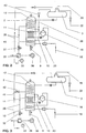
- the gas turbine / steam turbine combination system shown in FIG. 1 consists essentially of a gas turbine group, a trained as a condensation steam turbine steam consumer 1, a heat recovery steam generator arranged between the two 2 and a feed water tank 3 with integrated Feed water preheater / degasser 4.
- the gas turbine group sets Compressor 5, a gas turbine coupled to it 6, a combustion chamber 7 and a generator 8 together.
- the condensation steam turbine 1 can of course also other steam turbines or steam consumers 1 use Find.
- Heat recovery steam generators 2 are successive superheaters 10, an evaporator 11 and an economizer 12 are arranged.
- the Economizer 12 is on the input side via a feed water supply line 13 connected to the feed water tank 3.
- a feed water pump 14 is arranged in the Feed water supply line 13, a feed water pump 14 is arranged.
- the economizer 12 is on the output side via a water pipe 15 coupled to a steam drum 16.
- To the Steam drum 16 are the evaporator 11 and the superheater 10 connected, between the steam drum 16 and the evaporator 11 a circulation pump 17 is arranged.
- a live steam pipe 18 connects the superheater 10 to the condensing steam turbine 1, on the shaft of which a second generator 19 is arranged is.
- a live steam cooler 20 is located in the live steam line 18 trained and via a line 21 to the feed water supply 13 connected.
- the feed water preheater / degasser 4 is via a bleed line 22 to the condensation steam turbine 1 coupled.
- In the tap line 22 is a control / pressure reducing valve 23 arranged.
- the condensation steam turbine 1 is via an exhaust line 24 with a condenser 25 connected.
- the feed water preheater / degasser 4 is by means of a water pipe 26 in which a condensate pump 27 is arranged, connected to the capacitor 25.
- the one with an enlarged heat exchange surface Economizer 12 branches off a heating water line 28, which ends in the feed water tank 3.
- a preheater 29 is formed, which with one to one external consumer 30 leading heating water line 31 cooperates.
- An external consumer 30 is, for example District heating network connected to the heating water line 31.
- In the Heating water line 31 can be more, from the live steam line 18 or the condensation steam turbine 1 fed preheater be arranged (not shown).
- Upstream of the Preheater 29 is a control valve in the heating water line 28 32 and downstream of the preheater 29 a temperature measuring point 33 arranged. Both are via an evaluation, not shown Control unit connected to each other.
- the heating water pipe 28 contains a between the preheater 29 and the feed water tank 3 arranged pressure reducing valve 34.
- the compressor When the combination system is operating, the compressor sucks in 5 ambient air 35, compresses it and directs it into the Combustion chamber 7 continues. There fuel 36 is supplied with the compressed ambient air 35 mixed and that formed fuel-air mixture burned. The one when burning Smoke gases 37 formed are in the gas turbine 6 initiated and relaxed in it. Doing so at the same time the compressor arranged on a shaft with the gas turbine 6 5 and the generator 8 driven, the latter for the purpose Power generation.
- the relaxed, still hot flue gases 37 are in the heat recovery steam generator 2 initiated and there for the generation of Steam used for the condensation steam turbine 1. This will the flue gases 37 by heat exchange, with in counterflow the heat recovery steam generator 2 and out of the feed water tank 3 originating water, heat energy withdrawn. After that the flue gases 37 to the environment via a chimney 38 issued.
- the resulting, overheated steam is over the live steam line 18 of the condensation steam turbine 1 supplied, the steam temperature by injecting Water in the live steam cooler 20 is regulated.
- the hot one Steam is expanded in the condensation steam turbine 1, so that the generator 19 connected to it for power generation is driven.
- the temperature measuring point 33 i.e. downstream of the Preheater 29, constantly detects the temperature of the heating water.
- the evaluation connected to the temperature measuring point 33 and control unit determines when the external needs change Consumer 30 a temperature difference, which as Basis for a corresponding adjustment of the control valve 32 serves. This way it is exactly that of the external consumer 30 required amount of heating water from the economizer 12.
- This heating water is then the preheater 29 conducted, with most of its thermal energy to the heat transfer medium flowing through the heating water line 31 of the external consumer 30 transmitted becomes.
- the residual heat remaining in the heating water is via the Removed heating water line 28 and is used to heat the Feed water tank 3.
- the control valve 32 closed accordingly and thus a reduced Amount of heating water branched off via the heating water line 28.
- the one not required by the external consumer 30, i.e. released The amount of additional feed water is in the heat recovery steam generator 2 used for steam generation.
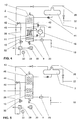
- a second embodiment differs from the first only in that a line 39 from the water line 15 branches off, which ends at the feed water tank 3 and a Control / pressure reducing valve 40 contains (Fig. 2).
- the evaluation and control unit determines a lower one than the maximum need of the external consumer 30, the remaining amount of the additional feed water becomes the branch of the heating water is further heated and then also branched off from the water / steam cycle. After that however, this remaining amount is divided into two Parts. A part, together with the actual feed water, used for steam generation and the other part about the line 39 is recirculated to the feed water tank 3. In order to the external consumer’s heat requirements decrease 30 for this unusable, additional amount of water, in addition of steam generation, also for preheating the feed water in the Feed water tank 3 used. That way it has to be about Tap line 22 less steam for heating the feed water tank 3 be dissipated so that the performance of the Condensation steam turbine 1 and thus the generation of electricity Generator 19 rises.
- the control valve 42 is with the above. Evaluation and control unit connected and is according to the heat demand of the external consumer 30 more or less opened or closed. This makes 30 for the external consumer not required, but already from the water / steam cycle branched amount of heating water directly to the feed water tank 3 fed.
- One of the leading from the Economizer 12 Water pipe 15 branching off and in the feed water tank 3 ending line 39 is in this embodiment not mandatory.
- the economizer 12, downstream of the branching of the heating water line 28, is connected via an additional water line 43 to a high-pressure feed water pump 44 arranged outside the heat recovery steam generator 2 (FIG. 4).
- a high-pressure feed water pump 44 arranged outside the heat recovery steam generator 2 (FIG. 4).
- This draws the preheated feed water downstream of the junction of the heating water required for the external consumer 30 from the economizer 12 and conveys it further downstream into a high-pressure economizer 45 arranged in the waste heat steam generator 2
- Feed water pump 14 designed as a low pressure feed water pump.
- the economizer 12 and the subsequent heating water line 28 are only supplied with the low-pressure water supplied by the low-pressure feed water pump 14.
Landscapes
- Engineering & Computer Science (AREA)
- Chemical & Material Sciences (AREA)
- Combustion & Propulsion (AREA)
- Mechanical Engineering (AREA)
- General Engineering & Computer Science (AREA)
- Engine Equipment That Uses Special Cycles (AREA)
Claims (6)
- Procédé d'exploitation d'un turbogroupe à gaz combiné avec un générateur de vapeur de récupération (2) monté en aval et un utilisateur de vapeur (1), en particulier une turbine à vapeur, pour une cogénération, le groupe de turbines à gaz étant constitué d'au moins un compresseur (5), une turbine à gaz (6), une chambre de combustion (7) ainsi qu'un générateur (8) et le générateur de vapeur de récupération (2) est raccordé à un réservoir d'eau d'alimentation (3), comprenant un préchauffeur/dégazeur d'eau d'alimentation (4), dans lequel :a) autant de l'eau d'alimentation pour le circuit d'eau/vapeur que de l'eau de chauffage supplémentaire pour un utilisateur de chaleur externe (30) sont introduites dans le générateur de vapeur à récupération (2) dans la zone de températures inférieure de ce dernier,b) l'eau de chauffage après chauffage est acheminée à l'utilisation externe ainsi qu'à une utilisation interne,
caractérisé en ce que :c) tout d'abord un débit d'eau d'alimentation augmenté du débit d'eau de chauffage nécessaire au maximum à l'utilisation externe est introduit dans le générateur de vapeur de récupération (2),d) ensuite, les besoins courants en eau de chauffage pour l'utilisation externe sont déterminés,e) après chauffage, on dérive un débit d'eau de chauffage correspondant aux besoins en eau de chauffage du débit supplémentaire d'eau d'alimentation à partir du circuit d'eau/vapeur, en cas d'absence de besoins en eau de chauffage, le débit supplémentaire d'eau d'alimentation reste dans le circuit d'eau/vapeur et est utilisé pour la production de vapeur supplémentaire,f) l'eau de chauffage dérivée est acheminée à l'utilisation externe et sa chaleur résiduaire est utilisée pour le chauffage du réservoir d'eau d'alimentation (3). - Procédé selon la revendication 1, caractérisé en ce que l'eau de chauffage dérivée est amenée tout d'abord en échange de chaleur avec un agent de transfert de chaleur de l'utilisateur de chaleur externe (30) et est ensuite transférée au réservoir d'eau d'alimentation (3).
- Procédé selon la revendication 2, caractérisé en ce que la détermination des besoins en chaleur de l'utilisateur de chaleur externe (30) se fait par une mesure permanente de la température de l'eau de chauffage après son échange de chaleur avec l'agent de transfert de chaleur de l'utilisateur externe (30) et la différence de température ainsi déterminée par rapport à la mesure antérieure est utilisée comme base pour une régulation correspondante du débit d'eau de chauffage à dériver du circuit d'eau/vapeur.
- Procédé selon l'une quelconque des revendications 1 à 3, caractérisé en ce que, tout d'abord, un débit d'eau de chauffage correspondant aux besoins en chaleur courants de l'utilisateur de chaleur externe (30) est dérivé du circuit eau/vapeur, le débit résiduaire de l'eau d'alimentation supplémentaire est réchauffé, ensuite il est dérivé également du circuit d'eau/vapeur, divisé en deux parties, une partie étant utilisée pour la production de vapeur et l'autre partie étant remise en circulation vers le réservoir d'eau d'alimentation (3).
- Procédé selon l'une quelconque des revendications 1 à 3, caractérisé en ce que le débit d'eau de chauffage qui n'est pas nécessité par l'utilisateur de chaleur externe (30), mais qui est déjà dérivé du circuit d'eau/vapeur est encore une fois dérivé avant échange de chaleur thermique est directement acheminé au réservoir d'eau d'alimentation (3).
- Procédé selon la revendication 5, caractérisé en ce que l'eau d'alimentation est tout d'abord introduite sous faible pression dans le circuit d'eau/vapeur, l'eau d'alimentation chauffée est extraite également du générateur de vapeur à récupération (2) après dérivation de l'eau de chauffage, elle y est à nouveau pompée ensuite sous pression élevée et est réchauffée avant son évaporation.
Applications Claiming Priority (2)
| Application Number | Priority Date | Filing Date | Title |
|---|---|---|---|
| DE19545668 | 1995-12-07 | ||
| DE19545668A DE19545668A1 (de) | 1995-12-07 | 1995-12-07 | Verfahren zum Betrieb einer mit einem Abhitzedampferzeuger und einem Dampfverbraucher kombinierten Gasturbogruppe |
Publications (3)
| Publication Number | Publication Date |
|---|---|
| EP0778397A2 EP0778397A2 (fr) | 1997-06-11 |
| EP0778397A3 EP0778397A3 (fr) | 1998-02-04 |
| EP0778397B1 true EP0778397B1 (fr) | 2003-02-05 |
Family
ID=7779450
Family Applications (1)
| Application Number | Title | Priority Date | Filing Date |
|---|---|---|---|
| EP96810770A Expired - Lifetime EP0778397B1 (fr) | 1995-12-07 | 1996-11-11 | Procédé d'opération d'une centrale combinée avec une chaudière de récuperation et un consommateur de vapeur |
Country Status (4)
| Country | Link |
|---|---|
| US (1) | US5799481A (fr) |
| EP (1) | EP0778397B1 (fr) |
| JP (1) | JP3883627B2 (fr) |
| DE (2) | DE19545668A1 (fr) |
Families Citing this family (33)
| Publication number | Priority date | Publication date | Assignee | Title |
|---|---|---|---|---|
| DE19720881A1 (de) * | 1997-05-17 | 1998-11-19 | Asea Brown Boveri | Kombikraftwerk mit Kraftwärmekopplung |
| DE19829088C2 (de) * | 1998-06-30 | 2002-12-05 | Man Turbomasch Ag Ghh Borsig | Stromerzeugung in einem Verbundkraftwerk mit einer Gas- und einer Dampfturbine |
| DE19944920B4 (de) * | 1999-09-20 | 2013-11-21 | Alstom Technology Ltd. | Kombikraftwerk mit Einspritzvorrichtung zum Einspritzen von Wasser in den Frischdampf |
| AU2003234207A1 (en) * | 2002-04-24 | 2003-11-10 | Randal C. Liprie | Cogeneration wasteheat evaporation system and method for wastewater treatment utilizing wasteheat recovery |
| GB0218740D0 (en) * | 2002-08-12 | 2002-09-18 | Bg Intellectual Pty Ltd | A wall mounted domestic combined heat and power appliance |
| JP4489756B2 (ja) * | 2003-01-22 | 2010-06-23 | ヴァスト・パワー・システムズ・インコーポレーテッド | エネルギー変換システム、エネルギー伝達システム、および熱伝達を制御する方法 |
| US8631657B2 (en) * | 2003-01-22 | 2014-01-21 | Vast Power Portfolio, Llc | Thermodynamic cycles with thermal diluent |
| US9254729B2 (en) * | 2003-01-22 | 2016-02-09 | Vast Power Portfolio, Llc | Partial load combustion cycles |
| US7284709B2 (en) * | 2003-11-07 | 2007-10-23 | Climate Energy, Llc | System and method for hydronic space heating with electrical power generation |
| US20050184167A1 (en) * | 2004-02-24 | 2005-08-25 | Stanley Bach | Heating, ventilating, and air-conditioning system utilizing a pressurized liquid and a fluid-turbine generator |
| JP2006009713A (ja) * | 2004-06-28 | 2006-01-12 | Hitachi Ltd | コージェネレーションシステム及びエネルギー供給システム |
| KR100579576B1 (ko) * | 2004-08-17 | 2006-05-15 | 엘지전자 주식회사 | 열병합 발전 시스템 |
| KR100600752B1 (ko) * | 2004-08-17 | 2006-07-14 | 엘지전자 주식회사 | 열병합 발전 시스템 |
| EA016385B1 (ru) * | 2007-03-22 | 2012-04-30 | Нутер/Эриксен, Инк. | Высокоэффективный нагреватель питательной воды |
| CN100540996C (zh) * | 2007-11-16 | 2009-09-16 | 冼泰来 | 蒸气回收仓 |
| US20100031933A1 (en) * | 2008-08-05 | 2010-02-11 | Prakash Narayan | System and assemblies for hot water extraction to pre-heat fuel in a combined cycle power plant |
| US8205451B2 (en) * | 2008-08-05 | 2012-06-26 | General Electric Company | System and assemblies for pre-heating fuel in a combined cycle power plant |
| US8186142B2 (en) * | 2008-08-05 | 2012-05-29 | General Electric Company | Systems and method for controlling stack temperature |
| US9435534B2 (en) * | 2009-08-31 | 2016-09-06 | Holistic Engineering Inc | Energy-recovery system for a production plant |
| SG182815A1 (en) * | 2010-02-09 | 2012-09-27 | Zibo Natergy Chemical Industry Co Ltd | Temperature differential engine device |
| DE102012218542B4 (de) * | 2012-10-11 | 2016-07-07 | Siemens Aktiengesellschaft | Verfahren zum flexiblen Betrieb einer Kraftwerksanlage |
| CN103216281B (zh) * | 2013-04-19 | 2014-12-10 | 国家电网公司 | 一种热电联产机组及其运行效率的评价方法 |
| CN104517238B (zh) * | 2013-09-28 | 2017-08-25 | 河北大唐国际丰润热电有限责任公司 | 热电联产机组智能能耗分析系统 |
| US10914200B2 (en) * | 2013-10-31 | 2021-02-09 | General Electric Technology Gmbh | Combined cycle power plant with improved efficiency |
| JP6044529B2 (ja) * | 2013-12-05 | 2016-12-14 | トヨタ自動車株式会社 | 廃熱回収装置 |
| EP2933556A1 (fr) * | 2014-04-14 | 2015-10-21 | Siemens Aktiengesellschaft | Préchauffage de condensat |
| CN104534539A (zh) * | 2015-01-08 | 2015-04-22 | 清华大学 | 一种燃气蒸汽联合循环集中供热装置及供热方法 |
| US20170356386A1 (en) * | 2016-06-13 | 2017-12-14 | Dana Limited | Integrated Internal Combustion Engine And Waste Heat Recovery System Including A Selective Catalytic Reduction Unit |
| CN109578967B (zh) * | 2019-01-24 | 2024-01-16 | 浙江杭振锅炉有限公司 | 一种燃气冷凝式蒸汽锅炉 |
| CN110631400B (zh) * | 2019-10-22 | 2020-12-01 | 大唐呼图壁能源开发有限公司热电厂 | 一种余热回收热电厂蓄能方法及装置 |
| CN111441745B (zh) * | 2020-05-08 | 2022-03-01 | 中国石油天然气股份有限公司 | 一种油田清蜡热洗设备及使用方法 |
| US11661857B2 (en) * | 2020-06-16 | 2023-05-30 | Cyrq Energy, Inc. | Electricity generating systems with thermal energy storage coupled superheaters |
| CN118653896A (zh) * | 2024-06-27 | 2024-09-17 | 西安热工研究院有限公司 | 一种多轴汽轮机及其使用方法 |
Family Cites Families (9)
| Publication number | Priority date | Publication date | Assignee | Title |
|---|---|---|---|---|
| DE1065666B (de) * | 1951-09-28 | 1959-09-17 | Power Jets (Research &. Development) Limited London | Kombinierte Gasturbmen-Dampferzeugungsanlage zur Lieferung sowohl von Wärmeenergie als auch mechanischer Leistung |
| DE2512774C2 (de) * | 1975-03-22 | 1982-09-02 | Brown, Boveri & Cie Ag, 6800 Mannheim | Kombinierte Gas-Dampfturbinenanlage |
| DE3225140A1 (de) * | 1982-07-06 | 1984-01-12 | Brown, Boveri & Cie Ag, 6800 Mannheim | Verfahren zum betreiben eines mit einer wirbelschichtfeuerung ausgeruesteten dampfkraftwerkes, insbesondere heizkraftwerkes |
| HU202958B (en) * | 1984-01-11 | 1991-04-29 | Energiagazdalkodasi Intezet | Method for combined electric power and heat producing at power plants operating with boilers of heat utilization |
| DE3524882C1 (de) * | 1985-07-12 | 1986-09-11 | Joachim 4600 Dortmund Schwieger | Verfahren zum Betreiben einer Heizkraftwerksanlage zur Fernwärme- und Stromerzeugung |
| FI75401C (fi) * | 1986-11-07 | 1988-06-09 | Ahlstroem Oy | Foerfarande foer tillvaratagande av vaerme i samband med en gasturbinprocess. |
| JPS6445908A (en) * | 1987-08-12 | 1989-02-20 | Hitachi Ltd | Heat and electricity feeding system |
| JPH01273936A (ja) * | 1988-04-25 | 1989-11-01 | Hitachi Ltd | 熱電併給プラントの温水利用冷暖房設備 |
| DE3841224A1 (de) * | 1988-12-07 | 1990-06-13 | Siemens Ag | Kombiniertes gasturbinen-dampfturbinen-kraftwerk |
-
1995
- 1995-12-07 DE DE19545668A patent/DE19545668A1/de not_active Withdrawn
-
1996
- 1996-11-11 DE DE59610114T patent/DE59610114D1/de not_active Expired - Lifetime
- 1996-11-11 EP EP96810770A patent/EP0778397B1/fr not_active Expired - Lifetime
- 1996-12-06 JP JP32721196A patent/JP3883627B2/ja not_active Expired - Lifetime
- 1996-12-06 US US08/761,390 patent/US5799481A/en not_active Expired - Lifetime
Also Published As
| Publication number | Publication date |
|---|---|
| JPH09177508A (ja) | 1997-07-08 |
| DE19545668A1 (de) | 1997-06-12 |
| EP0778397A2 (fr) | 1997-06-11 |
| US5799481A (en) | 1998-09-01 |
| EP0778397A3 (fr) | 1998-02-04 |
| DE59610114D1 (de) | 2003-03-13 |
| JP3883627B2 (ja) | 2007-02-21 |
Similar Documents
| Publication | Publication Date | Title |
|---|---|---|
| EP0778397B1 (fr) | Procédé d'opération d'une centrale combinée avec une chaudière de récuperation et un consommateur de vapeur | |
| EP0819209B1 (fr) | Procede de fonctionnement d'un generateur de vapeur a recuperation de chaleur, et generateur de vapeur a recuperation de chaleur fonctionnant selon ce procede | |
| EP2368021B1 (fr) | Générateur de vapeur à récupération de chaleur et procédé pour améliorer le fonctionnement d'un générateur de vapeur à récupération de chaleur | |
| EP0523467B1 (fr) | Procédé pour opérer une installation à turbines à gaz et à vapeur et installation pour la mise en oeuvre du procédé | |
| EP0526816B1 (fr) | Centrale à turbines à gaz et à vapeur avec un générateur de vapeur solaire | |
| EP0750718B1 (fr) | Procede permettant de faire fonctionner une installation a turbines a gaz et a vapeur et installation fonctionnant selon ledit procede | |
| DE102009036064B4 (de) | rfahren zum Betreiben eines mit einer Dampftemperatur von über 650°C operierenden Zwangdurchlaufdampferzeugers sowie Zwangdurchlaufdampferzeuger | |
| EP0591163B1 (fr) | Installation combinee a turbines a gaz et a vapeur | |
| EP0783619A1 (fr) | Procede permettant de faire fonctionner une installation a turbines a gaz et a vapeur, et installation fonctionnant selon ce procede | |
| WO1999019608A1 (fr) | Systeme de turbine a gaz et a vapeur et procede permettant de faire fonctionner un systeme de ce type | |
| EP0898641A1 (fr) | Installation a turbine a gaz et a turbine a vapeur et procede permettant de la faire fonctionner | |
| EP0523466B1 (fr) | Procédé de fonctionnement d'une installation à turbines à gaz et à vapeur et installation pour la mise en oeuvre du procédé | |
| EP0515911A1 (fr) | Méthode pour opérer une installation à turbines à gaz et à vapeur et une installation correspondante | |
| WO2000011325A1 (fr) | Installation de turbine a gaz et a vapeur | |
| EP0981681B1 (fr) | Systeme de turbines a gaz et a vapeur et procede de refroidissement de l'agent refrigerant de la turbine a gaz d'un tel systeme | |
| EP0840837B1 (fr) | Procede d'exploitation d'une installation de turbines a gaz et a vapeur et installation exploitee selon ce procede | |
| EP0410111B1 (fr) | Chaudière de récupération de chaleur pour une centrale à turbine à gaz et à vapeur | |
| WO2005056994A1 (fr) | Groupe moteur a reservoir d'air | |
| DE10155508C2 (de) | Verfahren und Vorrichtung zur Erzeugung von elektrischer Energie | |
| EP0586425B1 (fr) | Procede de generation d'energie dans une centrale thermique combinee a gaz et a vapeur | |
| DE4409811C1 (de) | Verfahren zum Betreiben eines Abhitzedampferzeugers sowie danach arbeitender Abhitzedampferzeuger | |
| EP0898054B1 (fr) | Générateur de vapeur et méthode d'exploitation | |
| EP1404947B1 (fr) | Procede pour faire fonctionner une installation motrice a vapeur et installation motrice a vapeur pour mettre en oeuvre ce procede | |
| DE19542917A1 (de) | Kombianlage mit konventionellem Wasser/Dampf-Kreislauf | |
| CH613255A5 (en) | System for the utilisation of waste heat from a gas flow to drive electrical generators |
Legal Events
| Date | Code | Title | Description |
|---|---|---|---|
| PUAI | Public reference made under article 153(3) epc to a published international application that has entered the european phase |
Free format text: ORIGINAL CODE: 0009012 |
|
| AK | Designated contracting states |
Kind code of ref document: A2 Designated state(s): DE FR GB NL |
|
| PUAL | Search report despatched |
Free format text: ORIGINAL CODE: 0009013 |
|
| AK | Designated contracting states |
Kind code of ref document: A3 Designated state(s): DE FR GB NL |
|
| 17P | Request for examination filed |
Effective date: 19980711 |
|
| 17Q | First examination report despatched |
Effective date: 20010528 |
|
| RAP1 | Party data changed (applicant data changed or rights of an application transferred) |
Owner name: ALSTOM |
|
| GRAG | Despatch of communication of intention to grant |
Free format text: ORIGINAL CODE: EPIDOS AGRA |
|
| GRAG | Despatch of communication of intention to grant |
Free format text: ORIGINAL CODE: EPIDOS AGRA |
|
| GRAG | Despatch of communication of intention to grant |
Free format text: ORIGINAL CODE: EPIDOS AGRA |
|
| GRAH | Despatch of communication of intention to grant a patent |
Free format text: ORIGINAL CODE: EPIDOS IGRA |
|
| GRAH | Despatch of communication of intention to grant a patent |
Free format text: ORIGINAL CODE: EPIDOS IGRA |
|
| RAP1 | Party data changed (applicant data changed or rights of an application transferred) |
Owner name: ALSTOM (SWITZERLAND) LTD |
|
| GRAA | (expected) grant |
Free format text: ORIGINAL CODE: 0009210 |
|
| AK | Designated contracting states |
Designated state(s): DE FR GB NL |
|
| PG25 | Lapsed in a contracting state [announced via postgrant information from national office to epo] |
Ref country code: NL Free format text: LAPSE BECAUSE OF FAILURE TO SUBMIT A TRANSLATION OF THE DESCRIPTION OR TO PAY THE FEE WITHIN THE PRESCRIBED TIME-LIMIT Effective date: 20030205 |
|
| REG | Reference to a national code |
Ref country code: GB Ref legal event code: FG4D Free format text: NOT ENGLISH |
|
| REF | Corresponds to: |
Ref document number: 59610114 Country of ref document: DE Date of ref document: 20030313 Kind code of ref document: P |
|
| GBT | Gb: translation of ep patent filed (gb section 77(6)(a)/1977) |
Effective date: 20030425 |
|
| NLV1 | Nl: lapsed or annulled due to failure to fulfill the requirements of art. 29p and 29m of the patents act | ||
| ET | Fr: translation filed | ||
| PLBE | No opposition filed within time limit |
Free format text: ORIGINAL CODE: 0009261 |
|
| STAA | Information on the status of an ep patent application or granted ep patent |
Free format text: STATUS: NO OPPOSITION FILED WITHIN TIME LIMIT |
|
| 26N | No opposition filed |
Effective date: 20031106 |
|
| REG | Reference to a national code |
Ref country code: DE Ref legal event code: R082 Ref document number: 59610114 Country of ref document: DE Representative=s name: UWE ROESLER, DE |
|
| REG | Reference to a national code |
Ref country code: GB Ref legal event code: 732E Free format text: REGISTERED BETWEEN 20120802 AND 20120808 |
|
| REG | Reference to a national code |
Ref country code: DE Ref legal event code: R082 Ref document number: 59610114 Country of ref document: DE Representative=s name: RUEGER, BARTHELT & ABEL, DE Effective date: 20120713 Ref country code: DE Ref legal event code: R082 Ref document number: 59610114 Country of ref document: DE Representative=s name: ROESLER, UWE, DIPL.-PHYS.UNIV., DE Effective date: 20120713 Ref country code: DE Ref legal event code: R081 Ref document number: 59610114 Country of ref document: DE Owner name: GENERAL ELECTRIC TECHNOLOGY GMBH, CH Free format text: FORMER OWNER: ALSTOM (SWITZERLAND) LTD., BADEN, CH Effective date: 20120713 Ref country code: DE Ref legal event code: R081 Ref document number: 59610114 Country of ref document: DE Owner name: ALSTOM TECHNOLOGY LTD., CH Free format text: FORMER OWNER: ALSTOM (SWITZERLAND) LTD., BADEN, CH Effective date: 20120713 |
|
| REG | Reference to a national code |
Ref country code: FR Ref legal event code: TP Owner name: ALSTOM TECHNOLOGY LTD., CH Effective date: 20120918 |
|
| REG | Reference to a national code |
Ref country code: FR Ref legal event code: PLFP Year of fee payment: 20 |
|
| PGFP | Annual fee paid to national office [announced via postgrant information from national office to epo] |
Ref country code: GB Payment date: 20151118 Year of fee payment: 20 Ref country code: DE Payment date: 20151119 Year of fee payment: 20 |
|
| PGFP | Annual fee paid to national office [announced via postgrant information from national office to epo] |
Ref country code: FR Payment date: 20151119 Year of fee payment: 20 |
|
| REG | Reference to a national code |
Ref country code: DE Ref legal event code: R082 Ref document number: 59610114 Country of ref document: DE Representative=s name: RUEGER ABEL PATENTANWAELTE PARTGMBB, DE Ref country code: DE Ref legal event code: R082 Ref document number: 59610114 Country of ref document: DE Representative=s name: RUEGER, BARTHELT & ABEL, DE |
|
| REG | Reference to a national code |
Ref country code: DE Ref legal event code: R082 Ref document number: 59610114 Country of ref document: DE Representative=s name: RUEGER, BARTHELT & ABEL, DE Ref country code: DE Ref legal event code: R081 Ref document number: 59610114 Country of ref document: DE Owner name: GENERAL ELECTRIC TECHNOLOGY GMBH, CH Free format text: FORMER OWNER: ALSTOM TECHNOLOGY LTD., BADEN, CH |
|
| REG | Reference to a national code |
Ref country code: DE Ref legal event code: R071 Ref document number: 59610114 Country of ref document: DE |
|
| REG | Reference to a national code |
Ref country code: GB Ref legal event code: PE20 Expiry date: 20161110 |
|
| REG | Reference to a national code |
Ref country code: FR Ref legal event code: CD Owner name: ALSTOM TECHNOLOGY LTD, CH Effective date: 20161124 |
|
| PG25 | Lapsed in a contracting state [announced via postgrant information from national office to epo] |
Ref country code: GB Free format text: LAPSE BECAUSE OF EXPIRATION OF PROTECTION Effective date: 20161110 |