EP0914548B1 - Abgaskrümmer für verbrennungsmotoren und verfahren zu seiner herstellung - Google Patents
Abgaskrümmer für verbrennungsmotoren und verfahren zu seiner herstellung Download PDFInfo
- Publication number
- EP0914548B1 EP0914548B1 EP98932045A EP98932045A EP0914548B1 EP 0914548 B1 EP0914548 B1 EP 0914548B1 EP 98932045 A EP98932045 A EP 98932045A EP 98932045 A EP98932045 A EP 98932045A EP 0914548 B1 EP0914548 B1 EP 0914548B1
- Authority
- EP
- European Patent Office
- Prior art keywords
- catalytic converter
- manifold
- exhaust manifold
- catalyst
- core
- Prior art date
- Legal status (The legal status is an assumption and is not a legal conclusion. Google has not performed a legal analysis and makes no representation as to the accuracy of the status listed.)
- Expired - Lifetime
Links
Images

Classifications
-
- F—MECHANICAL ENGINEERING; LIGHTING; HEATING; WEAPONS; BLASTING
- F01—MACHINES OR ENGINES IN GENERAL; ENGINE PLANTS IN GENERAL; STEAM ENGINES
- F01N—GAS-FLOW SILENCERS OR EXHAUST APPARATUS FOR MACHINES OR ENGINES IN GENERAL; GAS-FLOW SILENCERS OR EXHAUST APPARATUS FOR INTERNAL-COMBUSTION ENGINES
- F01N13/00—Exhaust or silencing apparatus characterised by constructional features
- F01N13/08—Other arrangements or adaptations of exhaust conduits
- F01N13/10—Other arrangements or adaptations of exhaust conduits of exhaust manifolds
-
- F—MECHANICAL ENGINEERING; LIGHTING; HEATING; WEAPONS; BLASTING
- F01—MACHINES OR ENGINES IN GENERAL; ENGINE PLANTS IN GENERAL; STEAM ENGINES
- F01N—GAS-FLOW SILENCERS OR EXHAUST APPARATUS FOR MACHINES OR ENGINES IN GENERAL; GAS-FLOW SILENCERS OR EXHAUST APPARATUS FOR INTERNAL-COMBUSTION ENGINES
- F01N3/00—Exhaust or silencing apparatus having means for purifying, rendering innocuous, or otherwise treating exhaust
- F01N3/08—Exhaust or silencing apparatus having means for purifying, rendering innocuous, or otherwise treating exhaust for rendering innocuous
- F01N3/10—Exhaust or silencing apparatus having means for purifying, rendering innocuous, or otherwise treating exhaust for rendering innocuous by thermal or catalytic conversion of noxious components of exhaust
- F01N3/24—Exhaust or silencing apparatus having means for purifying, rendering innocuous, or otherwise treating exhaust for rendering innocuous by thermal or catalytic conversion of noxious components of exhaust characterised by constructional aspects of converting apparatus
- F01N3/28—Construction of catalytic reactors
- F01N3/2839—Arrangements for mounting catalyst support in housing, e.g. with means for compensating thermal expansion or vibration
- F01N3/2853—Arrangements for mounting catalyst support in housing, e.g. with means for compensating thermal expansion or vibration using mats or gaskets between catalyst body and housing
- F01N3/2857—Arrangements for mounting catalyst support in housing, e.g. with means for compensating thermal expansion or vibration using mats or gaskets between catalyst body and housing the mats or gaskets being at least partially made of intumescent material, e.g. unexpanded vermiculite
Definitions
- the invention relates to an exhaust manifold for internal combustion engines, consisting of at least one manifold pipe with its End flanges arranged and with one in a straight, extended section of the manifold pipe arranged Catalyst.
- the invention also relates to a casting core and a method of manufacturing the exhaust manifold.
- the exhaust gas from gasoline or diesel engines contains substances such as HC, CO, No x and other environmentally harmful components.
- the emission of these pollutants must be kept as low as possible. Particularly high emissions are released into the atmosphere during the start-up and warm-up phases, since the combustion in the engine cylinders is still incomplete during the start-up and cold-running phases. In this cold-running phase, the substances HC, CO and other particles are still contained in the exhaust gases in high concentrations.
- catalysts are almost always arranged in the exhaust pipe connected to the engine on the exhaust gas, the task of which is to convert the pollutants into neutral components.
- EP-A-761 939 discloses an exhaust manifold catalyst arrangement where the manifold and parts of the adjacent catalyst housing are cast in one piece.
- the catalyst substrate With catalytic effective ingredients used.
- Via a separate, end part closing the catalytic converter housing with connecting flange is the manifold-catalytic converter assembly with a further exhaust pipe can be connected.
- the invention is based, while maintaining the task an arrangement of catalysts as close as possible to the cylinder head an exhaust manifold and a suitable manufacturing process to create that can be produced with reasonable effort and the outside except the connection flanges for the cylinder head and the advanced exhaust pipe from projecting, space-consuming Fasteners is free.
- exhaust manifold or "manifold pipe” is the part of entire exhaust system flanged to the engine to understand the connection between the engine or cylinder head and the Exhaust pipe leading exhaust pipe forms, the manifold depending on the number of cylinders corresponding branch line pieces having.
- a flange and screw connection of the otherwise usually arranged in a separate housing catalyst on the exhaust manifold is omitted because the catalyst according to the invention in the exhaust manifold is cast in and with this an integral Building unit forms, i.e., because all and ultimately additional assembly work and space-requiring flange connections is also a compact, which is usually eliminated in modern vehicles, confined spaces in the engine compartment appropriate accommodation of the containing the catalyst Exhaust manifold allows only the connection to the cylinder head of the engine in question.
- the catalyst suffers from its catalytically active Coating, as has been shown and as mentioned, by the heat entered by molten cast iron no damage, and also an undesirable loss of efficiency of the cat could not be determined.
- By rapidly cooling the melt given the small wall thickness, neither washcoat nor Catalytic noble metal entry on the catalyst is negatively affected.
- After machining the manifold flanges is the Exhaust manifold with cast-in integrated catalytic converter ready for installation. It can easily be wound metal catalysts or catalysts in the form of ceramic monoliths be cast around.
- Another advantage of the invention is the "self-adaptation" the liquid melt at the usually tolerances having catalyst.
- the circumference of the cast Catalyst result thanks to the cast integration the same radial stresses everywhere, regardless of whether there are any geometrical deviations such as out-of-roundness, taper or other shape defects available.
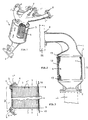
- the exhaust manifold for internal combustion engines as an exemplary embodiment is still shown at least one manifold pipe 1 arranged at its ends Connection flanges 2 and with one in a straight, expanded Section 3 of the manifold pipe 1 arranged catalyst 4.
- Fig. 1, 2 is for such an exhaust manifold now essential that the catalyst 4 as a "lost core" in straight section 3 of the manifold pipe cast in one piece 1 is arranged, i.e. the entire exhaust manifold with its in 1, for example, only shows an outer shape including the catalyst integral unit that Ready for installation with their top four branch line connections 2 on the cylinder head ZK of an otherwise not shown four-cylinder engine flanged in a conventional manner and to the lower, leading to the muffler (also not shown) Exhaust pipe AL is connected.
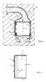
- Fig. 6 C is the "Total core” according to the invention in its preferred embodiment also shown, i.e. the two connections or Manifold cores 8,8 'are in their attachment areas to Catalyst 4 provided with circumferential beads 9 that the joints between the manifold cores and the end faces 5 and thus the Cover foils 7.
- foils 7, which consist, for example, of suitable paper, on the end faces 5,5 'of the catalyst 4 for the fact that in no case core sand from those to be placed on the front Manifold cores 8,8 'due to unfavorable circumstances Kat coating in the flow channels 4 '(only schematically in Figure 3 indicated) can reach the catalyst 4, the Powder filling in the channels 4 'on the one hand for support of the two thin protective films 7 and on the other hand for this ensures that no film remains in their "burning away" during the Gusses get into the flow channels 4 ', which the catalyst effect would affect.
- the catalyst 4 is ceramic acts, this is advantageous with a so-called inflatable mat 12 (e.g. fleece made of refractory fibers with embedded vermiculite particles) envelops, which swells when heated and the ceramic monoliths forming the catalyst safely in the cast Exhaust manifold fixed. Also painting the ceramic monolith with so-called slip can be considered become.
- an inflatable mat 12 it is required, as also indicated in Fig. 3, after cover the top and bottom with so-called fade protection rings 13. To further move such an inflatable mat 12 To prevent the casting process, this can be done with the outer surface of the catalyst 4 glued and / or with a winding thin wire 14 (see Fig. 4) can be fixed.
Landscapes
- Engineering & Computer Science (AREA)
- Chemical & Material Sciences (AREA)
- Chemical Kinetics & Catalysis (AREA)
- Mechanical Engineering (AREA)
- General Engineering & Computer Science (AREA)
- Combustion & Propulsion (AREA)
- Toxicology (AREA)
- Health & Medical Sciences (AREA)
- Exhaust Gas After Treatment (AREA)
- Exhaust Silencers (AREA)
- Organic Low-Molecular-Weight Compounds And Preparation Thereof (AREA)
- Cylinder Crankcases Of Internal Combustion Engines (AREA)
- Exhaust-Gas Circulating Devices (AREA)
Applications Claiming Priority (3)
| Application Number | Priority Date | Filing Date | Title |
|---|---|---|---|
| DE19718853A DE19718853A1 (de) | 1997-05-03 | 1997-05-03 | Abgaskrümmer für Verbrennungsmotoren und Verfahren zu seiner Herstellung |
| DE19718853 | 1997-05-03 | ||
| PCT/DE1998/001213 WO1998050687A1 (de) | 1997-05-03 | 1998-05-01 | Abgaskrümmer für verbrennungsmotoren und verfahren zu seiner herstellung |
Publications (2)
| Publication Number | Publication Date |
|---|---|
| EP0914548A1 EP0914548A1 (de) | 1999-05-12 |
| EP0914548B1 true EP0914548B1 (de) | 2002-07-31 |
Family
ID=7828615
Family Applications (1)
| Application Number | Title | Priority Date | Filing Date |
|---|---|---|---|
| EP98932045A Expired - Lifetime EP0914548B1 (de) | 1997-05-03 | 1998-05-01 | Abgaskrümmer für verbrennungsmotoren und verfahren zu seiner herstellung |
Country Status (6)
| Country | Link |
|---|---|
| EP (1) | EP0914548B1 (pl) |
| AT (1) | ATE221615T1 (pl) |
| DE (2) | DE19718853A1 (pl) |
| PL (1) | PL193602B1 (pl) |
| SK (1) | SK181198A3 (pl) |
| WO (1) | WO1998050687A1 (pl) |
Families Citing this family (9)
| Publication number | Priority date | Publication date | Assignee | Title |
|---|---|---|---|---|
| KR100309839B1 (ko) * | 1999-07-15 | 2001-11-01 | 이계안 | 차량용 배기가스의 후처리 장치 |
| DE10145876A1 (de) * | 2001-09-18 | 2003-04-10 | Daimler Chrysler Ag | Vorrichtung zur Herstellung eines Druckgussbauteils mit einem Kern und einem Einlegeteil |
| DE10159158A1 (de) * | 2001-12-01 | 2003-06-18 | Deutz Ag | Abgassammeldämpfer mit integriertem Abgasnachbehandlungssystem |
| AU2002346693A1 (en) * | 2001-12-07 | 2003-06-23 | Dan T. Moore Company | Insulated exhaust manifold having internal catalyst support body |
| US6725656B2 (en) | 2001-12-07 | 2004-04-27 | Dan T. Moore Company | Insulated exhaust manifold |
| DE20302615U1 (de) * | 2003-02-17 | 2004-07-15 | Tower Automotive Gmbh & Co. Kg | Hohlformteil mit geschlossenem Querschnitt und einer Verstärkung |
| DE102004018693B4 (de) * | 2004-04-17 | 2007-09-06 | Daimlerchrysler Ag | Abgasanlage |
| EP3190279B1 (en) * | 2014-09-03 | 2019-05-08 | Nissan Motor Co., Ltd | Exhaust device for internal combustion engine |
| CN109296435B (zh) * | 2018-09-06 | 2024-07-05 | 中国第一汽车股份有限公司 | 一种改善发动机冷态启动排放的排气歧管结构 |
Family Cites Families (3)
| Publication number | Priority date | Publication date | Assignee | Title |
|---|---|---|---|---|
| SE453968B (sv) * | 1985-02-01 | 1988-03-21 | Kanthal Ab | Gjuten metallkropp och sett att framstella densamma |
| JPH05140700A (ja) * | 1991-11-15 | 1993-06-08 | Mazda Motor Corp | フエライト系耐熱鋳鋼部材及びその製造法 |
| EP0761939A1 (en) * | 1995-08-16 | 1997-03-12 | General Motors Corporation | Manifold converter |
-
1997
- 1997-05-03 DE DE19718853A patent/DE19718853A1/de not_active Withdrawn
-
1998
- 1998-05-01 SK SK1811-98A patent/SK181198A3/sk unknown
- 1998-05-01 WO PCT/DE1998/001213 patent/WO1998050687A1/de not_active Ceased
- 1998-05-01 DE DE59804978T patent/DE59804978D1/de not_active Expired - Lifetime
- 1998-05-01 AT AT98932045T patent/ATE221615T1/de not_active IP Right Cessation
- 1998-05-01 PL PL98330715A patent/PL193602B1/pl not_active IP Right Cessation
- 1998-05-01 EP EP98932045A patent/EP0914548B1/de not_active Expired - Lifetime
Also Published As
| Publication number | Publication date |
|---|---|
| ATE221615T1 (de) | 2002-08-15 |
| SK181198A3 (en) | 1999-05-07 |
| EP0914548A1 (de) | 1999-05-12 |
| WO1998050687A1 (de) | 1998-11-12 |
| DE19718853A1 (de) | 1998-11-05 |
| PL193602B1 (pl) | 2007-02-28 |
| DE59804978D1 (de) | 2002-09-05 |
| PL330715A1 (en) | 1999-05-24 |
Similar Documents
| Publication | Publication Date | Title |
|---|---|---|
| DE2537676C2 (de) | Wärmeisolierende Auskleidung einer Brennkraftmaschine | |
| DE69026445T2 (de) | Abgasreinigungsvorrichtung für Brennkraftmaschinen | |
| DE69513092T2 (de) | Ein Verfahren zur Anwendung eines Schalldämpfers und eine Vorrichtung zur Anwendung des Verfahrens in einem grossen Dieselmotor | |
| EP1047865B1 (de) | Wabenkörperanordnung mit einer mindestens eine metallfolie enthaltenden zwischenschicht | |
| EP0914548B1 (de) | Abgaskrümmer für verbrennungsmotoren und verfahren zu seiner herstellung | |
| DE2233907A1 (de) | Reaktoranlage zur reinigung von aus verbrennungskraftmaschinen austretendem gas | |
| DE2303034C3 (de) | Nachverbrennungsvorrichtung für die Abgase von Brennkraftmaschinen | |
| EP0928885B1 (de) | Abgasvorrichtung für einen Verbrennungsmotor | |
| DE2354254A1 (de) | Verfahren zur herstellung eines waermeisolierenden gusserzeugnisses | |
| EP0778918B1 (de) | Katalytischer reaktor | |
| EP0220371B1 (de) | Verfahren zur Herstellung eines Heissgasführungsbauteils, insbesondere Abgasführungsbauteils für Verbrennungsmotore | |
| DE2222663A1 (de) | Verfahren zur herstellung einer vorrichtung zur katalytischen reinigung der auspuffgase von brennkraftmaschinen | |
| DE2850816A1 (de) | Brennkraftmaschine | |
| EP0205895A1 (de) | Abgasleitung einer Brennkraftmaschine | |
| DE2434102A1 (de) | Katalysator zur katalytischen reinigung von abgasen | |
| WO1999040300A1 (de) | Katalytische abgasreinigungseinrichtung und zugehörige ausgleichsschicht, insbesondere für kraftfahrzeuge | |
| DE19646025A1 (de) | Heizungsanordnung für einen Katalysator | |
| DE2848110A1 (de) | Auspuffleitung fuer verbrennungskraftmaschinen | |
| DE2555166A1 (de) | Zylinderkopf | |
| DE8019814U1 (de) | Vorrichtung zur lagerung von katalysatorbloecken zur abgasreinigung in auspuffanlagen fuer verbrennungsmotoren | |
| DE10357125A1 (de) | Krümmer für eine Abgasanlage und Verfahren zur Herstellung eines Krümmers | |
| DE19755703B4 (de) | Katalysatorträgeranordnung für einen motornahen Einbau | |
| DE2549255A1 (de) | Katalytische reinigungsanlage fuer die abgase von brennkraftmaschinen | |
| DE3100939A1 (de) | Katalytische reinigungseinheit fuer abgase von verbrennungsmotoren und verfahren zu ihrer herstellung | |
| DE2617938A1 (de) | Zylinderkopf und verfahren zu seiner herstellung |
Legal Events
| Date | Code | Title | Description |
|---|---|---|---|
| PUAI | Public reference made under article 153(3) epc to a published international application that has entered the european phase |
Free format text: ORIGINAL CODE: 0009012 |
|
| 17P | Request for examination filed |
Effective date: 19990107 |
|
| AK | Designated contracting states |
Kind code of ref document: A1 Designated state(s): AT BE CH DE DK ES FI FR GB IE IT LI NL PT SE |
|
| 17Q | First examination report despatched |
Effective date: 20000623 |
|
| GRAG | Despatch of communication of intention to grant |
Free format text: ORIGINAL CODE: EPIDOS AGRA |
|
| GRAG | Despatch of communication of intention to grant |
Free format text: ORIGINAL CODE: EPIDOS AGRA |
|
| GRAH | Despatch of communication of intention to grant a patent |
Free format text: ORIGINAL CODE: EPIDOS IGRA |
|
| GRAH | Despatch of communication of intention to grant a patent |
Free format text: ORIGINAL CODE: EPIDOS IGRA |
|
| RAP1 | Party data changed (applicant data changed or rights of an application transferred) |
Owner name: EMITEC GESELLSCHAFT FUER EMISSIONSTECHNOLOGIE MBH |
|
| GRAA | (expected) grant |
Free format text: ORIGINAL CODE: 0009210 |
|
| AK | Designated contracting states |
Kind code of ref document: B1 Designated state(s): AT BE CH DE DK ES FI FR GB IE IT LI NL PT SE |
|
| PG25 | Lapsed in a contracting state [announced via postgrant information from national office to epo] |
Ref country code: NL Free format text: LAPSE BECAUSE OF FAILURE TO SUBMIT A TRANSLATION OF THE DESCRIPTION OR TO PAY THE FEE WITHIN THE PRESCRIBED TIME-LIMIT Effective date: 20020731 Ref country code: IE Free format text: LAPSE BECAUSE OF FAILURE TO SUBMIT A TRANSLATION OF THE DESCRIPTION OR TO PAY THE FEE WITHIN THE PRESCRIBED TIME-LIMIT Effective date: 20020731 Ref country code: FI Free format text: LAPSE BECAUSE OF FAILURE TO SUBMIT A TRANSLATION OF THE DESCRIPTION OR TO PAY THE FEE WITHIN THE PRESCRIBED TIME-LIMIT Effective date: 20020731 |
|
| REF | Corresponds to: |
Ref document number: 221615 Country of ref document: AT Date of ref document: 20020815 Kind code of ref document: T |
|
| REG | Reference to a national code |
Ref country code: GB Ref legal event code: FG4D Free format text: NOT ENGLISH Ref country code: CH Ref legal event code: EP |
|
| REG | Reference to a national code |
Ref country code: IE Ref legal event code: FG4D Free format text: GERMAN |
|
| REF | Corresponds to: |
Ref document number: 59804978 Country of ref document: DE Date of ref document: 20020905 |
|
| PG25 | Lapsed in a contracting state [announced via postgrant information from national office to epo] |
Ref country code: DK Free format text: LAPSE BECAUSE OF FAILURE TO SUBMIT A TRANSLATION OF THE DESCRIPTION OR TO PAY THE FEE WITHIN THE PRESCRIBED TIME-LIMIT Effective date: 20021031 |
|
| PG25 | Lapsed in a contracting state [announced via postgrant information from national office to epo] |
Ref country code: PT Free format text: LAPSE BECAUSE OF FAILURE TO SUBMIT A TRANSLATION OF THE DESCRIPTION OR TO PAY THE FEE WITHIN THE PRESCRIBED TIME-LIMIT Effective date: 20021114 |
|
| GBT | Gb: translation of ep patent filed (gb section 77(6)(a)/1977) |
Effective date: 20021106 |
|
| NLV1 | Nl: lapsed or annulled due to failure to fulfill the requirements of art. 29p and 29m of the patents act | ||
| PG25 | Lapsed in a contracting state [announced via postgrant information from national office to epo] |
Ref country code: ES Free format text: LAPSE BECAUSE OF FAILURE TO SUBMIT A TRANSLATION OF THE DESCRIPTION OR TO PAY THE FEE WITHIN THE PRESCRIBED TIME-LIMIT Effective date: 20030130 |
|
| ET | Fr: translation filed | ||
| REG | Reference to a national code |
Ref country code: IE Ref legal event code: FD4D Ref document number: 0914548E Country of ref document: IE |
|
| PG25 | Lapsed in a contracting state [announced via postgrant information from national office to epo] |
Ref country code: AT Free format text: LAPSE BECAUSE OF NON-PAYMENT OF DUE FEES Effective date: 20030501 |
|
| PG25 | Lapsed in a contracting state [announced via postgrant information from national office to epo] |
Ref country code: LI Free format text: LAPSE BECAUSE OF NON-PAYMENT OF DUE FEES Effective date: 20030531 Ref country code: CH Free format text: LAPSE BECAUSE OF NON-PAYMENT OF DUE FEES Effective date: 20030531 Ref country code: BE Free format text: LAPSE BECAUSE OF NON-PAYMENT OF DUE FEES Effective date: 20030531 |
|
| PLBE | No opposition filed within time limit |
Free format text: ORIGINAL CODE: 0009261 |
|
| STAA | Information on the status of an ep patent application or granted ep patent |
Free format text: STATUS: NO OPPOSITION FILED WITHIN TIME LIMIT |
|
| 26N | No opposition filed |
Effective date: 20030506 |
|
| BERE | Be: lapsed |
Owner name: *EMITEC G.- FUR EMISSIONSTECHNOLOGIE M.B.H. Effective date: 20030531 |
|
| REG | Reference to a national code |
Ref country code: CH Ref legal event code: PL |
|
| PGFP | Annual fee paid to national office [announced via postgrant information from national office to epo] |
Ref country code: DE Payment date: 20120625 Year of fee payment: 15 |
|
| PGFP | Annual fee paid to national office [announced via postgrant information from national office to epo] |
Ref country code: GB Payment date: 20120523 Year of fee payment: 15 Ref country code: FR Payment date: 20120614 Year of fee payment: 15 Ref country code: SE Payment date: 20120523 Year of fee payment: 15 |
|
| PGFP | Annual fee paid to national office [announced via postgrant information from national office to epo] |
Ref country code: IT Payment date: 20120521 Year of fee payment: 15 |
|
| REG | Reference to a national code |
Ref country code: SE Ref legal event code: EUG |
|
| GBPC | Gb: european patent ceased through non-payment of renewal fee |
Effective date: 20130501 |
|
| PG25 | Lapsed in a contracting state [announced via postgrant information from national office to epo] |
Ref country code: SE Free format text: LAPSE BECAUSE OF NON-PAYMENT OF DUE FEES Effective date: 20130502 Ref country code: DE Free format text: LAPSE BECAUSE OF NON-PAYMENT OF DUE FEES Effective date: 20131203 |
|
| REG | Reference to a national code |
Ref country code: DE Ref legal event code: R119 Ref document number: 59804978 Country of ref document: DE Effective date: 20131203 |
|
| PG25 | Lapsed in a contracting state [announced via postgrant information from national office to epo] |
Ref country code: IT Free format text: LAPSE BECAUSE OF NON-PAYMENT OF DUE FEES Effective date: 20130501 |
|
| REG | Reference to a national code |
Ref country code: FR Ref legal event code: ST Effective date: 20140131 |
|
| PG25 | Lapsed in a contracting state [announced via postgrant information from national office to epo] |
Ref country code: GB Free format text: LAPSE BECAUSE OF NON-PAYMENT OF DUE FEES Effective date: 20130501 |
|
| PG25 | Lapsed in a contracting state [announced via postgrant information from national office to epo] |
Ref country code: FR Free format text: LAPSE BECAUSE OF NON-PAYMENT OF DUE FEES Effective date: 20130531 |