EP0913313B1 - Lenkrad mit einem Lenkradtopf - Google Patents
Lenkrad mit einem Lenkradtopf Download PDFInfo
- Publication number
- EP0913313B1 EP0913313B1 EP98119460A EP98119460A EP0913313B1 EP 0913313 B1 EP0913313 B1 EP 0913313B1 EP 98119460 A EP98119460 A EP 98119460A EP 98119460 A EP98119460 A EP 98119460A EP 0913313 B1 EP0913313 B1 EP 0913313B1
- Authority
- EP
- European Patent Office
- Prior art keywords
- steering wheel
- plate
- base
- hollow
- airbag
- Prior art date
- Legal status (The legal status is an assumption and is not a legal conclusion. Google has not performed a legal analysis and makes no representation as to the accuracy of the status listed.)
- Expired - Lifetime
Links
- 101100298222 Caenorhabditis elegans pot-1 gene Proteins 0.000 description 4
- 238000006073 displacement reaction Methods 0.000 description 3
- 230000001960 triggered effect Effects 0.000 description 3
- 230000007246 mechanism Effects 0.000 description 2
- 230000000149 penetrating effect Effects 0.000 description 2
- 230000006378 damage Effects 0.000 description 1
- 230000006735 deficit Effects 0.000 description 1
- 238000004519 manufacturing process Methods 0.000 description 1
- 238000000034 method Methods 0.000 description 1
- 230000001681 protective effect Effects 0.000 description 1
Images

Classifications
-
- B—PERFORMING OPERATIONS; TRANSPORTING
- B60—VEHICLES IN GENERAL
- B60R—VEHICLES, VEHICLE FITTINGS, OR VEHICLE PARTS, NOT OTHERWISE PROVIDED FOR
- B60R21/00—Arrangements or fittings on vehicles for protecting or preventing injuries to occupants or pedestrians in case of accidents or other traffic risks
- B60R21/02—Occupant safety arrangements or fittings, e.g. crash pads
- B60R21/16—Inflatable occupant restraints or confinements designed to inflate upon impact or impending impact, e.g. air bags
- B60R21/20—Arrangements for storing inflatable members in their non-use or deflated condition; Arrangement or mounting of air bag modules or components
- B60R21/203—Arrangements for storing inflatable members in their non-use or deflated condition; Arrangement or mounting of air bag modules or components in steering wheels or steering columns
-
- B—PERFORMING OPERATIONS; TRANSPORTING
- B62—LAND VEHICLES FOR TRAVELLING OTHERWISE THAN ON RAILS
- B62D—MOTOR VEHICLES; TRAILERS
- B62D1/00—Steering controls, i.e. means for initiating a change of direction of the vehicle
- B62D1/02—Steering controls, i.e. means for initiating a change of direction of the vehicle vehicle-mounted
- B62D1/04—Hand wheels
- B62D1/11—Hand wheels incorporating energy-absorbing arrangements, e.g. by being yieldable or collapsible
-
- B—PERFORMING OPERATIONS; TRANSPORTING
- B60—VEHICLES IN GENERAL
- B60R—VEHICLES, VEHICLE FITTINGS, OR VEHICLE PARTS, NOT OTHERWISE PROVIDED FOR
- B60R21/00—Arrangements or fittings on vehicles for protecting or preventing injuries to occupants or pedestrians in case of accidents or other traffic risks
- B60R21/02—Occupant safety arrangements or fittings, e.g. crash pads
- B60R21/16—Inflatable occupant restraints or confinements designed to inflate upon impact or impending impact, e.g. air bags
- B60R21/20—Arrangements for storing inflatable members in their non-use or deflated condition; Arrangement or mounting of air bag modules or components
- B60R21/217—Inflation fluid source retainers, e.g. reaction canisters; Connection of bags, covers, diffusers or inflation fluid sources therewith or together
- B60R2021/2173—Inflation fluid source retainers, e.g. reaction canisters; Connection of bags, covers, diffusers or inflation fluid sources therewith or together the module or part thereof being movably mounted on the vehicle
Definitions
- the invention relates to a steering wheel with a steering wheel pot, which is attached with its bottom on a steering column and in which one inflates in the event of a vehicle crash Airbag is housed and from its outer surface Spokes to one opposite the steering wheel pot axially to the vehicle interior lead staggered steering wheel rim, the Airbag on one at rest against the bottom of the steering wheel pot adjacent, when inflating the airbag inside of the steering wheel pot shifting away from the floor Plate is attached, which stroke limitation means for the maximum possible stroke of the plate relative to the ground.
- a steering wheel of the above type is the subject of the US 4,943,027.
- the airbag arranged in the steering wheel pot should be fully inflated in the event of a crash, if the driver is thrown in the direction of the steering wheel to prevent a hard impact on the steering wheel.
- According to the aforementioned US 4,943,027 shifts when the Airbag the plate with the airbag from the bottom of the steering wheel away towards the vehicle interior.
- the airbag cannot be moved connected to the bottom of the steering wheel. In both cases it can occur that the protective effect of the airbag does not occur. This is the case, for example, when you are with a Accident first on a first obstacle and then against one further, finally bringing the vehicle to a standstill Obstacle bounces.
- the airbag will in such a case inflated on the first impact and can continue until the second Impact should be empty again.
- the case that it is too close to the Steering wheel sits and against the still inflating airbag bounces, which is then undesirably hard and unyielding at first is. It would therefore be desirable if the steering wheel were in the axial direction is deformable to be independent of the airbag at a Impact of the driver against the steering wheel in the axial direction to give in.
- the invention is based on the problem of a steering wheel with a To shape the airbag in his steering wheel pot so that it is deformable in the axial direction.
- This design of the steering wheel creates after triggering of the airbag in the steering wheel pot a free space. This can in the event of an impact of the driver against the steering wheel rim dodge forward by pulling the ends of the spokes move into this free space of the steering wheel pot.
- a steering wheel which has the consequences of an impact regardless of the airbag through its axial deformability too mitigate. Furthermore, this deformability in the event of an accident, the freedom for the driver is increased, so the risk of getting caught behind the Steering wheel becomes lower.
- the training according to the invention the steering wheel is much cheaper than the previously announced withdrawal measures the steering wheel in the event of a frontal impact, so that the passive security of Motor vehicles can be increased.
- the plate After the airbag is triggered, the plate is in its Movement away from the bottom of the steering wheel pot does not suddenly occur slowed down, causing destruction of components and the plate is released could, if according to a very particularly advantageous Development of the invention of the head of the bolt of the shaft of which has a conical surface in cross section extended.
- the conical surface slightly widen the recess, before the head of the bolt another axial Path no longer allows. There is therefore a braking via a path defined by the conical surfaces and not a sudden attack.
- the steering wheel has two stroke limiting means. In order to let them inflate the airbag forces occurring particularly well and evenly from that Catch the bottom of the steering wheel pot.
- a jamming of the bolts in the holes and thus one Impairment of the axial stroke of the plate when triggered of the airbag can be done easily exclude that the plate in the pot by an anti-rotation is guided and the bolts in the Recesses in the bottom of the steering wheel pot through the maximum possible rotation of the plate cannot be canceled Have play.
- the spokes and the steering wheel pot can be very different be designed to avoid evasion to reach the ends of the spokes into the steering wheel pot. It would be possible, for example, the outer surface of the Steering wheel pot so deformable that the In the event of an accident, spoke with areas of the steering wheel pot in the space behind the plate and the floor of the Move the steering wheel pot into it. It is particularly easy Steering wheel designed when the spokes are on their the Steering column facing side one to the side of the Steering column facing and up against Outer lateral surface of the web leading the steering wheel pot have and the steering wheel pot in his coat in the area Provide each web with a predetermined breaking area is. As a result, the ends of the Spokes into the steering wheel pot.
- Steering wheels are often used during normal operation of the motor vehicle stressed with high forces. Often forms steering wheels so stable that the driver gets his full Can support weight on the steering wheel without this deformed in the process. Even with a steering wheel with predetermined breaking points you can provide this high strength if the Crosspieces in the axial direction of the steering wheel pot over the in Steering wheel pot arranged, in the idle state Plate. This configuration prevents When the plate is at rest, the spokes buckle into the Steering wheel pot by placing the areas behind the predetermined breaking points supported. This support works in the event of an accident lost when the plate is facing the driver moved, so that the predetermined breaking points are already at relative low forces can break and the desired axial displacement of the steering wheel occurs.
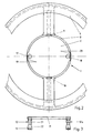
- Figure 1 shows one on a not shown Steering column to be attached steering wheel pot 1, which one Bottom 2 and a coat 3 has. Lead from the jacket 3 Spokes 4, 5 to form a steering wheel rim 6. These spokes 4, 5 each have on the side facing away from the driver a web 7, 8, which is connected to the jacket 3. in the The area of this connection has the jacket 3 in each case a predetermined breaking area 9 generated by a recess, 10 on.
- a gas generator 14 is arranged, the in the event of a frontal impact of a vehicle with the shown steering wheel ignites and also on the Inflated plate 11 inflated airbag 15. happens that, then the plate 11 moves in the steering wheel pot 1 to the left until the heads 13 of the screws 12 this stroke limit. This creates between the plate 11 and the floor 2 a free space 16, into which the ends the webs 7, 8 after breaking through the predetermined breaking areas 9, 10 in the direction shown in Figure 1 Arrows can swivel.
- FIG. 2 shows that the steering wheel hub 1 in its Bottom 2 has recesses 17, 18 through which from the back the shown in Figure 1 and in the Plate 11 screws 12 are guided.
- Farther Figure 2 shows that the steering wheel hub 1 inside has two radially aligned recesses 19, 20 in which is able to intervene in the plate 11, so that a Protection against rotation is created.
- the shown in Figure 1 The predetermined breaking areas 9, 10 in the jacket 3 are shown in FIG. 2 also seen.
- Figure 3 shows the plate 11 with the two in it screwed screws 12, 12a. These each have a shaft 21 and a widening towards the head 13 Conical surface 22.
- the head 13 and the shaft 22 are dimensioned so that the screws 12, 12a during a shift the plate 11 in the steering wheel pot 1 first this shift do not hinder, then towards the end of the displacement stroke however with the conical surface 22 against the wall of the respective Recess 17, 18 and get under Widening the recess 17, 18 the displacement stroke slow down and limit.
Landscapes
- Engineering & Computer Science (AREA)
- Mechanical Engineering (AREA)
- Chemical & Material Sciences (AREA)
- Combustion & Propulsion (AREA)
- Transportation (AREA)
- Air Bags (AREA)
- Steering Controls (AREA)
Description
- Fig. 1
- einen Längsschnitt durch ein Lenkrad nach der Erfindung,
- Fig. 2
- eine Draufsicht auf das Lenkrad,
- Fig. 3
- eine Seitenansicht einer Platte des Lenkrades.
Claims (8)
- Lenkrad mit einem Lenkradtopf (1), welcher mit seinem Boden (2) auf einer Lenksäule befestigt und in welchem ein im Falle eines Fahrzeugaufpralls sich aufblasender Luftsack (15) untergebracht ist und von dessen Mantelfläche Speichen (4, 5) zu einem gegenüber dem Lenkradtopf (1) axial zum Fahrzeuginnenraum hin versetzten Lenkradkranz (6) führen, wobei der Luftsack (15) auf einer in Ruhestellung gegen den Boden (2) des Lenkradtopfes (1) anliegenden, beim Aufblasen des Luftsackes (15) innerhalb des Lenkradtopfes (1) sich von dem Boden (2) weg verschiebenden Platte (11) befestigt ist, welche Hubbegrenzungsmittel für den maximal möglichen Hub der Platte (11) relativ zu dem Boden (2) aufweist, dadurch gekennzeichnet, dass der Raum zwischen der Platte (11) und dem Boden (2) des Lenkradtopfes (1) bei ausgelöstem Luftsack (15) zur Aufnahme von dem Lenkradkranz (6) abgewandten Endbereichen der Speichen (4, 5) ausgebildet ist und sich die Enden der Speichen (4, 5) in diesen Raum hineinbewegen.
- Lenkrad nach Anspruch 1, dadurch gekennzeichnet, dass die Hubbegrenzungsmittel durch an der Platte (11) befestigte, jeweils eine Bohrung des Bodens (2) durchdringende Schrauben (12) gebildet sind, welche jeweils auf der der Platte (11) abgewandten Seite des Bodens (2) bei gegen den Boden (2) anliegender Platte (11) mit Abstand zum Boden (2) einen nicht durch die jeweilige Bohrung passenden Kopf (13) haben.
- Lenkrad nach Anspruch 2, dadurch gekennzeichnet, dass der Kopf (13) des Bolzens (12) von dessen Schaft (21) aus sich mit einer Kegelfläche (22) im Querschnitt erweitert.
- Lenkrad nach einem der Ansprüche 2 oder 3, dadurch gekennzeichnet, daß der Bolzen eine in die Platte (11) eingeschraubte Schraube (12) ist.
- Lenkrad nach einem der vorangehenden Ansprüche, dadurch gekennzeichnet, daß zwei Hubbegrenzungsmittel (12, 12a) vorgesehen sind.
- Lenkrad nach einem der vorangehenden Ansprüche, dadurch gekennzeichnet, dass die Platte (11) in dem Lenkradtopf (1) durch eine Verdrehsicherung (19, 20) geführt ist und die Bolzen (12, 12a) in den Ausnehmungen (17, 18) im Boden (2) des Lenkradtopfes (1) ein durch die maximal mögliche Verdrehung der Platte (11) nicht aufhebbares Spiel haben.
- Lenkrad nach einem der vorangehenden Ansprüche, dadurch gekennzeichnet, dass die Speichen (4, 5) auf ihrer der Lenksäule zugewandten Seite jeweils einen zur Seite der Lenksäule hin gerichteten und bis gegen die Außenmantelfläche des Lenkradtopfes (1) führenden Steg (7, 8) aufweisen und der Lenkradtopf (1) in seinem Mantel (3) im Bereich jedes Steges (7, 8) mit jeweils einem Sollbruchbereich (9, 10) versehen ist.
- Lenkrad nach einem der vorangehenden Ansprüche, dadurch gekennzeichnet, dass die Stege (7, 8) in Axialrichtung des Lenkradtopfes (1) bis über die im Lenkradtopf (1) angeordnete, sich im Ruhezustand befindliche Platte (11) reichen.
Applications Claiming Priority (2)
| Application Number | Priority Date | Filing Date | Title |
|---|---|---|---|
| DE19747665 | 1997-10-29 | ||
| DE19747665A DE19747665C2 (de) | 1997-10-29 | 1997-10-29 | Lenkrad mit einem Lenkradtopf |
Publications (3)
| Publication Number | Publication Date |
|---|---|
| EP0913313A2 EP0913313A2 (de) | 1999-05-06 |
| EP0913313A3 EP0913313A3 (de) | 2000-07-05 |
| EP0913313B1 true EP0913313B1 (de) | 2003-04-23 |
Family
ID=7846927
Family Applications (1)
| Application Number | Title | Priority Date | Filing Date |
|---|---|---|---|
| EP98119460A Expired - Lifetime EP0913313B1 (de) | 1997-10-29 | 1998-10-15 | Lenkrad mit einem Lenkradtopf |
Country Status (3)
| Country | Link |
|---|---|
| US (1) | US6312011B1 (de) |
| EP (1) | EP0913313B1 (de) |
| DE (2) | DE19747665C2 (de) |
Families Citing this family (4)
| Publication number | Priority date | Publication date | Assignee | Title |
|---|---|---|---|---|
| US7040653B1 (en) | 2004-10-27 | 2006-05-09 | Automotive Technologies International, Inc. | Steering wheel assemblies for vehicles |
| US7744122B2 (en) | 1995-12-12 | 2010-06-29 | Automotive Technologies International, Inc. | Driver side aspirated airbags |
| DE10146175A1 (de) * | 2001-09-19 | 2003-04-17 | Daimler Chrysler Ag | Lenkradeinheit für ein Kraftfahrzeug |
| US8426216B2 (en) * | 2003-04-16 | 2013-04-23 | APDN (B.V.I.), Inc. | Methods for authenticating articles with optical reporters |
Family Cites Families (13)
| Publication number | Priority date | Publication date | Assignee | Title |
|---|---|---|---|---|
| JPH0825458B2 (ja) * | 1988-02-10 | 1996-03-13 | 日産自動車株式会社 | 自動車用ステアリングホイール |
| JPH01247241A (ja) * | 1988-03-29 | 1989-10-03 | Takata Kk | エアバッグ装置のベースプレート及びベースプレート取付構造 |
| USRE36351E (en) * | 1992-03-04 | 1999-10-26 | Fairchild Holding Corporation | Fastener assembly |
| JPH08282425A (ja) * | 1995-04-20 | 1996-10-29 | Honda Motor Co Ltd | エアバッグ装置 |
| US5590900A (en) * | 1995-07-21 | 1997-01-07 | Avibank Mfg., Inc. | Air bag mounting system |
| DE19542201C1 (de) * | 1995-11-13 | 1996-11-14 | Daimler Benz Ag | Gaskisseneinheit für ein Kraftfahrzeug |
| DE19616977C1 (de) * | 1996-04-27 | 1997-04-10 | Autoliv Dev | Lenkrad mit integrierter Airbag-Einheit |
| JP3041475B2 (ja) * | 1996-08-09 | 2000-05-15 | 豊田合成株式会社 | エアバッグ装置付きステアリングホイール |
| DE29614586U1 (de) * | 1996-08-22 | 1996-12-19 | Trw Occupant Restraint Systems Gmbh, 73551 Alfdorf | Lenkrad mit einem Gassack-Rückhaltesystem |
| DE19645373A1 (de) * | 1996-10-22 | 1998-04-30 | Petri Ag | Verfahren zur Sicherung eines Fahrzeuginsassen und Airbagmodul zur Durchführung des Verfahrens |
| US5813692A (en) * | 1996-11-22 | 1998-09-29 | Trw Vehicle Safety Systems Inc. | Air bag module |
| DE19720149C2 (de) * | 1997-05-02 | 2001-04-19 | Petri Ag | Airbagsystem für Kraftfahrzeuge |
| DE19724029A1 (de) * | 1997-06-06 | 1998-12-24 | Takata Europ Gmbh | Airbag-Vorrichtung |
-
1997
- 1997-10-29 DE DE19747665A patent/DE19747665C2/de not_active Expired - Fee Related
-
1998
- 1998-10-15 EP EP98119460A patent/EP0913313B1/de not_active Expired - Lifetime
- 1998-10-15 DE DE59808033T patent/DE59808033D1/de not_active Expired - Fee Related
- 1998-10-21 US US09/176,383 patent/US6312011B1/en not_active Expired - Fee Related
Also Published As
| Publication number | Publication date |
|---|---|
| DE19747665C2 (de) | 2000-05-18 |
| EP0913313A3 (de) | 2000-07-05 |
| US6312011B1 (en) | 2001-11-06 |
| EP0913313A2 (de) | 1999-05-06 |
| DE59808033D1 (de) | 2003-05-28 |
| DE19747665A1 (de) | 1999-05-20 |
Similar Documents
| Publication | Publication Date | Title |
|---|---|---|
| DE3910008C2 (de) | Befestigung für einen Gassack einer Aufprallschutzvorrichtung für Fahrzeuginsassen | |
| DE2337900A1 (de) | Befestigungsvorrichtung | |
| DE69934001T2 (de) | System zum Ausdrücken des Bremspedals im Falle eines Zusammenstoßes | |
| DE69701012T2 (de) | Bei einem Stoss aktive Rückzugeinrichtung einer Kraftfahrzeug-Lenksäule | |
| DE60312842T2 (de) | Stossabsorbierende lenksäulenvorrichtung | |
| DE19504036C1 (de) | Sicherheitslenkwelle | |
| EP1837246A1 (de) | Stossfängeranordnung mit Crashbox | |
| DE10050787A1 (de) | Fahrzeugtürgriff | |
| EP0476288A1 (de) | Dachlastenträger für Kraftfahrzeuge | |
| DE69513064T2 (de) | Lenksäule für ein Kraftfahrzeug | |
| EP1031485B1 (de) | Fahrzeugpedal | |
| EP3927983B1 (de) | Lenksäule für ein kraftfahrzeug | |
| DE69500374T2 (de) | Einrichtung zum Verzehren der Aufprallenergie für ein Fahrzeug | |
| DE2246078A1 (de) | Zusammenschiebbare lenkvorrichtung fuer fahrzeuge | |
| DE1801251A1 (de) | Lenkstock fuer Kraftfahrzeuge | |
| EP0913313A2 (de) | Lenkrad mit einem Lenkradtopf | |
| EP3030429B1 (de) | Einrichtung zum gezielten schwächen einer formstabilität einer felge für ein rad eines kraftfahrzeugs | |
| EP0095146A1 (de) | Vorrichtung zum Sperren einer Kraftfahrzeuglenkspindel | |
| EP0867345B1 (de) | Cockpitquerträger in einem Kraftfahrzeug | |
| DE19704013C2 (de) | Sicherheitslenksäule | |
| DE69907173T2 (de) | Vorrichtung zur vesprödung einer kraftfahrzeugpedal-drehachse | |
| DE60000230T2 (de) | Hydraulischer Druckerzeuger für Fahrzeuge | |
| EP1519870A1 (de) | Kraft bertragungselement | |
| DE3100905A1 (de) | Diebstahlsicherungsvorrichtung fuer fahrzeuge, insbesondere fahrraeder | |
| EP0970879A2 (de) | Sicherheitsfahrwerk für Kraftfahrzeuge |
Legal Events
| Date | Code | Title | Description |
|---|---|---|---|
| PUAI | Public reference made under article 153(3) epc to a published international application that has entered the european phase |
Free format text: ORIGINAL CODE: 0009012 |
|
| AK | Designated contracting states |
Kind code of ref document: A2 Designated state(s): DE FR GB |
|
| AX | Request for extension of the european patent |
Free format text: AL;LT;LV;MK;RO;SI |
|
| PUAL | Search report despatched |
Free format text: ORIGINAL CODE: 0009013 |
|
| AK | Designated contracting states |
Kind code of ref document: A3 Designated state(s): AT BE CH CY DE DK ES FI FR GB GR IE IT LI LU MC NL PT SE |
|
| AX | Request for extension of the european patent |
Free format text: AL;LT;LV;MK;RO;SI |
|
| AKX | Designation fees paid |
Free format text: DE FR GB |
|
| 17P | Request for examination filed |
Effective date: 20001205 |
|
| RAP1 | Party data changed (applicant data changed or rights of an application transferred) |
Owner name: SIEMENS AKTIENGESELLSCHAFT |
|
| 17Q | First examination report despatched |
Effective date: 20020226 |
|
| GRAH | Despatch of communication of intention to grant a patent |
Free format text: ORIGINAL CODE: EPIDOS IGRA |
|
| GRAH | Despatch of communication of intention to grant a patent |
Free format text: ORIGINAL CODE: EPIDOS IGRA |
|
| GRAA | (expected) grant |
Free format text: ORIGINAL CODE: 0009210 |
|
| AK | Designated contracting states |
Designated state(s): DE FR GB |
|
| REG | Reference to a national code |
Ref country code: GB Ref legal event code: FG4D Free format text: NOT ENGLISH |
|
| REF | Corresponds to: |
Ref document number: 59808033 Country of ref document: DE Date of ref document: 20030528 Kind code of ref document: P |
|
| GBT | Gb: translation of ep patent filed (gb section 77(6)(a)/1977) |
Effective date: 20030801 |
|
| PGFP | Annual fee paid to national office [announced via postgrant information from national office to epo] |
Ref country code: GB Payment date: 20031009 Year of fee payment: 6 |
|
| PGFP | Annual fee paid to national office [announced via postgrant information from national office to epo] |
Ref country code: FR Payment date: 20031029 Year of fee payment: 6 |
|
| PGFP | Annual fee paid to national office [announced via postgrant information from national office to epo] |
Ref country code: DE Payment date: 20031217 Year of fee payment: 6 |
|
| ET | Fr: translation filed | ||
| PLBE | No opposition filed within time limit |
Free format text: ORIGINAL CODE: 0009261 |
|
| STAA | Information on the status of an ep patent application or granted ep patent |
Free format text: STATUS: NO OPPOSITION FILED WITHIN TIME LIMIT |
|
| 26N | No opposition filed |
Effective date: 20040126 |
|
| PG25 | Lapsed in a contracting state [announced via postgrant information from national office to epo] |
Ref country code: GB Free format text: LAPSE BECAUSE OF NON-PAYMENT OF DUE FEES Effective date: 20041015 |
|
| PG25 | Lapsed in a contracting state [announced via postgrant information from national office to epo] |
Ref country code: DE Free format text: LAPSE BECAUSE OF NON-PAYMENT OF DUE FEES Effective date: 20050503 |
|
| GBPC | Gb: european patent ceased through non-payment of renewal fee |
Effective date: 20041015 |
|
| PG25 | Lapsed in a contracting state [announced via postgrant information from national office to epo] |
Ref country code: FR Free format text: LAPSE BECAUSE OF NON-PAYMENT OF DUE FEES Effective date: 20050630 |
|
| REG | Reference to a national code |
Ref country code: FR Ref legal event code: ST |