EP0912439B1 - Vorrichtung zum sofortigen falzen von bögen - Google Patents
Vorrichtung zum sofortigen falzen von bögen Download PDFInfo
- Publication number
- EP0912439B1 EP0912439B1 EP97924825A EP97924825A EP0912439B1 EP 0912439 B1 EP0912439 B1 EP 0912439B1 EP 97924825 A EP97924825 A EP 97924825A EP 97924825 A EP97924825 A EP 97924825A EP 0912439 B1 EP0912439 B1 EP 0912439B1
- Authority
- EP
- European Patent Office
- Prior art keywords
- conveyor
- sheet
- plough
- pinch
- feeding conveyor
- Prior art date
- Legal status (The legal status is an assumption and is not a legal conclusion. Google has not performed a legal analysis and makes no representation as to the accuracy of the status listed.)
- Expired - Lifetime
Links
- 230000002093 peripheral effect Effects 0.000 claims description 31
- 238000011144 upstream manufacturing Methods 0.000 claims description 10
- 230000000284 resting effect Effects 0.000 claims description 2
- 230000000977 initiatory effect Effects 0.000 description 3
- XEEYBQQBJWHFJM-UHFFFAOYSA-N Iron Chemical compound [Fe] XEEYBQQBJWHFJM-UHFFFAOYSA-N 0.000 description 2
- 230000001154 acute effect Effects 0.000 description 1
- 238000013459 approach Methods 0.000 description 1
- 239000006260 foam Substances 0.000 description 1
- 229910052742 iron Inorganic materials 0.000 description 1
- 238000004519 manufacturing process Methods 0.000 description 1
- 238000012986 modification Methods 0.000 description 1
- 230000004048 modification Effects 0.000 description 1
Images


Classifications
-
- B—PERFORMING OPERATIONS; TRANSPORTING
- B65—CONVEYING; PACKING; STORING; HANDLING THIN OR FILAMENTARY MATERIAL
- B65H—HANDLING THIN OR FILAMENTARY MATERIAL, e.g. SHEETS, WEBS, CABLES
- B65H45/00—Folding thin material
- B65H45/12—Folding articles or webs with application of pressure to define or form crease lines
- B65H45/30—Folding in combination with creasing, smoothing or application of adhesive
-
- B—PERFORMING OPERATIONS; TRANSPORTING
- B65—CONVEYING; PACKING; STORING; HANDLING THIN OR FILAMENTARY MATERIAL
- B65H—HANDLING THIN OR FILAMENTARY MATERIAL, e.g. SHEETS, WEBS, CABLES
- B65H45/00—Folding thin material
- B65H45/12—Folding articles or webs with application of pressure to define or form crease lines
- B65H45/22—Longitudinal folders, i.e. for folding moving sheet material parallel to the direction of movement
Definitions
- This invention relates to an on-the-fly cut sheet folder.
- U.S. Patent No. 4,022,457 issued May 10, 1977 to Marin et al. describes an on-the-fly cut sheet folder.
- the folder comprises a scoring station to form two parallel score lines in a sheet fed therethrough so as to divide the sheet into a medial panel and two peripheral panels.
- the sheet passes to a fold initiation station comprising a pinch feeding conveyor having ploughs on either side thereof.
- the ploughs fold one peripheral panel of the sheet down and the other peripheral panel up such that at the downstream end of the ploughs both peripheral panels make a 90 degree angle with the medial panel.
- the sheet is transferred to a fold completing station comprising a series of progressively smaller pinch rollers for feeding the medial panel of the sheet.
- a twisted belt overlies these pinch rollers and is directed at a 90 degree angle to the pinch feed rollers at the upstream end of the fold completing station and is parallel to these pinch feed rollers at the downstream end of the fold completing station.
- a twisted belt also underlies these pinch rollers and is directed at a 90 degree angle to the pinch rollers at the upstream end of the fold completing station and is parallel to these pinch rollers at the downstream end of this station.
- the progressively smaller feeding pinch rollers terminate upstream of this downstream end of the fold completing station.
- the subject invention succeeds to overcome drawbacks of known on-the-fly cut sheet folders.
- an on-the-fly cut sheet folder comprising: a pinch feeding conveyor for pinch feeding a medial portion of a cut sheet in order to feed said sheet in a downstream direction; a first plough extending along a first side of said pinch feeding conveyor for progressively folding a first peripheral panel of said sheet as said sheet is fed by said pinch feeding conveyor; a second plough extending along a second, opposite, side of said pinch feeding conveyor for progressively folding a second peripheral panel of said sheet as said sheet is fed by said pinch feeding conveyor; a folded sheet conveyor extending below and downstream of said pinch feeding conveyor for conveying sheets exiting from said pinch feeding conveyor; said first plough extending downstream of a downstream end of said pinch feeding conveyor and toward said folded sheet conveyor for assisting in guiding said sheet to said folded sheet conveyor; said second plough extending downstream of said downstream end of said pinch feeding conveyor and toward said folded sheet conveyor for assisting in guiding said sheet to said folded sheet conveyor.
- a folder indicated generally at 10 comprises, in downstream order, an alignment table 12, a scoring station 14, a folding station 16, and a downstream folded sheet conveyor 18.
- the alignment table comprises a series of parallel feed rollers 20 which make an acute angle with respect to the downstream feed direction 22 of paper sheets 24 fed by folder 10.
- sheets 24 fed along the alignment table 12 will be urged by this table into abutting relation with alignment edge 26 of the table so that all sheets entering the scoring station 14 will be in proper registration with respect to the scoring station.
- an alley race (not shown) may be positioned along alignment edge 26.
- the scoring station 14 has a first scorer 28 and a second scorer 30 in order to score a sheet of paper 24 passing therethrough along a first line 32 and a parallel second line 34 thereby dividing the sheet 24 into a medial panel 36 and two peripheral panels 38 and 40.
- the medial panel 36 is taken up by pinch feeding conveyor 44.
- a first plough 48 extends along the first side of the pinch feeding conveyor 44 in order to progressively fold the first peripheral panel 38 of the sheet 24 upwardly as the sheet is fed by the pinch feeding conveyor 44.
- a second plough 50 extends along a second, opposite, side of the pinch feeding conveyor 44 for progressively folding a second peripheral panel 40 of the sheet downwardly as the sheet is fed by the pinch feeding conveyor.
- the folded sheet conveyor 18 extends below the level of, and downstream of, the pinch feeding conveyor 44.
- the downstream conveyor comprises an inclined conveyor belt 54 having an upstream end 60 with a width W which is greater than the width W' of folded letter sheets 24F on conveyor 18.
- a plurality of feed wheels 58 rest on the folded sheet conveyor 18 downstream of the upstream end 60 of this conveyor for maintaining folded letter sheets 24F in their folded condition.
- the first plough 48 has an extension 48E which extends downstream of the downstream end 62 of the pinch feeding conveyor 44 and toward conveyor 18 for assisting in guiding a folded letter sheet 24F to the conveyor 18.
- the second plough 50 has an extension 50E which extends downstream of the downstream end 62 of the pinch feeding conveyor 44 and toward the folded sheet conveyor 18, also for assisting in guiding a folded sheet 24F to the folded sheet conveyor.
- extension 48E dips downwardly toward conveyor 18 as does extension 50E.
- both plough extensions are inclined toward each other. Extension 50E of plough 50 terminates adjacent the upstream end 60 of conveyor 18.
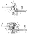
- the pinch feeding conveyor 44 has an upper conveyor 66 comprising a resilient dense foam conveyor belt riding on guide rollers 70.
- Pinch feeding conveyor 44 also has a lower conveyor 72 comprising a conveyor belt 74 riding atop a hard platform 76 which terminates at a guide wheel 78 for the lower conveyor belt 74.
- a first frame member 80 at the first side of the pinch feeding conveyor 44 supports guide wheel 78 and, therefore, lower conveyor 72.
- First frame number 80 also supports first plough 48 by way of adjustable plough support 84. It will be noted that the first frame member 80 extends downwardly from the lower conveyor 72.
- a second frame member 82 at the second side of the pinch feeding conveyor 44 supports the upper conveyor 66 by reason of supporting each of the guide rollers 70 of this conveyor.
- Frame member 82 also supports an adjustable plough support 86 for plough 50. It will be noted that the second frame member extends upwardly from the upper conveyor 66. (For clarity, the adjustable plough supports have been omitted from Figure 3).
- a first pair of pinch rollers 90 is supported by the first frame member 80 at the first side of the pinch feeding conveyor 44 proximate the downstream end 62 of the pinch feeding conveyor.
- a second pair of pinch rollers 92 is supported by the second frame member 82 at the second side of the pinch feeding conveyor 44 in line with the first pair of pinch rollers 90.
- the second frame member 82 has a lateral extension 94 on which is mounted a cowling 96 terminating in a flange 97.
- Frame 80 has a lateral extension 98 on which is mounted lower conveyor platform 76 and a cowling 100 terminating in flange 102.
- plough 48 changes from having a circular cross-section upstream of the pinch rollers 90 to having a half-circular cross-section downstream of these pinch rollers 90. This is to allow the pinch rollers to be closely positioned with respect to the plough.
- Plough 50 is similarly designed.
- a sheet of paper 24 fed to alignment table 12 is moved by the alignment table 12 into abutment with alignment edge 26 as it feeds downstream on the table.
- the sheet 24 enters scoring station 14 the sheet is scored at lines 32 and 34 thereby dividing the sheet into a medial panel 36 and first and second peripheral panels 38 and 40, respectively.
- the sheet exits the scoring station 14 it is taken up by pinch feeding conveyor 44. More particularly, the medial panel 36 of the sheet is pinched between the upper resilient conveyor belt 68 and the lower conveyor belt 74 of the pinch feeding conveyor 44 and fed downstream by these belts.
- cowling 96 prevents peripheral panel 38 from contacting the pinch feeding conveyor 44 and cowling 100 prevents peripheral panel 40 from contacting the pinch feeding conveyor 44.
- the sheet is sandwiched between flange 97 of cowling 96 and plough 48 at the first side of the pinch feeding conveyor 44 and between flange 102 of cowling 100 and plough 50 at the second side of the pinch feeding conveyor 44.
- the flange 97 acts as a backing plate for plough 48
- flange 102 acts as a backing plate for plough 50.
- the sheet is therefore quite constrained at this stage of its progression through the folder 42 so that the folded edges of the sheet are predictable placed. This placement is in line with pinch roller 90,92 so that these folded edges pass through the pinch rollers 90, 92 and are creased in order to iron the fold between the medial panel and each peripheral panel 38, 40 of the sheet 24.
- first frame member 80 at the first side of the pinch feeding conveyor and having the second frame member 82 extend upwardly from the pinch feeding conveyor 44, the second peripheral panel 40 is free to fold farther than it would have been allowed to do should the second frame member 82 have extended below the pinch feeding conveyor 44.
- frame member 82 extending along the second side of the pinch feeding conveyor 44 and the first frame member 80 extending downwardly from the pinch feeding conveyor, panel 38 is free to fold further than it would have been allowed to do should first frame member 80 have extended above the pinch feeding conveyor 44.
- this arrangement permits more complete folding of the sheet 24 in the folding station 16.
- Extension 48E of plough 48 extends beyond downstream end 62 and overlies panel 38.
- Extension 50E of plough 50 extends beyond downstream end 62 and underlies panel 40.
- Both plough extensions 48E, 50E extend toward folded sheet conveyor 18 so as to ensure the sheet 24F falls on top of this conveyor 18. More particularly, the downward dip of each extension assists in directing the sheets to the conveyor 18 and the inward incline of each extension results in each sheet being more fully supported than it would be if the extensions paralleled the downstream direction 22 of the folder 10.
- the letter sheet may land on downstream conveyor 18 somewhat skewed as illustrated in Figure 1. Nevertheless, these extensions ensure the letter sheet does land on folded sheet conveyor 18 in a reasonably controlled fashion such that the letter sheets will pass under the feed wheels 58 resting on conveyor 18 so that the sheets will be maintained in a folded condition as they move along this conveyor. Downstream of conveyor 18, a registration device may be provided to realign the folded letter sheets 24F.
- the folder 10 may be employed with sheets of a variety of thicknesses. Alternatively, sheets with credit cards or other inserts affixed to the medial panel may also be feed through the folder 10.
- the upper conveyor has been described as a resilient conveyor belt riding on wheels, this could be replaced with a plurality of resilient wheels.
- the upper conveyor could be a standard generally non-resilient belt riding on floating feed wheels with a spring pressure bar overlying the upper conveyor to provide a constant spring pressure urging this upper conveyor into pinching relationship with the lower conveyor.
- the upper conveyor could be non-resilient and the lower conveyor made resilient.
- ploughs 48 and 50 with their extensions 48E, 50E have been shown as integral bars, the ploughs could have other configurations and their extensions could be separate parts.
- folder 10 is arranged for Z-folding of letter sheets, it will be appreciated that it may easily be modified to form a traditional letter folds in a sheet (i.e., each peripheral panel is folded up and over the medial panel of the sheet). Other modifications will be apparent to those skilled in the art and, therefore, the invention is defined in the claims.
Landscapes
- Folding Of Thin Sheet-Like Materials, Special Discharging Devices, And Others (AREA)
Claims (13)
- Vorrichtung zum sofortigen Falzen von Bögen, umfassend:und dadurch gekennzeichnet, dassein Andrucktransportband (44) zum Andrucktransport eines Mittelteiles (36) eines geschnittenen Bogens (24), wobei der genannte Bogens (24) nach hinten transportiert wird;einen ersten Abstreicher (48), der parallel zu einer ersten Seite des genannten Andrucktransportbandes (44) verläuft und für das fortschreitende Falzen eines ersten Randfeldes (38) des genannten Bogens (24) während des Transportes des genannten Bogens durch das genannte Andrucktransportband (44) bestimmt ist;einen zweiten Abstreicher (50), der parallel zu einer zweiten gegenüberliegenden Seite des genannten Andrucktransportbandes (44) verläuft und für das fortschreitende Falzen eines zweiten Randfeldes (40) des genannten Bogens (24) während des Transportes des genannten Bogens durch das genannte Andrucktransportband (44) bestimmt ist;ein Falzbogenförderband (18), das unterhalb und hinter dem genannten Andrucktransportband (44) verläuft und für den Transport der das Andrucktransportband (44) verlassenden Bögen (24) bestimmt ist;der genannte erste Abstreicher (48) hinter einem hinteren Ende (62) des genannten Andrucktransportbandes (44) und in Richtung des genannten Falzbogenbandes (18) verläuft und dazu bestimmt ist, die Führung des genannten Bogens (24) zu dem genannten Falzbogenförderband (18) zu unterstützen;der genannte zweite Abstreicher (50) hinter einem hinteren Ende (62) des genannten Andrucktransportbandes (44) und in Richtung des genannten Falzbogenbandes (18) verläuft und dazu bestimmt ist, die Führung des genannten Bogens (24) zu dem genannten Falzbogenförderband (18) zu unterstützen.
- Vorrichtung zum sofortigen Falzen von Bögen nach Anspruch 1, in der das genannte Andrucktransportband ein oberes Förderband und ein unteres Förderband umfasst, und die mit einem ersten Rahmenelement an der genannten ersten Seite eines genannten Andrucktransportbandes zur Abstützung des genannten unteren Förderbandes und des genannten ersten Abstreichers sowie mit einem zweiten Rahmenelement an der genannten zweiten Seite des genannten Andrucktransportbandes zur Abstützung des genannten oberen Förderbandes und des genannten ersten Abstreichers ausgestattet ist.
- Vorrichtung zum sofortigen Falzen von Bögen nach Anspruch 2, in der das genannte erste Rahmenelement von dem genannten unteren Förderband ausgehend nach unten verläuft und das genannte zweite Rahmenelement von dem genannten oberen Förderband ausgehend nach oben verläuft.
- Vorrichtung zum sofortigen Falzen von Bögen nach Anspruch 1, umfassend ein erstes Paar von Andruckwalzen an der genannten ersten Seite des genannten Andrucktransportbandes in der Nähe des genannten hinteren Endes des genannten Andrucktransportbandes zum Andrücken des genannten Bogens an einem durch den genannten ersten Abstreicher zwischen dem genannten ersten Randfeld und einem Mittelfeld des genannten Bogens hergestellten Falz zum Zwecke der Faltung des genannten Falzes und umfassend ein zweites Paar von Andruckwalzen an der genannten zweiten Seite des genannten Andrucktransportbandes in der Nähe des genannten hinteren Endes des genannten Andrucktransportbandes zum Andrücken des genannten Bogens an einem durch den genannten zweiten Abstreicher zwischen dem genannten zweiten Randfeld des genannten Bogens und dem genannten Mittelfeld des genannten Bogens hergestellten Falz zum Zwecke der Faltung des genannten Falzes.
- Vorrichtung zum sofortigen Falzen von Bögen nach Anspruch 4, umfassend eine Ritzstation vor dem genannten ersten Abstreicher und genannten zweiten Abstreicher mit einem ersten Ritzwerkzeug zum Ritzen des genannten Bogens zwischen dem genannten Mittelfeld und dem genannten ersten Randfeld und einem zweiten Ritzwerkzeug zum Ritzen des genannten Bogens zwischen dem genannten Mittelfeld und dem genannten zweiten Randfeld.
- Vorrichtung zum sofortigen Falzen von Bögen nach Anspruch 1, in der das genannte obere Förderband oder das genannte untere Förderband federnd angeordnet ist, wodurch das genannte Andrucktransportband in der Lage ist, starke Bögen oder Bögen mit daran befestigten Einsätzen zu fördern.
- Vorrichtung zum sofortigen Falzen von Bögen nach Anspruch 5, in der das genannte Falzbogenförderband eine Breite hat, die größer als die Breite zwischen dem genannten ersten Ritzwerkzeug und dem genannten zweiten Ritzwerkzeug ist, wodurch das genannte Falzbogenförderband schräg auf dem Falzbogenförderband ankommende Falzbögen aufnehmen kann.
- Vorrichtung zum sofortigen Falzen von Bögen nach Anspruch 7, umfassend ein auf dem genannten Falzbogenförderband hinter einem vorderen Ende des genannten Falzbogenförderbandes montiertes Transportrad, um die Bögen auf dem Falzbogenförderband im gefalzten Zustand zu halten.
- Vorrichtung zum sofortigen Falzen von Bögen nach Anspruch 1, in der ein Teil des hinter einem hinteren Ende des genannten Andrucktransportbandes und in Richtung des genannten Falzbogenförderbandes verlaufenden genannten ersten Abstreichers zu einem Teil eines hinter dem genannten hinteren Ende des genannten Andrucktransportbandes und in Richtung des genannten Falzbogenförderbandes verlaufenden genannten zweiten Abstreichers hin geneigt ist.
- Vorrichtung zum sofortigen Falzen von Bögen nach Anspruch 9, in der das genannte Verlängerungsteil des zweiten Abstreichers zu dem genannten Verlängerungsteil des ersten Abstreichers hin geneigt ist.
- Vorrichtung zum sofortigen Falzen von Bögen nach Anspruch 1, in der der genannte erste Abstreicher so angeordnet ist, dass er das genannte erste Randfeld in einer ersten Richtung faltet und der genannte zweite Abstreicher so angeordnet ist, dass er das genannte zweite Randfeld in einer zweiten, der ersten Richtung entgegengesetzten Richtung faltet, wodurch ein z-förmiger Falz in dem genannten Bogen entsteht.
- Vorrichtung zum sofortigen Falzen von Bögen nach Anspruch 1, in der der genannte erste Abstreicher weiter als der genannte zweite Abstreicher hinter das genannte hintere Ende des genannten Andrucktransportbandes verläuft.
- Vorrichtung zum sofortigen Falzen von Bögen nach Anspruch 1, in derder genannte erste Abstreicher bis hinter ein hinteres Ende des genannten Andrucktransportbandes verläuft und nach unten in Richtung des genannten Falzbogenförderbandes geneigt ist, um die Führung des genannten Bogens auf das genannte Falzbogenförderband zu unterstützen;der genannte zweite Abstreicher bis hinter das genannte hintere Ende des genannten Andrucktransportbandes verläuft und nach unten in Richtung des genannten Falzbogenförderbandes geneigt ist, um die Führung des genannten Bogens auf das genannte Falzbogenförderband zu unterstützen.
Applications Claiming Priority (3)
| Application Number | Priority Date | Filing Date | Title |
|---|---|---|---|
| US08/663,395 US6312371B1 (en) | 1996-06-13 | 1996-06-13 | On-the-fly cut sheet folder |
| US663395 | 1996-06-13 | ||
| PCT/CA1997/000401 WO1997047550A1 (en) | 1996-06-13 | 1997-06-11 | On-the-fly cut sheet folder |
Publications (2)
| Publication Number | Publication Date |
|---|---|
| EP0912439A1 EP0912439A1 (de) | 1999-05-06 |
| EP0912439B1 true EP0912439B1 (de) | 2001-11-07 |
Family
ID=24661620
Family Applications (1)
| Application Number | Title | Priority Date | Filing Date |
|---|---|---|---|
| EP97924825A Expired - Lifetime EP0912439B1 (de) | 1996-06-13 | 1997-06-11 | Vorrichtung zum sofortigen falzen von bögen |
Country Status (6)
| Country | Link |
|---|---|
| US (1) | US6312371B1 (de) |
| EP (1) | EP0912439B1 (de) |
| JP (1) | JP2000511857A (de) |
| AU (1) | AU3020597A (de) |
| DE (1) | DE69708099T2 (de) |
| WO (1) | WO1997047550A1 (de) |
Families Citing this family (2)
| Publication number | Priority date | Publication date | Assignee | Title |
|---|---|---|---|---|
| CA2351264C (en) * | 2000-06-28 | 2009-11-03 | Grant Muir | Machine for repeatedly folding a sheet of foil to create a layered edge |
| IT1396784B1 (it) * | 2009-11-25 | 2012-12-14 | Gingardi | Apparecchiatura per la finitura dei prodotti uscenti da una macchina per la piegatura ed incollatura di prodotti in cartone o cartoncino con dorso. |
Family Cites Families (10)
| Publication number | Priority date | Publication date | Assignee | Title |
|---|---|---|---|---|
| US2088805A (en) | 1935-01-02 | 1937-08-03 | Olm | Machine for making file folders |
| US3642270A (en) * | 1969-09-26 | 1972-02-15 | Super Laundry Machinery Co | Small piece laundry folding machine |
| GB1460487A (en) | 1974-03-22 | 1977-01-06 | Spicers Ltd | Folding device for envelopes |
| US4022457A (en) | 1975-06-09 | 1977-05-10 | Pitney-Bowes, Inc. | Sheet folding device |
| DE3216505A1 (de) * | 1982-05-03 | 1983-11-03 | Windmöller & Hölscher, 4540 Lengerich | Vorrichtung zum z-foermigen falten von papiersaecken |
| US4588393A (en) * | 1983-05-24 | 1986-05-13 | Sun Chemical Corporation | Apparatus and method for folding cut sheet paper |
| CH668412A5 (en) | 1984-04-02 | 1988-12-30 | Juan Antonio Soriano | Paper adhesive coating and folding machine - has liquid adhesive dispensed via spring loaded ball end dispensers |
| US5037365A (en) * | 1989-12-20 | 1991-08-06 | Harris Graphics Corporation | Folder with belt speed control |
| DE4035106A1 (de) | 1990-11-05 | 1992-05-07 | Hunkeler Deutschland Gmbh | Falzmaschine |
| WO1993010980A1 (en) | 1991-11-29 | 1993-06-10 | Long, John, Albert | Continuous form and apparatus for forming letter sheets therefrom |
-
1996
- 1996-06-13 US US08/663,395 patent/US6312371B1/en not_active Expired - Fee Related
-
1997
- 1997-06-11 EP EP97924825A patent/EP0912439B1/de not_active Expired - Lifetime
- 1997-06-11 WO PCT/CA1997/000401 patent/WO1997047550A1/en not_active Ceased
- 1997-06-11 JP JP10501011A patent/JP2000511857A/ja active Pending
- 1997-06-11 DE DE69708099T patent/DE69708099T2/de not_active Expired - Fee Related
- 1997-06-11 AU AU30205/97A patent/AU3020597A/en not_active Abandoned
Also Published As
| Publication number | Publication date |
|---|---|
| WO1997047550A1 (en) | 1997-12-18 |
| JP2000511857A (ja) | 2000-09-12 |
| US6312371B1 (en) | 2001-11-06 |
| DE69708099D1 (de) | 2001-12-13 |
| DE69708099T2 (de) | 2002-06-06 |
| EP0912439A1 (de) | 1999-05-06 |
| AU3020597A (en) | 1998-01-07 |
Similar Documents
| Publication | Publication Date | Title |
|---|---|---|
| US4395255A (en) | Web folding apparatus | |
| US8628457B2 (en) | Method for folding sheets | |
| EP0836938B1 (de) | Falzapparat ohne Punkturnadeln | |
| JP3176836U (ja) | 搬送装置を備える折り機 | |
| EP0912439B1 (de) | Vorrichtung zum sofortigen falzen von bögen | |
| JP3968368B2 (ja) | シートの折り畳み設備 | |
| US4493482A (en) | Motion stabilizing and aligning apparatus for moving folded signatures through an ink jet printer | |
| EP0779862B1 (de) | Verfahren zum Herstellen eines Briefumschlags mit gefalteter Einlage | |
| US3972520A (en) | Apparatus for handling business forms | |
| JP2000510430A (ja) | 折り装置 | |
| US20180002049A1 (en) | Wrapping group and wrapping method for wrapping products, in particular editorial products, in containment bands | |
| DK200601682A (en) | Method and apparatus for wrapping a stack with a wrapping sheet | |
| US5106069A (en) | Apparatus for positioning covers on stacks of superimposed sheets | |
| KR102229052B1 (ko) | 자동 급지장치 | |
| US7513859B2 (en) | Folding device for printing presses or folders | |
| JPS61217476A (ja) | シ−ト折り装置 | |
| JPH0774059B2 (ja) | 枚葉紙支持装置 | |
| US4530687A (en) | Dual cutoff system having diverging web paths | |
| US1725309A (en) | Folding device | |
| US8752815B2 (en) | System and method for processing multi-page mail pieces | |
| KR20250055589A (ko) | 불규칙한 에지를 위한 정렬 모듈 | |
| JPH05338910A (ja) | 紙折機 | |
| JPH11139684A (ja) | チョッパ装置の折丁ガイド付き折丁停止装置 | |
| JP4939904B2 (ja) | 折り機 | |
| US1725837A (en) | Cross-folding machine |
Legal Events
| Date | Code | Title | Description |
|---|---|---|---|
| PUAI | Public reference made under article 153(3) epc to a published international application that has entered the european phase |
Free format text: ORIGINAL CODE: 0009012 |
|
| 17P | Request for examination filed |
Effective date: 19990111 |
|
| AK | Designated contracting states |
Kind code of ref document: A1 Designated state(s): DE ES FR GB NL |
|
| GRAG | Despatch of communication of intention to grant |
Free format text: ORIGINAL CODE: EPIDOS AGRA |
|
| 17Q | First examination report despatched |
Effective date: 20001214 |
|
| GRAG | Despatch of communication of intention to grant |
Free format text: ORIGINAL CODE: EPIDOS AGRA |
|
| GRAH | Despatch of communication of intention to grant a patent |
Free format text: ORIGINAL CODE: EPIDOS IGRA |
|
| GRAH | Despatch of communication of intention to grant a patent |
Free format text: ORIGINAL CODE: EPIDOS IGRA |
|
| RAP1 | Party data changed (applicant data changed or rights of an application transferred) |
Owner name: LONGFORD EQUIPMENT INTERNATIONAL LIMITED |
|
| RIN1 | Information on inventor provided before grant (corrected) |
Inventor name: LONGFORD EQUIPMENT INTERNATIONAL LIMITED |
|
| GRAA | (expected) grant |
Free format text: ORIGINAL CODE: 0009210 |
|
| AK | Designated contracting states |
Kind code of ref document: B1 Designated state(s): DE ES FR GB NL |
|
| REF | Corresponds to: |
Ref document number: 69708099 Country of ref document: DE Date of ref document: 20011213 |
|
| REG | Reference to a national code |
Ref country code: GB Ref legal event code: IF02 |
|
| RIN2 | Information on inventor provided after grant (corrected) |
Free format text: LONG, JOHN A. |
|
| ET | Fr: translation filed | ||
| PG25 | Lapsed in a contracting state [announced via postgrant information from national office to epo] |
Ref country code: ES Free format text: LAPSE BECAUSE OF FAILURE TO SUBMIT A TRANSLATION OF THE DESCRIPTION OR TO PAY THE FEE WITHIN THE PRESCRIBED TIME-LIMIT Effective date: 20020530 |
|
| PLBE | No opposition filed within time limit |
Free format text: ORIGINAL CODE: 0009261 |
|
| STAA | Information on the status of an ep patent application or granted ep patent |
Free format text: STATUS: NO OPPOSITION FILED WITHIN TIME LIMIT |
|
| 26N | No opposition filed | ||
| PGFP | Annual fee paid to national office [announced via postgrant information from national office to epo] |
Ref country code: FR Payment date: 20060529 Year of fee payment: 10 |
|
| PGFP | Annual fee paid to national office [announced via postgrant information from national office to epo] |
Ref country code: GB Payment date: 20060530 Year of fee payment: 10 |
|
| PGFP | Annual fee paid to national office [announced via postgrant information from national office to epo] |
Ref country code: DE Payment date: 20060531 Year of fee payment: 10 |
|
| PGFP | Annual fee paid to national office [announced via postgrant information from national office to epo] |
Ref country code: NL Payment date: 20060630 Year of fee payment: 10 |
|
| GBPC | Gb: european patent ceased through non-payment of renewal fee |
Effective date: 20070611 |
|
| NLV4 | Nl: lapsed or anulled due to non-payment of the annual fee |
Effective date: 20080101 |
|
| REG | Reference to a national code |
Ref country code: FR Ref legal event code: ST Effective date: 20080229 |
|
| PG25 | Lapsed in a contracting state [announced via postgrant information from national office to epo] |
Ref country code: NL Free format text: LAPSE BECAUSE OF NON-PAYMENT OF DUE FEES Effective date: 20080101 Ref country code: DE Free format text: LAPSE BECAUSE OF NON-PAYMENT OF DUE FEES Effective date: 20080101 |
|
| PG25 | Lapsed in a contracting state [announced via postgrant information from national office to epo] |
Ref country code: GB Free format text: LAPSE BECAUSE OF NON-PAYMENT OF DUE FEES Effective date: 20070611 |
|
| PG25 | Lapsed in a contracting state [announced via postgrant information from national office to epo] |
Ref country code: FR Free format text: LAPSE BECAUSE OF NON-PAYMENT OF DUE FEES Effective date: 20070702 |