EP0912307B1 - Scie manuelle a moteur - Google Patents
Scie manuelle a moteur Download PDFInfo
- Publication number
- EP0912307B1 EP0912307B1 EP97928601A EP97928601A EP0912307B1 EP 0912307 B1 EP0912307 B1 EP 0912307B1 EP 97928601 A EP97928601 A EP 97928601A EP 97928601 A EP97928601 A EP 97928601A EP 0912307 B1 EP0912307 B1 EP 0912307B1
- Authority
- EP
- European Patent Office
- Prior art keywords
- sprocket wheel
- wire loop
- cutting elements
- loop
- wire
- Prior art date
- Legal status (The legal status is an assumption and is not a legal conclusion. Google has not performed a legal analysis and makes no representation as to the accuracy of the status listed.)
- Expired - Lifetime
Links
Images


Classifications
-
- B—PERFORMING OPERATIONS; TRANSPORTING
- B23—MACHINE TOOLS; METAL-WORKING NOT OTHERWISE PROVIDED FOR
- B23D—PLANING; SLOTTING; SHEARING; BROACHING; SAWING; FILING; SCRAPING; LIKE OPERATIONS FOR WORKING METAL BY REMOVING MATERIAL, NOT OTHERWISE PROVIDED FOR
- B23D61/00—Tools for sawing machines or sawing devices; Clamping devices for these tools
- B23D61/18—Sawing tools of special type, e.g. wire saw strands, saw blades or saw wire equipped with diamonds or other abrasive particles in selected individual positions
- B23D61/185—Saw wires; Saw cables; Twisted saw strips
-
- B—PERFORMING OPERATIONS; TRANSPORTING
- B23—MACHINE TOOLS; METAL-WORKING NOT OTHERWISE PROVIDED FOR
- B23D—PLANING; SLOTTING; SHEARING; BROACHING; SAWING; FILING; SCRAPING; LIKE OPERATIONS FOR WORKING METAL BY REMOVING MATERIAL, NOT OTHERWISE PROVIDED FOR
- B23D57/00—Sawing machines or sawing devices not covered by one of the preceding groups B23D45/00 - B23D55/00
- B23D57/0007—Sawing machines or sawing devices not covered by one of the preceding groups B23D45/00 - B23D55/00 using saw wires
- B23D57/0015—Sawing machines or sawing devices not covered by one of the preceding groups B23D45/00 - B23D55/00 using saw wires hand-held or hand-operated
-
- B—PERFORMING OPERATIONS; TRANSPORTING
- B23—MACHINE TOOLS; METAL-WORKING NOT OTHERWISE PROVIDED FOR
- B23D—PLANING; SLOTTING; SHEARING; BROACHING; SAWING; FILING; SCRAPING; LIKE OPERATIONS FOR WORKING METAL BY REMOVING MATERIAL, NOT OTHERWISE PROVIDED FOR
- B23D57/00—Sawing machines or sawing devices not covered by one of the preceding groups B23D45/00 - B23D55/00
- B23D57/02—Sawing machines or sawing devices not covered by one of the preceding groups B23D45/00 - B23D55/00 with chain saws
-
- B—PERFORMING OPERATIONS; TRANSPORTING
- B28—WORKING CEMENT, CLAY, OR STONE
- B28D—WORKING STONE OR STONE-LIKE MATERIALS
- B28D1/00—Working stone or stone-like materials, e.g. brick, concrete or glass, not provided for elsewhere; Machines, devices, tools therefor
- B28D1/02—Working stone or stone-like materials, e.g. brick, concrete or glass, not provided for elsewhere; Machines, devices, tools therefor by sawing
- B28D1/08—Working stone or stone-like materials, e.g. brick, concrete or glass, not provided for elsewhere; Machines, devices, tools therefor by sawing with saw-blades of endless cutter-type, e.g. chain saws, i.e. saw chains, strap saws
Definitions
- the present invention relates to hand-held motor-driven saws of the kind comprising a machine housing with a handle, a drive motor, and a saw blade, in which the saw blade projects out from the machine housing and a continuous wire loop, which carries axially spaced cutting elements thereon, is arranged to run around the saw blade between a drive wheel in the drive motor and a loop-guiding sprocket wheel at the free end of the saw blade, the cutting width of the cutting elements being greater than the width of the saw blade and of the guide sprocket wheel.
- Portable power saws of this kind normally include belt-like elements in the form of chains comprised of mutually pivotal links that are guided in the longitudinal direction of guides on the saw blade. Examples of such saws are found in patent publications WO 88/04602 (EP A 293.399) and U.S. 4,654,972.
- the problem of wear is still critical at least in that part of the saw blade most subjected to strain, namely in the guide sprocket wheels at the outer ends of the bars.
- the stone debris that is generated becomes mixed with water and forms a sticky abrasive mass that quickly wears down joints and the surfaces of metal guides.
- sawing wood the wood cut repeatedly becomes clogged with sawdust, causing disturbances in the work on hand. This latter problem can be counteracted with the use of oil, although such use creates an environmental problem instead.
- Patent Publications U.S. 4,907,564 and U.S. 3,958,332 disclose examples of sawing stone and wood with the use of band-type elements other than linked saw chains, namely continuous wire loops on which cutting elements are mounted.
- a further example of this type of device is also known from DE-A-3,411,283.
- Available wire or cable constructions require the use of mechanical equipment when cutiing stone, often heavy equipment, which does not allow the portable power saw to be used in a typical comfortable manner, with plunging penetration of the guide sprocket wheel directly into stone or wood in the manner of a circular saw.
- the object of the present invention is to provide a portable power saw that includes a wire loop which carries cutting elements and which coacts with a guide sprocket wheel on the saw blade in a manner such as to enhance the wear strength and increase the useful life of the saw by virtue of improving the exclusion of debris cuttings and wood dust and chips, so that straight-in plunge cuts can be made effectively in the material being cut with the aid of the guide sprocket wheel, in the manner of a circular saw.
- a further object is to enable such a straight-in cut to be made to a depth that extends beyond the centre of the guide sprocket wheel with the aid of an enlarged guide sprocket wheel, therewith achieving with simple saw blade equipment a working method that has hitherto been reserved for ring saws with high tool costs.
- Another object is to provide a wire saw that can be provided with cutting elements having a directed abrasive or cutting effect without the cutting elements twisting as the wire loop runs around the saw blade.
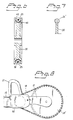
- the machine housing 15 of the power saw shown in Fig. 1 includes a conventional drive motor 16 of an appropriate kind (not described in detail), such as an hydraulic motor, an electric motor or an internal combustion motor, said motor including an output shaft 19 which carries a drive wheel 30.
- a conventional drive motor 16 of an appropriate kind such as an hydraulic motor, an electric motor or an internal combustion motor, said motor including an output shaft 19 which carries a drive wheel 30.
- the machine housing 15 includes a handle 21, 22 for handling the saw manually.
- a saw blade 17 extends out from the machine housing 15 and is secured thereto by means of suitable bolts 29.
- the outer end of the saw blade 17 carries a guide sprocket wheel 20 which is rotatable about a shaft 34 mounted in a bearing 36 (Fig. 5).
- sealing rings 37 the guide sprocket wheel 20 is sealed radially against respective sides of the saw blade 17 which grip around the guide sprocket wheel 20 and the bearing 36 in a fork-like manner.
- An endless band-element carrying cutting elements 25 and having the form of a closed wire loop 18 is tensioned to orbit around the drive wheel 30 and the guide sprocket wheel 20.
- the machine housing 15, in the region of the bolts 29, is in conventional manner associated with means, not shown, which keep the wire loop 18 taut against the drive wheel 30 and against the guide sprocket wheel 20 during revolving motion.
- a preferred embodiment of the wire loop 18 for use when sawing stone, concrete and brick is shown in Figs. 2, 3.
- circular-cylindrical, steel carrier cores 38 are fixed in uniform spaced relationship along the length of the wire loop 18 on a wire 40 comprised of twisted steel or plastic strands (e.g. KevlarTM).
- Each of the cores 38 carries a stone-cutting abrasive layer 39, e.g. a layer that includes diamond powder or boron nitride in a suitably applied matrix material; in respect of examples of material compare publication U.S. 4,907,564 mentioned hereinbefore by way of introduction.
- the wire 40 is covered with a suitable chip-repelling elastomeric casing 41 between the cores 38 of the cutting elements 25, said elastomeric casing having mutually opposing end-flanges 42 which abut against the ends of the cutting elements 25, i.e. the cores 38.
- the drive wheel 30 has a circumferential groove 45 which receives the wire loop 18 and the bottom of which has an elastomeric lining 46 which protects the bottom of the groove against wear in its driving cooperation with the cutting elements 25.
- the drive wheel 30 can be protected against wear by constructing the drive wheel in a manner analogous with the guide sprocket wheel 20 as described hereinafter with reference to Figs. 4, 5.
- the guide means are comprised of a peripheral groove 26 that is formed in the apices of respective teeth or sprockets 27 and extending circumferentially around the sprocket wheel 20, said groove functioning to guide and support the wire loop 18 tensioned against the sprocket wheel 20 in the groove 26 between the walls of said groove, such that the central plane of the wire loop 18 will coincide with the central plane of the sprocket wheel 20 and the cutting elements 25,suspended by those parts of the wire loop 18 that bridge or span the recesses 28, will hang freely in said recesses.
- the sprocket wheel 20 thus makes no wearing contact with the cutting elements 25.
- the sprockets 27 drop in between the elastomeric material of the end-flanges 42 and thus make no wearing contact with the metal. Neither shall the saw blade 17 as such be in wearing metallic contact with the cutting elements 25.
- the wire loop 18 is tensioned so that the loop will hang freely at a safe distance from the saw blade 17 at those parts where sawing work can occur with a manually applied feeding force. As shown in Fig. 1, this applies suitably to the entire bottom run of the wire loop and a major part of the upper run of said loop outside the machine housing 15.
- the wire loop 18 Since the wire or cable 40 of the wire loop 18 is twisted and joined to form a loop, preferably by splicing the mutually joined ends of the wire, the wire loop 18 will tend to twist about its longitudinal axis as it moves between the drive wheel and sprocket wheel. In the case of the circular cutting elements shown in Figs. 5, 6, this tendency is an advantage that can be further amplified by angularly offsetting the mutually joined ends of the wire when splicing or otherwise joining said ends, e.g. with the aid of a screw connector, in relation to the longitudinal axis of the wire loop 18 so as to obtain a loop that has a figure-of-eight configuration prior to fitting the loop.
- the thus amplified twisting tendency alternates in relation to the saw blade 17, the outwardly facing, active cutting cylindrical parts of the cutting elements 25, so as to utilise the whole of the cylindrical surface, which as such must be wider than the saw blade 17, for sawing.
- the free-hanging wire loop 18 and its similarly freely-hanging rotary cutting elements 25 make it much easier for water flushed through passageways 47 (Fig. 1) to prevent the ingress of debris cuttings when cutting stone and to prevent clogging, wear and operational disturbances, e.g. disturbances caused by the wire loop skewing and leaving its guides.
- Fig. 1 When sawing wood with one-sided alternative cutting elements, shown schematically in Fig. 7 and referenced 25' (provided with teeth, e.g. hard-metal teeth when necessary), the improved prevention of the ingress of sawdust and chips enables that the use of environmentally harmful oil, customarily supplied to the cutting elements in order to control blocking or clogging of the wood cut, can be omitted or at least greatly reduced.
- branches can be cut from a lying tree with a simple sideways movement of the free-hanging wire loop without needing to tilt the saw, since the cutting elements cut in all directions.
- the wire loop 18 forms a geared transmission from the drive wheel 30 to a guide sprocket wheel 20' which is enlarged with respect to diameter.
- the saw therewith obtains the effect of a circular saw, e.g. for sawing angular cuts to a depth that can be extended beyond the centre of the sprocket wheel 20'.
- Figs. 9-12 illustrate alternative guiding of the wire loop 18 around the periphery of the guide sprocket wheel 20, in the form of a duplicated construction of the wire loop divided into two separate, mutually adjacent thin wire parts 18', 18", i.e. wires coated with elastomeric material, which commonly carry the cutting elements 25 therebetween.
- the guide devices on the periphery of the guide sprocket wheel 20 are formed by a central cog cam 51 on each sprocket 27 that projects in between the wire-parts 18', 18" and guides said line-parts into coplanar abutment with abutment surfaces 52 on respective sides of the cog cams 51. This replaces the groove 26 of the Fig. 5 embodiment.
- the wire loop 18', 18" is unable to twist in the case of this embodiment and the cutting elements can therewith freely be given an irregular shape, e.g. a pointed saw-tooth shape, with solely a one-sided outwardly cutting form.
- Duplication of the wire loop in the wire-parts 18', 18" also enables the guide sprocket wheel to be made extremely thin and given the form of a flat and smoothly toothed disc 20, Fig.
- sprockets 27 with shoulders 53 and intermediate recesses 54 carry rungs 55 made of an elastomeric material or some other material and surrounding, joining and carrying the wire-parts 18', 18" hanging on respective sides of the tops 51 of the sprockets 27 during passage thereover with the common central plane of the wire-parts 18', 18" in plane with the guide sprocket wheel 27.
- the rungs 55 are indicated by broken reference lines in Fig. 11.
- the guide means of the guide sprocket wheel 20 has the form of a peripheral groove which receives the wire loop in shape-bound engagement.
- a wedge-shaped engagement between the groove 26''' and the wire loop 18''' is shown by way of example.
- This sort-of V-belt shaped engagement prevents the wire loop 18''' from twisting about its long axis, so as to make one-sided cutting possible, e.g. with the aid of a simple and irregularly shaped cutting element 25.
Landscapes
- Engineering & Computer Science (AREA)
- Mechanical Engineering (AREA)
- Mining & Mineral Resources (AREA)
- Processing Of Stones Or Stones Resemblance Materials (AREA)
- Sawing (AREA)
- Manufacturing And Processing Devices For Dough (AREA)
- Finish Polishing, Edge Sharpening, And Grinding By Specific Grinding Devices (AREA)
Claims (10)
- Scie manuelle à moteur comprenant un logement de machine (15) avec une poignée, un moteur (16) et une lame de scie (17), dans laquelle la lame de scie (17) se projette à l'extérieur du logement de machine (15) et une boucle de câble continue (18), qui porte des éléments de découpe (25) espacés axialement sur celle-ci, est agencée pour tourner autour de la lame de scie (17) entre une roue d'entraínement (30) dans le moteur (16) et une roue dentée de guidage de boucle (20) au niveau de l'extrémité libre de la lame de scie (17), la largeur de découpe des éléments de découpe (25) étant plus importante que la largeur de la lame de scie (17) et de la roue dentée de guidage (20), caractérisée par des moyens de guidage (26) sur la périphérie de la roue dentée (20) conçus pour maintenir la boucle de câble (18) à plat sur la roue dentée (20) lorsque la boucle de câble (18) tourne autour de ladite roue dentée (20) et en ce que les éléments de découpe (25) sont conçus pour tomber dans des crans coactifs (28) situés sur la périphérie de la roue dentée (20) entre lesdits moyens de guidage (26) afin de permettre aux éléments de découpe (25) d'être librement suspendus dans ces éléments de la boucle de câble (18) qui enjambent les crans (28).
- Scie selon la revendication 1, caractérisée en ce que les éléments périphériques de la roue dentée (20) s'étendant entre les creux (28) forment des dents (27) qui servent à diriger les éléments de découpe (25) suspendus librement dans lesdits creux (28) sur la roue dentée (20) lorsque la boucle de câble (18) tourne autour de ladite roue dentée.
- Scie selon la revendication 2, caractérisée en ce que la boucle de câble (18) comprend au moins un câble (40) constitué de fils d'acier et de plastique torsadés ensemble.
- Scie selon la revendication 3, caractérisée en ce que les éléments de découpe (25) sont montés sur une âme support en acier portée par la boucle (38) et en ce que lesdits éléments de découpe présentent une couche abrasive de découpe de pierres dures (39) pour le travail de la pierre, ou bien possèdent des dents de découpe (25') pour le travail du bois ; et en ce que la section de câble (40) entre lesdits éléments de découpe (25, 25') est recouverte (41) d'un matériau élastomère, les brides d'extrémité (42) dudit matériau reposant contre les âmes support (38) et formant des butées latérales lors d'un contact avec les dents (27) sur la roue dentée (20).
- Scie selon la revendication 2, caractérisée en ce que les moyens de guidage sont formés par une gorge périphérique (26) autour de la roue dentée (20) formée dans les parties supérieures des dents (27).
- Scie selon la revendication 2, caractérisée en ce que la boucle de câble (18''') agit conjointement en fonction de la forme avec les dents ou tenons (27''') de manière à empêcher une torsion de la boucle de câble (18''') sur son axe longitudinal, moyennant quoi les éléments de découpe (25) vont découper activement avec constamment les mêmes surfaces qui sont distales de la lame de scie (17).
- Scie selon la revendication 2, caractérisée en ce que la boucle de câble (18) est doublée et divisée en deux parties de câble adjacentes séparées l'une de l'autre (18', 18'') qui portent les éléments de découpe (25) conjointement entre elles, et en ce que les moyens de guidage sont formés par lesdites dents (27) se trouvant dans le plan central de la roue dentée (20) et lesdites sections de câble (18', 18'') de telle sorte à empêcher une torsion de la boucle de câble (18) par pénétration entre lesdites sections de câble (18', 18") moyennant quoi les éléments de découpe (25) vont découper activement avec constamment les mêmes surfaces qui sont distales de la lame de scie (17).
- Scie selon la revendication 1 ou 2, caractérisée en ce que la boucle de câble (18) entre la roue d'entraínement (30) et la roue dentée (20) est tendu pour être suspendue librement par rapport à la lame de scie (17) avec un jeu total pendant l'opération de sciage, au moins dans le parcours inférieur de la boucle de câble (18).
- Scie selon l'une quelconque des revendications 1 à 5, caractérisée en ce que la boucle de câble (18) forme une transmission par engrenage depuis la roue d'entraínement (30) vers une roue dentée (20') de sciage, dont le diamètre est agrandi par rapport au diamètre de la roue d'entraínement (30) et avec un effet de scie circulaire à une profondeur de découpe au-delà du centre de rotation de la roue dentée de guidage (20).
- Scie selon la revendication 1, caractérisée en ce que les éléments de découpe (25) sur la boucle de câble (18) sont cylindriques ; en ce que les extrémités de la boucle de câble (18) sont raccordées ensemble de telle manière à être décalées angulairement par rapport à l'axe longitudinal de la boucle de câble (18), de telle sorte que la boucle de câble (18) se tordra autour de son axe longitudinal pendant son mouvement orbital et placera les parties cylindriques de découpe actives orientées vers l'extérieur des éléments de découpe (25) au niveau de la périphérie ; et en ce que la boucle de câble (18) comprend un câble (40) constitué de fils de plastique et d'acier torsadés ensemble qui ont été raccordés pour former une boucle, de préférence en épissant ensemble les extrémités de ladite boucle.
Applications Claiming Priority (3)
| Application Number | Priority Date | Filing Date | Title |
|---|---|---|---|
| SE9602371 | 1996-06-17 | ||
| SE9602371A SE509831C2 (sv) | 1996-06-17 | 1996-06-17 | Handhållen motordriven såg |
| PCT/SE1997/001074 WO1997048532A1 (fr) | 1996-06-17 | 1997-06-17 | Scie manuelle a moteur |
Publications (2)
| Publication Number | Publication Date |
|---|---|
| EP0912307A1 EP0912307A1 (fr) | 1999-05-06 |
| EP0912307B1 true EP0912307B1 (fr) | 2002-08-28 |
Family
ID=20403022
Family Applications (1)
| Application Number | Title | Priority Date | Filing Date |
|---|---|---|---|
| EP97928601A Expired - Lifetime EP0912307B1 (fr) | 1996-06-17 | 1997-06-17 | Scie manuelle a moteur |
Country Status (8)
| Country | Link |
|---|---|
| US (1) | US6178960B1 (fr) |
| EP (1) | EP0912307B1 (fr) |
| AT (1) | ATE222844T1 (fr) |
| CA (1) | CA2258522C (fr) |
| DE (1) | DE69715004T2 (fr) |
| ES (1) | ES2183188T3 (fr) |
| SE (1) | SE509831C2 (fr) |
| WO (1) | WO1997048532A1 (fr) |
Families Citing this family (22)
| Publication number | Priority date | Publication date | Assignee | Title |
|---|---|---|---|---|
| SE513484C2 (sv) * | 1998-01-21 | 2000-09-18 | Hagby Asahi Ab | Sågrem och betongsåg |
| DE19960460B4 (de) * | 1999-12-15 | 2008-11-27 | Andreas Stihl Ag & Co. | Führungschiene mit drehenden Leitscheiben |
| ES2505250T3 (es) * | 2002-02-04 | 2014-10-09 | P & M Services, Inc. | Convertidor de rollo de papel cortado por penetración |
| US20060260458A1 (en) * | 2005-05-23 | 2006-11-23 | Gary Friend | Powered and ergonomically configured portable coping saw for one-handed use |
| US10259135B2 (en) * | 2007-02-26 | 2019-04-16 | Pellenc (Societe Anonyme) | Chainsaw apparatus having lubricating system |
| FR2912948B1 (fr) * | 2007-02-26 | 2010-02-12 | Pellenc Sa | Scie a chaine pourvue d'un dispositif de lubrification et procede mis en oeuvre pour realiser cette lubrification |
| US8225515B2 (en) * | 2007-04-06 | 2012-07-24 | Ruth Brian J | Chainsaw carving guide bar |
| DE102008021142A1 (de) | 2007-12-03 | 2009-06-04 | Bernhard Brehm | Handseilsäge |
| ATE497854T1 (de) | 2008-04-28 | 2011-02-15 | Bernhard Brehm | Handseilsäge |
| US9314253B2 (en) | 2008-07-01 | 2016-04-19 | Amendia, Inc. | Tissue modification devices and methods |
| MX348805B (es) * | 2008-07-14 | 2017-06-28 | Baxano Inc | Dispositivo de modificación de tejidos. |
| US20110072944A1 (en) * | 2009-09-29 | 2011-03-31 | Jeffrey Eggers | Flexible linked cutting system |
| CN102179878B (zh) * | 2011-03-25 | 2014-12-10 | 厦门致力金刚石科技股份有限公司 | 一种新型金刚石绳锯机 |
| AT513117B1 (de) * | 2012-06-28 | 2016-04-15 | Markus Hatzer | Fräse |
| WO2014184753A1 (fr) * | 2013-05-17 | 2014-11-20 | Meyer Burger Ag | Machine à scier à fil ayant des poulies à évidements |
| EP2826607A1 (fr) * | 2013-07-15 | 2015-01-21 | Pavatex SA | Dispositif de coupe pour plaques en fibres de bois |
| US9616512B1 (en) * | 2014-04-25 | 2017-04-11 | Paul Viola | Inherently thin single width chain |
| WO2016046740A1 (fr) * | 2014-09-24 | 2016-03-31 | Dario Toncelli | Outil et machine pour travailler de la pierre naturelle, un agglomérat ou un matériau céramique |
| US10138685B1 (en) | 2015-12-18 | 2018-11-27 | Jeffrey Eggers | Drilling system with teeth driven in opposite directions |
| US10900354B2 (en) * | 2016-08-29 | 2021-01-26 | Huthaifa Eilouti | Drilling and cutting device |
| SE543428C2 (en) * | 2019-06-24 | 2021-02-16 | Husqvarna Ab | A rotatable cutting chain work tool, a wall saw arrangement comprising such a work tool, an annular member and a method for producing an annular member |
| CN112248249B (zh) * | 2020-10-23 | 2022-04-01 | 泉州市利器金刚石工具有限公司 | 一种金刚石绳锯 |
Family Cites Families (12)
| Publication number | Priority date | Publication date | Assignee | Title |
|---|---|---|---|---|
| US3958332A (en) | 1975-04-14 | 1976-05-25 | Gates Elmer L | Cable saw |
| US4271738A (en) | 1979-04-23 | 1981-06-09 | Deangelis Eugene R | Sawing machine |
| FR2555093B1 (fr) | 1983-11-23 | 1986-12-26 | Horst Sellmaier | Guide de tronconneuse |
| US4580545A (en) * | 1984-02-29 | 1986-04-08 | Florida Wire And Cable Company | Stone sawing strand |
| DE3411283A1 (de) * | 1984-03-27 | 1984-08-30 | Herbert Bauch | Saegeseil fuer motorsaegen |
| FR2581916B1 (fr) * | 1985-05-20 | 1987-07-24 | Arrive Sa | Dispositif de decoupe, notamment entre deux zones de durete differente |
| US4856490A (en) * | 1987-09-09 | 1989-08-15 | Osaka Diamond Industrial Co., Ltd. | Wire saw |
| US4907564A (en) | 1987-11-24 | 1990-03-13 | Sumitomo Rubber Industries, Ltd. | Wire saw |
| DE3811265A1 (de) * | 1988-04-02 | 1989-10-12 | Falkenstein J Masch Verzahnung | Saegewerkzeug mit angepasster saegemaschine |
| US5218949A (en) * | 1990-03-19 | 1993-06-15 | Tomlinson Peter N | Saws |
| AT393988B (de) * | 1990-04-03 | 1992-01-10 | Swarovski Tyrolit Schleif | Saegeseil |
| US5216999A (en) * | 1991-01-25 | 1993-06-08 | Ehwa Diamond Ind. Co., Ltd. | Wire saw |
-
1996
- 1996-06-17 SE SE9602371A patent/SE509831C2/sv not_active IP Right Cessation
-
1997
- 1997-06-17 ES ES97928601T patent/ES2183188T3/es not_active Expired - Lifetime
- 1997-06-17 AT AT97928601T patent/ATE222844T1/de not_active IP Right Cessation
- 1997-06-17 CA CA002258522A patent/CA2258522C/fr not_active Expired - Fee Related
- 1997-06-17 EP EP97928601A patent/EP0912307B1/fr not_active Expired - Lifetime
- 1997-06-17 DE DE69715004T patent/DE69715004T2/de not_active Expired - Fee Related
- 1997-06-17 WO PCT/SE1997/001074 patent/WO1997048532A1/fr active IP Right Grant
-
1998
- 1998-12-14 US US09/210,660 patent/US6178960B1/en not_active Expired - Fee Related
Also Published As
| Publication number | Publication date |
|---|---|
| CA2258522C (fr) | 2005-03-29 |
| ATE222844T1 (de) | 2002-09-15 |
| EP0912307A1 (fr) | 1999-05-06 |
| CA2258522A1 (fr) | 1997-12-24 |
| DE69715004T2 (de) | 2003-05-08 |
| DE69715004D1 (de) | 2002-10-02 |
| SE9602371D0 (sv) | 1996-06-17 |
| WO1997048532A1 (fr) | 1997-12-24 |
| ES2183188T3 (es) | 2003-03-16 |
| SE9602371L (sv) | 1997-12-18 |
| US6178960B1 (en) | 2001-01-30 |
| SE509831C2 (sv) | 1999-03-15 |
Similar Documents
| Publication | Publication Date | Title |
|---|---|---|
| EP0912307B1 (fr) | Scie manuelle a moteur | |
| EP1049556B1 (fr) | Cable de scie | |
| JP4216081B2 (ja) | 工具ユニットと、切断すなわち鋸引き用の機械 | |
| US5603311A (en) | Belt based cutting system | |
| EP0320456B1 (fr) | Scie sous forme de bande pour couper des rainures dans pierres | |
| US5735259A (en) | High speed cutting belt | |
| US4679541A (en) | Belt-configured saw for cutting slots into stone | |
| EP0907448B1 (fr) | Scie a fil | |
| WO2004009278A1 (fr) | Dispositif d'entrainement de scie circulaire et dispositif de coupe a scie circulaire | |
| WO1997048514A9 (fr) | Scie a fil | |
| US4603678A (en) | Belt-configured saw for cutting slots into stone | |
| CN113021650A (zh) | 绳锯机构和石材切割用绳锯装置 | |
| US4461269A (en) | Stonecutter sprocket having replaceable carbide steel teeth | |
| US20190217497A1 (en) | Utility Chain For Cutting Ductile Materials | |
| US11911926B2 (en) | Link elements for improved flexible abrasive cutting tools | |
| WO2001023128A1 (fr) | Lame de scie a chaine non lubrifiee | |
| JP4418981B2 (ja) | リングソーの駆動装置及びリングソー付き切断装置 | |
| JPH0577227A (ja) | 石材切断用のフレキシブル工具 | |
| KR200386290Y1 (ko) | 와이어 쏘오 | |
| RU2134633C1 (ru) | Пильный орган ленточнопильного станка | |
| SU1209879A1 (ru) | Исполнительный орган баровой пилы | |
| GB190810946A (en) | Improvements in or relating to Machinery for Cutting Coal |
Legal Events
| Date | Code | Title | Description |
|---|---|---|---|
| PUAI | Public reference made under article 153(3) epc to a published international application that has entered the european phase |
Free format text: ORIGINAL CODE: 0009012 |
|
| 17P | Request for examination filed |
Effective date: 19981205 |
|
| AK | Designated contracting states |
Kind code of ref document: A1 Designated state(s): AT BE CH DE DK ES FI FR GB IE IT LI MC NL PT SE |
|
| GRAG | Despatch of communication of intention to grant |
Free format text: ORIGINAL CODE: EPIDOS AGRA |
|
| GRAG | Despatch of communication of intention to grant |
Free format text: ORIGINAL CODE: EPIDOS AGRA |
|
| GRAH | Despatch of communication of intention to grant a patent |
Free format text: ORIGINAL CODE: EPIDOS IGRA |
|
| 17Q | First examination report despatched |
Effective date: 20020219 |
|
| GRAH | Despatch of communication of intention to grant a patent |
Free format text: ORIGINAL CODE: EPIDOS IGRA |
|
| GRAA | (expected) grant |
Free format text: ORIGINAL CODE: 0009210 |
|
| AK | Designated contracting states |
Kind code of ref document: B1 Designated state(s): AT BE CH DE DK ES FI FR GB IE IT LI MC NL PT SE |
|
| PG25 | Lapsed in a contracting state [announced via postgrant information from national office to epo] |
Ref country code: NL Free format text: LAPSE BECAUSE OF FAILURE TO SUBMIT A TRANSLATION OF THE DESCRIPTION OR TO PAY THE FEE WITHIN THE PRESCRIBED TIME-LIMIT Effective date: 20020828 Ref country code: LI Free format text: LAPSE BECAUSE OF FAILURE TO SUBMIT A TRANSLATION OF THE DESCRIPTION OR TO PAY THE FEE WITHIN THE PRESCRIBED TIME-LIMIT Effective date: 20020828 Ref country code: FI Free format text: LAPSE BECAUSE OF FAILURE TO SUBMIT A TRANSLATION OF THE DESCRIPTION OR TO PAY THE FEE WITHIN THE PRESCRIBED TIME-LIMIT Effective date: 20020828 Ref country code: CH Free format text: LAPSE BECAUSE OF FAILURE TO SUBMIT A TRANSLATION OF THE DESCRIPTION OR TO PAY THE FEE WITHIN THE PRESCRIBED TIME-LIMIT Effective date: 20020828 Ref country code: BE Free format text: LAPSE BECAUSE OF FAILURE TO SUBMIT A TRANSLATION OF THE DESCRIPTION OR TO PAY THE FEE WITHIN THE PRESCRIBED TIME-LIMIT Effective date: 20020828 Ref country code: AT Free format text: LAPSE BECAUSE OF FAILURE TO SUBMIT A TRANSLATION OF THE DESCRIPTION OR TO PAY THE FEE WITHIN THE PRESCRIBED TIME-LIMIT Effective date: 20020828 |
|
| REF | Corresponds to: |
Ref document number: 222844 Country of ref document: AT Date of ref document: 20020915 Kind code of ref document: T |
|
| REG | Reference to a national code |
Ref country code: GB Ref legal event code: FG4D |
|
| REG | Reference to a national code |
Ref country code: CH Ref legal event code: EP |
|
| REF | Corresponds to: |
Ref document number: 69715004 Country of ref document: DE Date of ref document: 20021002 |
|
| REG | Reference to a national code |
Ref country code: IE Ref legal event code: FG4D |
|
| PG25 | Lapsed in a contracting state [announced via postgrant information from national office to epo] |
Ref country code: SE Free format text: LAPSE BECAUSE OF FAILURE TO SUBMIT A TRANSLATION OF THE DESCRIPTION OR TO PAY THE FEE WITHIN THE PRESCRIBED TIME-LIMIT Effective date: 20021128 Ref country code: DK Free format text: LAPSE BECAUSE OF FAILURE TO SUBMIT A TRANSLATION OF THE DESCRIPTION OR TO PAY THE FEE WITHIN THE PRESCRIBED TIME-LIMIT Effective date: 20021128 |
|
| PG25 | Lapsed in a contracting state [announced via postgrant information from national office to epo] |
Ref country code: PT Free format text: LAPSE BECAUSE OF FAILURE TO SUBMIT A TRANSLATION OF THE DESCRIPTION OR TO PAY THE FEE WITHIN THE PRESCRIBED TIME-LIMIT Effective date: 20021211 |
|
| NLV1 | Nl: lapsed or annulled due to failure to fulfill the requirements of art. 29p and 29m of the patents act | ||
| ET | Fr: translation filed | ||
| REG | Reference to a national code |
Ref country code: CH Ref legal event code: PL |
|
| REG | Reference to a national code |
Ref country code: ES Ref legal event code: FG2A Ref document number: 2183188 Country of ref document: ES Kind code of ref document: T3 |
|
| PG25 | Lapsed in a contracting state [announced via postgrant information from national office to epo] |
Ref country code: IE Free format text: LAPSE BECAUSE OF NON-PAYMENT OF DUE FEES Effective date: 20030617 |
|
| PG25 | Lapsed in a contracting state [announced via postgrant information from national office to epo] |
Ref country code: MC Free format text: LAPSE BECAUSE OF NON-PAYMENT OF DUE FEES Effective date: 20030630 |
|
| PLBE | No opposition filed within time limit |
Free format text: ORIGINAL CODE: 0009261 |
|
| STAA | Information on the status of an ep patent application or granted ep patent |
Free format text: STATUS: NO OPPOSITION FILED WITHIN TIME LIMIT |
|
| 26N | No opposition filed |
Effective date: 20030530 |
|
| REG | Reference to a national code |
Ref country code: IE Ref legal event code: MM4A |
|
| PGFP | Annual fee paid to national office [announced via postgrant information from national office to epo] |
Ref country code: ES Payment date: 20070621 Year of fee payment: 11 |
|
| PGFP | Annual fee paid to national office [announced via postgrant information from national office to epo] |
Ref country code: DE Payment date: 20070622 Year of fee payment: 11 |
|
| PGFP | Annual fee paid to national office [announced via postgrant information from national office to epo] |
Ref country code: GB Payment date: 20070612 Year of fee payment: 11 |
|
| PGFP | Annual fee paid to national office [announced via postgrant information from national office to epo] |
Ref country code: IT Payment date: 20070616 Year of fee payment: 11 |
|
| GBPC | Gb: european patent ceased through non-payment of renewal fee |
Effective date: 20080617 |
|
| PG25 | Lapsed in a contracting state [announced via postgrant information from national office to epo] |
Ref country code: DE Free format text: LAPSE BECAUSE OF NON-PAYMENT OF DUE FEES Effective date: 20090101 |
|
| PG25 | Lapsed in a contracting state [announced via postgrant information from national office to epo] |
Ref country code: GB Free format text: LAPSE BECAUSE OF NON-PAYMENT OF DUE FEES Effective date: 20080617 |
|
| REG | Reference to a national code |
Ref country code: ES Ref legal event code: FD2A Effective date: 20080618 |
|
| PG25 | Lapsed in a contracting state [announced via postgrant information from national office to epo] |
Ref country code: IT Free format text: LAPSE BECAUSE OF NON-PAYMENT OF DUE FEES Effective date: 20080617 |
|
| PG25 | Lapsed in a contracting state [announced via postgrant information from national office to epo] |
Ref country code: ES Free format text: LAPSE BECAUSE OF NON-PAYMENT OF DUE FEES Effective date: 20080618 |
|
| REG | Reference to a national code |
Ref country code: FR Ref legal event code: ST Effective date: 20100226 |
|
| PG25 | Lapsed in a contracting state [announced via postgrant information from national office to epo] |
Ref country code: FR Free format text: LAPSE BECAUSE OF NON-PAYMENT OF DUE FEES Effective date: 20090630 |
|
| PGFP | Annual fee paid to national office [announced via postgrant information from national office to epo] |
Ref country code: FR Payment date: 20080430 Year of fee payment: 12 |