EP0911794A1 - Display device and method of addressing the same with simultaneous addressing of groups of strobe electrodes and pairs of data electrodes in combination - Google Patents
Display device and method of addressing the same with simultaneous addressing of groups of strobe electrodes and pairs of data electrodes in combination Download PDFInfo
- Publication number
- EP0911794A1 EP0911794A1 EP98308186A EP98308186A EP0911794A1 EP 0911794 A1 EP0911794 A1 EP 0911794A1 EP 98308186 A EP98308186 A EP 98308186A EP 98308186 A EP98308186 A EP 98308186A EP 0911794 A1 EP0911794 A1 EP 0911794A1
- Authority
- EP
- European Patent Office
- Prior art keywords
- data
- electrodes
- strobe
- display device
- electrode
- Prior art date
- Legal status (The legal status is an assumption and is not a legal conclusion. Google has not performed a legal analysis and makes no representation as to the accuracy of the status listed.)
- Withdrawn
Links
- 238000000034 method Methods 0.000 title claims description 15
- 239000004973 liquid crystal related substance Substances 0.000 claims description 27
- 230000003287 optical effect Effects 0.000 claims description 20
- 230000001419 dependent effect Effects 0.000 claims 1
- 239000005262 ferroelectric liquid crystals (FLCs) Substances 0.000 description 49
- 239000000463 material Substances 0.000 description 18
- 239000000758 substrate Substances 0.000 description 8
- 230000008901 benefit Effects 0.000 description 4
- YXFVVABEGXRONW-UHFFFAOYSA-N Toluene Chemical compound CC1=CC=CC=C1 YXFVVABEGXRONW-UHFFFAOYSA-N 0.000 description 3
- 230000000694 effects Effects 0.000 description 3
- 239000000203 mixture Substances 0.000 description 3
- 230000003068 static effect Effects 0.000 description 3
- IJGRMHOSHXDMSA-UHFFFAOYSA-N Atomic nitrogen Chemical compound N#N IJGRMHOSHXDMSA-UHFFFAOYSA-N 0.000 description 2
- BQCADISMDOOEFD-UHFFFAOYSA-N Silver Chemical compound [Ag] BQCADISMDOOEFD-UHFFFAOYSA-N 0.000 description 2
- 239000011521 glass Substances 0.000 description 2
- 239000011159 matrix material Substances 0.000 description 2
- 229910052709 silver Inorganic materials 0.000 description 2
- 239000004332 silver Substances 0.000 description 2
- 125000006850 spacer group Chemical group 0.000 description 2
- 230000006641 stabilisation Effects 0.000 description 2
- CTQNGGLPUBDAKN-UHFFFAOYSA-N O-Xylene Chemical compound CC1=CC=CC=C1C CTQNGGLPUBDAKN-UHFFFAOYSA-N 0.000 description 1
- 239000004642 Polyimide Substances 0.000 description 1
- VYPSYNLAJGMNEJ-UHFFFAOYSA-N Silicium dioxide Chemical compound O=[Si]=O VYPSYNLAJGMNEJ-UHFFFAOYSA-N 0.000 description 1
- 239000004990 Smectic liquid crystal Substances 0.000 description 1
- 230000009286 beneficial effect Effects 0.000 description 1
- 238000000576 coating method Methods 0.000 description 1
- 238000000151 deposition Methods 0.000 description 1
- 238000010586 diagram Methods 0.000 description 1
- 230000005684 electric field Effects 0.000 description 1
- 238000001704 evaporation Methods 0.000 description 1
- AMGQUBHHOARCQH-UHFFFAOYSA-N indium;oxotin Chemical compound [In].[Sn]=O AMGQUBHHOARCQH-UHFFFAOYSA-N 0.000 description 1
- 238000004519 manufacturing process Methods 0.000 description 1
- 229910052757 nitrogen Inorganic materials 0.000 description 1
- 229920001721 polyimide Polymers 0.000 description 1
- 238000002310 reflectometry Methods 0.000 description 1
- 230000002441 reversible effect Effects 0.000 description 1
- 229910052814 silicon oxide Inorganic materials 0.000 description 1
- 239000002904 solvent Substances 0.000 description 1
- 238000004528 spin coating Methods 0.000 description 1
- 238000009987 spinning Methods 0.000 description 1
- 230000002269 spontaneous effect Effects 0.000 description 1
- 230000003019 stabilising effect Effects 0.000 description 1
- 230000002123 temporal effect Effects 0.000 description 1
- 238000001429 visible spectrum Methods 0.000 description 1
- 239000008096 xylene Substances 0.000 description 1
Images


Classifications
-
- G—PHYSICS
- G09—EDUCATION; CRYPTOGRAPHY; DISPLAY; ADVERTISING; SEALS
- G09G—ARRANGEMENTS OR CIRCUITS FOR CONTROL OF INDICATING DEVICES USING STATIC MEANS TO PRESENT VARIABLE INFORMATION
- G09G3/00—Control arrangements or circuits, of interest only in connection with visual indicators other than cathode-ray tubes
- G09G3/20—Control arrangements or circuits, of interest only in connection with visual indicators other than cathode-ray tubes for presentation of an assembly of a number of characters, e.g. a page, by composing the assembly by combination of individual elements arranged in a matrix no fixed position being assigned to or needed to be assigned to the individual characters or partial characters
- G09G3/34—Control arrangements or circuits, of interest only in connection with visual indicators other than cathode-ray tubes for presentation of an assembly of a number of characters, e.g. a page, by composing the assembly by combination of individual elements arranged in a matrix no fixed position being assigned to or needed to be assigned to the individual characters or partial characters by control of light from an independent source
- G09G3/36—Control arrangements or circuits, of interest only in connection with visual indicators other than cathode-ray tubes for presentation of an assembly of a number of characters, e.g. a page, by composing the assembly by combination of individual elements arranged in a matrix no fixed position being assigned to or needed to be assigned to the individual characters or partial characters by control of light from an independent source using liquid crystals
- G09G3/3611—Control of matrices with row and column drivers
- G09G3/3622—Control of matrices with row and column drivers using a passive matrix
- G09G3/3629—Control of matrices with row and column drivers using a passive matrix using liquid crystals having memory effects, e.g. ferroelectric liquid crystals
- G09G3/364—Control of matrices with row and column drivers using a passive matrix using liquid crystals having memory effects, e.g. ferroelectric liquid crystals with use of subpixels
-
- G—PHYSICS
- G02—OPTICS
- G02F—OPTICAL DEVICES OR ARRANGEMENTS FOR THE CONTROL OF LIGHT BY MODIFICATION OF THE OPTICAL PROPERTIES OF THE MEDIA OF THE ELEMENTS INVOLVED THEREIN; NON-LINEAR OPTICS; FREQUENCY-CHANGING OF LIGHT; OPTICAL LOGIC ELEMENTS; OPTICAL ANALOGUE/DIGITAL CONVERTERS
- G02F1/00—Devices or arrangements for the control of the intensity, colour, phase, polarisation or direction of light arriving from an independent light source, e.g. switching, gating or modulating; Non-linear optics
- G02F1/01—Devices or arrangements for the control of the intensity, colour, phase, polarisation or direction of light arriving from an independent light source, e.g. switching, gating or modulating; Non-linear optics for the control of the intensity, phase, polarisation or colour
- G02F1/13—Devices or arrangements for the control of the intensity, colour, phase, polarisation or direction of light arriving from an independent light source, e.g. switching, gating or modulating; Non-linear optics for the control of the intensity, phase, polarisation or colour based on liquid crystals, e.g. single liquid crystal display cells
- G02F1/137—Devices or arrangements for the control of the intensity, colour, phase, polarisation or direction of light arriving from an independent light source, e.g. switching, gating or modulating; Non-linear optics for the control of the intensity, phase, polarisation or colour based on liquid crystals, e.g. single liquid crystal display cells characterised by the electro-optical or magneto-optical effect, e.g. field-induced phase transition, orientation effect, guest-host interaction or dynamic scattering
- G02F1/139—Devices or arrangements for the control of the intensity, colour, phase, polarisation or direction of light arriving from an independent light source, e.g. switching, gating or modulating; Non-linear optics for the control of the intensity, phase, polarisation or colour based on liquid crystals, e.g. single liquid crystal display cells characterised by the electro-optical or magneto-optical effect, e.g. field-induced phase transition, orientation effect, guest-host interaction or dynamic scattering based on orientation effects in which the liquid crystal remains transparent
- G02F1/141—Devices or arrangements for the control of the intensity, colour, phase, polarisation or direction of light arriving from an independent light source, e.g. switching, gating or modulating; Non-linear optics for the control of the intensity, phase, polarisation or colour based on liquid crystals, e.g. single liquid crystal display cells characterised by the electro-optical or magneto-optical effect, e.g. field-induced phase transition, orientation effect, guest-host interaction or dynamic scattering based on orientation effects in which the liquid crystal remains transparent using ferroelectric liquid crystals
-
- G—PHYSICS
- G09—EDUCATION; CRYPTOGRAPHY; DISPLAY; ADVERTISING; SEALS
- G09G—ARRANGEMENTS OR CIRCUITS FOR CONTROL OF INDICATING DEVICES USING STATIC MEANS TO PRESENT VARIABLE INFORMATION
- G09G2320/00—Control of display operating conditions
- G09G2320/06—Adjustment of display parameters
- G09G2320/0626—Adjustment of display parameters for control of overall brightness
Definitions
- This invention relates to a display device in which two rows of picture elements (pixels) can be simultaneously addressed, and to a method of addressing such a display.
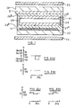
- FIG 1 is a schematic view of a liquid crystal display device disposed between two polarising plates 24, 25.
- the liquid crystal display device comprises a transparent substrate 22 on which are provided transparent strobe electrodes S (also known as row or scanning electrodes) which extend parallel to one another.
- An insulating layer 26a is provided over the strobe electrodes S, and an alignment film 27a is formed over the insulating layer.
- the alignment film 27a is spaced from a second alignment film 27b by spacers 28 and a liquid crystal layer 21.
- a second transparent substrate 23 carries transparent data electrodes D (also known as column electrodes), which are parallel to one another and which are perpendicular to the strobe electrodes.
- the alignment film 27b is formed over a second insulating layer 26b which itself is formed over the data electrodes D.
- the electrodes D, S are connected to a drive circuit (not shown).
- a pixel Pij is defined by the overlap of the ith strobe electrode and the jth data electrode.
- the pixel Pij is addressed by applying a strobe voltage to the ith strobe electrode while applying a data voltage to the jth data electrode. The voltage across the pixel is equal to the difference between the strobe voltage and the data voltage.
- One example of the voltages that can be used in a method of passively addressing a liquid crystal display are the Joers/Alvey voltage waveforms (P.W.H. Surguy et al, "Ferroelectrics” 122 pp 63-79 (1991)). These voltages are used to drive a display device comprising a layer of a ferroelectric liquid crystal (FLC) material which has two stable states - the drive voltage applied across a pixel will either switch the liquid crystal molecules in that pixel from one stable state to the other stable state, or it will not switch the liquid crystal molecules in that pixel.
- FLC ferroelectric liquid crystal
- FIGs 2(a)-2(d) One example of driving voltages according to the Joers/Alvey scheme is shown in Figures 2(a)-2(d).
- a strobe driving circuit (not shown in Figure 1) will apply a 'select' voltage pulse Vs shown in Fig. 2(a) to one strobe electrode, while applying the 'non-select' voltage pulse Vn (Fig 2(b)) to the remaining strobe electrodes.
- the pixels in the selected row of the display are addressed by a data driving circuit (not shown in Figure 1), which will apply either the 're-write' data voltage pulse V R (Fig 2(c)) or the 'hold' data voltage pulse V H (Fig 2(d)) to the column electrodes.
- a pixel to which is applied the 'select' strobe voltage and the 'switch' data voltage will switch from one stable state of the FLC to the other stable state, and all other pixels will not switch.
- the column electrodes can be addressed sequentially or simultaneously After one row of pixels has been addressed, the remaining rows are addressed, one after the other, in the same way.
- a conventional passively addressed liquid crystal display such as that shown in Figure 1, could be operated in such a way that two rows of pixels were simultaneously addressed by applying a first select voltage Vs1 to one strobe electrode and a second select voltage Vs2 to another strobe electrode.
- this driving method would require four different data voltages. This is because two binary pixels (that is, two pixels each of which has two possible display states) together give four possible combined display states (the two states of each pixel are shown as 1 and 0).
- the line address time increases substantially and becomes approximately equal to twice the line address time where the pixels are addressed one row at a time. Accordingly, there is no substantial improvement in the frame rate of which the display is capable. Further, this technique has the disadvantage of doubling the number of distinct data voltages required. In general, the maximum number of possible combined display states for a column of pixels is equal to the number N of different data voltage waveforms that the data driving circuit can supply.
- JP-A-06 120 324 discloses a device in which a pixel is 'split' into three 'sub-pixels', with each sub-pixel having a separate scanning electrode. This is to provide a grey-scale display, by providing intermediate display states in which part of the pixel blocks light and part of the pixel transmits light.
- JP-A-3 206 188 and JP-A-3 206 189 Other devices in which a pixel comprises two sub-pixels each having its own scanning electrode are disclosed in JP-A-3 206 188 and JP-A-3 206 189. It is again not possible to address the two sub-pixels completely independently from one another in these prior art devices.
- a display device comprising a plurality of strobe electrodes characterised by:
- a method of addressing a display device of the type comprising a plurality of strobe electrodes and a plurality of data electrodes crossed with the strobe electrodes to define a respective pixel at each overlap of one of the strobe electrodes with one of the pairs of data electrodes, the method comprising the steps of:
- the X pixels addressed by each group of strobe electrodes and each pair of data electrodes may have M combinations of optical states
- the data signal source may be arranged to supply any one of N data signals to a first data electrode of each pair and simultaneously to supply any one of the N data signals to a second data electrode of each pair and M may be greater than N.
- Such an arrangement allows the display device to display more combined display states than the number of data signals that the data signal source can supply. This enables the number of data signals that are required to drive, for instance, two rows of pixels simultaneously to be reduced.
- X may be equal to two and the strobe signal source may be arranged to supply a first strobe signal to each first strobe electrode of the groups and a second strobe signal, which is of the same waveform and amplitude as but of polarity opposite that of the first strobe signal, to each second strobe signal of the groups.
- Such an arrangement allows the strobe signal source to be simplified. In particular, half the number of strobe signal drivers are required as compared with conventional strobe signal sources which strobe each row in turn. The other drivers which would conventionally be required can be replaced by inverters so that the cost and complexity of the strobe signal source may be reduced.
- the data signal source may apply, in use, either a first data signal or a second data signal to the first data electrode and may simultaneously apply either a third data signal or the second data signal to the second data electrode and M may be equal to four.
- the second data signal may be a zero voltage. This enables the data signal source to be simplified, as only two non-zero voltage waveforms are required.
- Each pixel may be switchable between a first optical state and a second optical state. As two binary pixels can provide four different combined display states, these embodiments of the invention allow two rows of binary pixels to be driven simultaneously using only three data signals.
- the display device may be a diffractive spatial light modulator, and in the first optical state a pixel may diffract light and in the second optical state a pixel may transmit light or specularly reflect light.
- a modulator can have high resolution picture element and a display device having such a modulator has good reliability, a long life, and provides an image having good contrast and high intensity.
- Each pair of data electrodes may comprise a plurality of elongate parallel first electrode portions and a plurality of elongate parallel second electrode portions interdigitated with the first electrode portions.
- the display device may be a liquid crystal display device.
- FIGs 3 and 4 show a reflection-mode diffractive spatial light modulator (SLM).
- the SLM comprises a rectangular array of rectangular or substantially rectangular picture elements (pixels), only one of which is shown in Figures 3 and 4.
- the SLM comprises upper and lower glass substrates 1 and 2.
- the upper substrate 1 is coated with a transparent conducting layer of indium tin oxide (ITO) which is etched to form elongate interdigitated electrodes 3.
- the electrodes 3 are covered with an alignment layer 4 for a ferroelectric liquid crystal material.
- the alignment layer 4 is formed by obliquely evaporating silicon oxide at 84 degrees to the normal to the substrate 1 so as to induce the C1 state in a ferroelectric liquid crystal material, for instance of the type known as SCE8 available from Merck.
- the alignment layer 4 may have a thickness of approximately 10 nanometres.
- a combined mirror and electrode 5 is formed on the glass substrate 2 by depositing silver to a thickness of approximately 100 nanometres.
- a static quarter wave plate 6 is formed on the silver mirror and electrode 5.
- the quarter wave plate 6 may be provided by spinning on a mixture of a reactive mesogen RM257 in a suitable solvent such as a toluene/xylene mixture with a photoinitiator. This is cured for approximately ten minutes under ultraviolet light in an atmosphere of nitrogen.
- the thickness of the plate 6 is controlled, for instance by varying the mix ratios of the materials and the spin speed, so that it acts as a quarter wave plate for a predetermined bandwidth in the visible spectrum, for instance centred about 520 nanometres.
- the quarter wave plate 6 therefore typically has a thickness of the order of 800 nanometres.
- a further alignment layer 7 is formed on the quarter wave plate 6, for instance as described hereinbefore for the alignment layer 4.
- the substrates 1 and 2 are then spaced apart, for instance by spacer balls of two micrometre diameter, and stuck together so as to form a cell which is filled with the ferroelectric liquid crystal material to form a layer 8.
- the spacing provides a layer of ferroelectric liquid crystal material which provides a half wave of retardation so that the liquid crystal layer acts as a half wave retarder whose optic axis is switchable as described hereinafter.
- the reflectivity of each interface should preferably be reduced, for instance by applying anti-reflection coatings to the substrate 1 and by optically burying the electrodes 3.
- the electrodes 3 and 5 are arranged to provide for suitable addressing of the pixels of the SLM.
- the electrodes 3 may extend throughout the length of the SLM and may be connected to the outputs of a data signal generator for supplying a row of pixel data at a time to the pixels.
- the electrode 5 may be extended transversely to form a row electrode connected to the output of a strobe signal generator for strobing the data to the SLM a row at a time in a repeating sequence.
- the electrode 5 acts as a common electrode which is connectable to a reference voltage line, for instance supplying zero volts, for strobing data to be displayed at the pixel.
- Alternate ones of the elongate electrodes 3 are connected together to form two sets of interdigitated electrodes which are connected to receive suitable data signals.
- Each pixel is switchable between a reflective state and a diffractive state as described hereinafter.
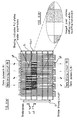
- Figure 5 illustrates diagrammatically the operation of adjacent strips of the pixel shown in Figures 3 and 4 when the pixel is in the diffractive mode.
- the optical path through each pixel is folded by reflection at the mirror 5 but, for the sake of clarity, the path is shown unfolded in Figure 5.
- the SLM acts on unpolarised light, which may be split into components of orthogonal polarisations for the sake of describing operation of the SLM.
- One of the component polarisations is shown at 10 in Figure 5 and is at an angle - ⁇ with respect to a predetermined direction 11.
- ferroelectric liquid crystal material strips 8a and 8b disposed between the electrodes 3a and 3b and the electrode 5 have optic axes aligned at angles of - ⁇ and + ⁇ , respectively, with respect to the direction 11, where ⁇ is preferably approximately equal to 22.5 degrees.
- Each strip 8a of ferroelectric liquid crystal material acts a half wave retarder so that the polarisation of the light component leaving the strip 8a is at an angle of ⁇ -2 ⁇ with respect to the direction 11.
- the light component then passes through the static quarter wave plate 6, is reflected by the mirror 5, and again passes through the static quarter wave plate 6, so that the combination of the quarter wave plate 6 and the mirror 5 acts as a half wave retarder whose optic axis is parallel to the direction 11.
- the polarisation direction of light leaving the quarter wave plate 6 and travelling towards the ferroelectric liquid crystal material is "reflected" about the optic axis of the quarter wave plate 6 and thus forms an angle 2 ⁇ - ⁇ with respect to the direction 11.
- the light component then again passes through the strip 8a of ferroelectric liquid crystal material so that the output polarisation as shown at 14 is at an angle of ⁇ -4 ⁇ with respect to the direction 11.
- the optical path through the SLM via each of the strips 8a of ferroelectric liquid crystal material is such that the polarisation direction is rotated by -4 ⁇ .
- This optical path therefore rotates the polarisation of unpolarised light by -4 ⁇ , which is substantially equal to -90 degrees.
- Each strip 8b of ferroelectric liquid crystal material acts as a half wave retarder and rotates the polarisation direction to ⁇ +2 ⁇ .
- the fixed half wave retarder formed by the combination of the quarter wave plate 6 and the mirror 5 rotates the direction of polarisation of the light component so that it makes an angle of -2 ⁇ - ⁇ with respect to the direction 11.
- the final passage through the strip 8b rotates the polarisation direction to ⁇ +4 ⁇ as shown at 15.
- unpolarised light passing through the strips 8b has its polarisation rotated by +4 ⁇ , which is substantially equal to +90 degrees.
- each of the strips 8b is out of phase by 180 degrees with respect to light passing through each of the strips 8a when the electrodes 3b and 3a are connected to receive data signals of opposite polarity.
- the pixel acts as a phase-only diffraction grating and the pixel operates in the diffractive mode. Because of the bi-stable characteristics of ferroelectric liquid crystals, it is necessary only to supply the data signals in order to switch the strips 8a and 8b to the different modes illustrated in Figure 5.
- each pixel is therefore switchable between a transmissive mode, in which light is specularly reflected or "deflected" into the zeroth diffraction order, and a diffractive mode, in which light incident on the pixel is deflected into the non-zero diffractive orders.
- This diffractive SLM is further described in GB 2 312 920 and EP 0 811 872.
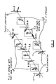
- FIG 6(a) is a schematic plan view of the SLM of Figures 3-5.
- Each pixel has a column electrode which consists of two sets of interdigitated electrodes 3a, 3b. These are driven by data driving circuits 29, 30.
- a strobe driving circuit 31 applies strobe voltages to the row electrodes.
- the input to one set of electrodes 3a can be either of two voltage pulses A or B
- the input to the other set of electrodes 3b can be either of two voltage pulses C or D.
- the column electrode of a pixel is made up of the two interdigitated electrodes, there are now four possible inputs to the column electrode of a pixel - A to one electrode and C to the other electrode (AC), A to one electrode and D to the other electrode (AD), B to one electrode and C to the other electrode (BC) or B to one electrode and D to the other electrode (BD).
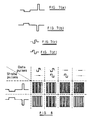
- the second 'select' strobe voltage is a voltage pulse Vs2 which is equal in magnitude but opposite in polarity to the first 'select' strobe voltage Vs1.
- the voltage pulses S1 and S2 are shown in Figures 7(a) and 7(b) respectively.
- the usual data pulses used in the J-A scheme are opposite polarity, two slot bipolar pulses which, when applied to the jth data electrode at the same time as a strobe voltage pulse is applied to the ith row electrode, will produce a voltage across pixel P ij that either switches or does not switch the FLC.
- These known data voltage pulses can be chosen as part of the addressing set (voltage pulses A and C referred to above) since they offer known switching discrimination. By their nature, they act in an opposite manner on the FLC when combined with the opposite polarity strobe pulses.
- one of the data pulses, A, ( Figure 7(c)) would completely switch the FLC with one strobe pulse S1, and would not switch the FLC with the other strobe pulse S2 (and vice versa for the other data pulse, C ( Figure 7(d)).
- a suitable third data pulse, B must be chosen that has no FLC switching discrimination when combined with either of the strobe pulses. That is, the data pulse B would have the same switching effect on the FLC with either of the strobe pulses S1 or S2.
- Such a data pulse could be a zero voltage pulse which can be made either to switch the FLC for either strobe pulse or, more favourably (in terms of overall panel address time), not to switch the FLC for either strobe pulse.
- Figure 8 the voltage pulses are shown together with the states (indicated by black or white) of the FLC under the interdigitated electrodes. Where the FLC under one column electrode 3a and the FLC under the other column electrode 3b are in different states, a diffraction grating is set up and the pixel can be considered ON; when the FLC under one column electrode 3a and the FLC under the other column electrode 3b are in the same state, the pixel is OFF. (It should be noted that the use of black and white in Figure 8 does not mean that the liquid crystal blocks light in the areas shaded in black and transmits light in the regions shown in white. This also applies to Figure 6(a). The pixels are shown in Figure 6(b) as they would appear to an observer.)
- This display can operate with no increase in slot time compared to the usual addressing scheme. This means in principle that the frame rate should be doubled by using this addressing technique over conventional panels. Since the size of projection panels is small and they are typically operated within a controlled environment, device tolerances can be reduced allowing full benefit of the increased addressing rate.
- FLC based embodiments of the present invention could use extensions of other known addressing schemes, for example such as the Malvern -3 addressing method (J.R. Hughes and E.P. Raynes, "Liquid Crystals” 13 pp597-601, 1993).
- the C2 liquid crystal alignment is used.
- the alignment layers 27a and 27b comprise low pretilt polyimide alignment layers, for example formed by spin-coating PI2555 (available from Dupont) to a depth of approximately 100 nanometres or less.
- the ferroelectric liquid crystal of the layer 21 has a chiral smectic C phase, a ⁇ -Vmin characteristic, spontaneous polarisation less than 20nC/cm 2 , a cone angle of between 10° and 45° and preferably of 22.5°, and positive dielectric biaxiality.
- This embodiment may use a quarter cycle, phase shifted bipolar signal similar to the two slot data pulses.
- the voltage there are again constraints on the voltage as its associated switching curve would bisect the conventional data switching curves, as in the zero volt case.
- stabilising would be improved as the RMS a.c. voltage across the FLC would be maintained.
- Good stabilisation improves the brightness of a diffractive SLM panel as it increases the switching angle which, for currently available addressable materials, is typically found to be lower than the ideal angle (45°).
- the data pulses provide an a.c. waveform at the non-selected rows and this causes the FLC to be driven to a higher angle state closer to the cone angle of the material. This may be beneficial in achieving the required switched angle for maximising light throughput.
- FLC embodiments could include an alternative non-discriminating data voltage pulse (i.e., voltage B), such as a higher frequency, high voltage bipolar voltage signal.
- voltage B non-discriminating data voltage pulse
- the switching curve would exist above the two curves associated with conventional addressing methods (due to increased a.c. stabilisation) and the improvement in the line address time would be expected to be a factor of two over the fundamental limit when employing strobe extension.
- the present invention is not limited to FLC displays.
- it can be applied to other liquid crystal displays such as a display having a super twisted nematic (STN) liquid crystal.
- STN super twisted nematic
- the three data voltages could simply be a positive pulse, a negative pulse, and a zero voltage pulse.
- the two strobe pulses would be of opposite polarity to one another.
- the four possible display states of two pixels would be generated as follows:
- liquid crystal portions under one column electrode in a pixel are in a different state from liquid crystal portions under the second column electrode, a diffraction grating is set up and the pixel is 'ON' (light is diffracted out and can be used to display an image). If the liquid crystal portions under the two column electrodes are in the same state, then there is no diffraction grating and so the pixel is 'OFF'.
- AFLC anti-ferroelectric liquid crystal
- This mode has similar optical characteristics to the FLC mode described hereinbefore and is capable of achieving analogue or grey level operation through domain growth.
- a possible passive AFLC addressing mode uses resetting to the pair of ferroelectric states to provide equivalence to the FLC operation.
- a modulator of the type described hereinbefore may also be embodied using a bistable twisted nematic (BTN) liquid crystal in an active matrix addressing arrangement.
- BTN bistable twisted nematic
- For approximately twice the cell gap in an anti-parallel aligned cell produces a splayed 180° twist state and two splayed metastable states with 0° and 360° twist.
- the two metastable states provide a bistable mode of operation for the liquid crystal.
- the liquid crystal can be switched between the metastable states by applying a reset pulse, which produces a temporary homeotropic state.
- the metastable states may be rapidly accessed and represent the bistable states.
- Two-line addressing of such a BTN mode modulator can be performed similarly to the STN mode described hereinbefore with the reset pulse on both rows restoring an OFF state.
- the method of this invention is not limited to liquid crystal displays, but it can be applied to other passively addressed, pixelated display devices in which a pixel has two independent column electrodes.
- it could be applied, in principle, to the 'Deformable Grating Light Valve' disclosed in SID 1993, pp 807-8, Apte et al.
Landscapes
- Physics & Mathematics (AREA)
- Engineering & Computer Science (AREA)
- Chemical & Material Sciences (AREA)
- Crystallography & Structural Chemistry (AREA)
- General Physics & Mathematics (AREA)
- Computer Hardware Design (AREA)
- Theoretical Computer Science (AREA)
- Nonlinear Science (AREA)
- Optics & Photonics (AREA)
- Liquid Crystal Display Device Control (AREA)
- Liquid Crystal (AREA)
- Control Of Indicators Other Than Cathode Ray Tubes (AREA)
Applications Claiming Priority (2)
| Application Number | Priority Date | Filing Date | Title |
|---|---|---|---|
| GB9721819 | 1997-10-16 | ||
| GB9721819A GB2330678A (en) | 1997-10-16 | 1997-10-16 | Addressing a ferroelectric liquid crystal display |
Publications (1)
| Publication Number | Publication Date |
|---|---|
| EP0911794A1 true EP0911794A1 (en) | 1999-04-28 |
Family
ID=10820570
Family Applications (1)
| Application Number | Title | Priority Date | Filing Date |
|---|---|---|---|
| EP98308186A Withdrawn EP0911794A1 (en) | 1997-10-16 | 1998-10-08 | Display device and method of addressing the same with simultaneous addressing of groups of strobe electrodes and pairs of data electrodes in combination |
Country Status (5)
| Country | Link |
|---|---|
| US (1) | US6281866B1 (enExample) |
| EP (1) | EP0911794A1 (enExample) |
| JP (1) | JP3838792B2 (enExample) |
| KR (1) | KR100354631B1 (enExample) |
| GB (1) | GB2330678A (enExample) |
Cited By (40)
| Publication number | Priority date | Publication date | Assignee | Title |
|---|---|---|---|---|
| US7136213B2 (en) | 2004-09-27 | 2006-11-14 | Idc, Llc | Interferometric modulators having charge persistence |
| US7142346B2 (en) | 2003-12-09 | 2006-11-28 | Idc, Llc | System and method for addressing a MEMS display |
| US7196837B2 (en) | 2003-12-09 | 2007-03-27 | Idc, Llc | Area array modulation and lead reduction in interferometric modulators |
| US7310179B2 (en) | 2004-09-27 | 2007-12-18 | Idc, Llc | Method and device for selective adjustment of hysteresis window |
| US7345805B2 (en) | 2004-09-27 | 2008-03-18 | Idc, Llc | Interferometric modulator array with integrated MEMS electrical switches |
| US7355779B2 (en) | 2005-09-02 | 2008-04-08 | Idc, Llc | Method and system for driving MEMS display elements |
| US7388706B2 (en) | 1995-05-01 | 2008-06-17 | Idc, Llc | Photonic MEMS and structures |
| US7446927B2 (en) | 2004-09-27 | 2008-11-04 | Idc, Llc | MEMS switch with set and latch electrodes |
| US7471444B2 (en) | 1996-12-19 | 2008-12-30 | Idc, Llc | Interferometric modulation of radiation |
| US7486429B2 (en) | 2004-09-27 | 2009-02-03 | Idc, Llc | Method and device for multistate interferometric light modulation |
| US7499208B2 (en) | 2004-08-27 | 2009-03-03 | Udc, Llc | Current mode display driver circuit realization feature |
| US7515147B2 (en) | 2004-08-27 | 2009-04-07 | Idc, Llc | Staggered column drive circuit systems and methods |
| US7532195B2 (en) | 2004-09-27 | 2009-05-12 | Idc, Llc | Method and system for reducing power consumption in a display |
| US7545550B2 (en) | 2004-09-27 | 2009-06-09 | Idc, Llc | Systems and methods of actuating MEMS display elements |
| US7551159B2 (en) | 2004-08-27 | 2009-06-23 | Idc, Llc | System and method of sensing actuation and release voltages of an interferometric modulator |
| US7560299B2 (en) | 2004-08-27 | 2009-07-14 | Idc, Llc | Systems and methods of actuating MEMS display elements |
| US7602375B2 (en) | 2004-09-27 | 2009-10-13 | Idc, Llc | Method and system for writing data to MEMS display elements |
| US7626581B2 (en) | 2004-09-27 | 2009-12-01 | Idc, Llc | Device and method for display memory using manipulation of mechanical response |
| US7675669B2 (en) | 2004-09-27 | 2010-03-09 | Qualcomm Mems Technologies, Inc. | Method and system for driving interferometric modulators |
| US7679627B2 (en) | 2004-09-27 | 2010-03-16 | Qualcomm Mems Technologies, Inc. | Controller and driver features for bi-stable display |
| US7702192B2 (en) | 2006-06-21 | 2010-04-20 | Qualcomm Mems Technologies, Inc. | Systems and methods for driving MEMS display |
| US7724993B2 (en) | 2004-09-27 | 2010-05-25 | Qualcomm Mems Technologies, Inc. | MEMS switches with deforming membranes |
| US7777715B2 (en) | 2006-06-29 | 2010-08-17 | Qualcomm Mems Technologies, Inc. | Passive circuits for de-multiplexing display inputs |
| US7843410B2 (en) | 2004-09-27 | 2010-11-30 | Qualcomm Mems Technologies, Inc. | Method and device for electrically programmable display |
| US7889163B2 (en) | 2004-08-27 | 2011-02-15 | Qualcomm Mems Technologies, Inc. | Drive method for MEMS devices |
| US7920136B2 (en) | 2005-05-05 | 2011-04-05 | Qualcomm Mems Technologies, Inc. | System and method of driving a MEMS display device |
| US7948457B2 (en) | 2005-05-05 | 2011-05-24 | Qualcomm Mems Technologies, Inc. | Systems and methods of actuating MEMS display elements |
| US7957589B2 (en) | 2007-01-25 | 2011-06-07 | Qualcomm Mems Technologies, Inc. | Arbitrary power function using logarithm lookup table |
| US8049713B2 (en) | 2006-04-24 | 2011-11-01 | Qualcomm Mems Technologies, Inc. | Power consumption optimized display update |
| US8174469B2 (en) | 2005-05-05 | 2012-05-08 | Qualcomm Mems Technologies, Inc. | Dynamic driver IC and display panel configuration |
| US8194056B2 (en) | 2006-02-09 | 2012-06-05 | Qualcomm Mems Technologies Inc. | Method and system for writing data to MEMS display elements |
| US8310441B2 (en) | 2004-09-27 | 2012-11-13 | Qualcomm Mems Technologies, Inc. | Method and system for writing data to MEMS display elements |
| US8391630B2 (en) | 2005-12-22 | 2013-03-05 | Qualcomm Mems Technologies, Inc. | System and method for power reduction when decompressing video streams for interferometric modulator displays |
| US8405649B2 (en) | 2009-03-27 | 2013-03-26 | Qualcomm Mems Technologies, Inc. | Low voltage driver scheme for interferometric modulators |
| US8514169B2 (en) | 2004-09-27 | 2013-08-20 | Qualcomm Mems Technologies, Inc. | Apparatus and system for writing data to electromechanical display elements |
| US8736590B2 (en) | 2009-03-27 | 2014-05-27 | Qualcomm Mems Technologies, Inc. | Low voltage driver scheme for interferometric modulators |
| US8878825B2 (en) | 2004-09-27 | 2014-11-04 | Qualcomm Mems Technologies, Inc. | System and method for providing a variable refresh rate of an interferometric modulator display |
| US8928967B2 (en) | 1998-04-08 | 2015-01-06 | Qualcomm Mems Technologies, Inc. | Method and device for modulating light |
| US8971675B2 (en) | 2006-01-13 | 2015-03-03 | Qualcomm Mems Technologies, Inc. | Interconnect structure for MEMS device |
| US9110289B2 (en) | 1998-04-08 | 2015-08-18 | Qualcomm Mems Technologies, Inc. | Device for modulating light with multiple electrodes |
Families Citing this family (9)
| Publication number | Priority date | Publication date | Assignee | Title |
|---|---|---|---|---|
| JP3559719B2 (ja) * | 1998-01-13 | 2004-09-02 | キヤノン株式会社 | プラズマアドレス型の液晶表示装置 |
| US6600467B1 (en) * | 1999-04-28 | 2003-07-29 | Homer L. Webb | Flat panel display architecture |
| KR100546606B1 (ko) * | 2003-05-14 | 2006-01-26 | 엘지전자 주식회사 | 반사형 조명 광학계 |
| US7019879B2 (en) * | 2004-03-26 | 2006-03-28 | Schroeder Dale W | Angled strobe lines for high aspect ratio spatial light modulator |
| US20070050242A1 (en) * | 2005-08-23 | 2007-03-01 | Way Out World, Llc | Solo-unit system and methods for game augmented interactive marketing |
| JP2008129482A (ja) * | 2006-11-24 | 2008-06-05 | Nec Lcd Technologies Ltd | 液晶表示装置及びその製造方法 |
| US8659510B2 (en) * | 2008-12-16 | 2014-02-25 | Hewlett-Packard Development Company, L.P. | Spatial light modulator |
| CN102439516B (zh) * | 2010-01-20 | 2013-01-23 | 深圳超多维光电子有限公司 | 扭曲向列液晶盒及包含该液晶盒的2d-3d立体显示装置 |
| CN103180780B (zh) * | 2010-10-22 | 2017-09-22 | 瑞尔D股份有限公司 | 分割分段式液晶调制器 |
Citations (3)
| Publication number | Priority date | Publication date | Assignee | Title |
|---|---|---|---|---|
| US5182665A (en) * | 1990-09-07 | 1993-01-26 | Displaytech, Inc. | Diffractive light modulator |
| EP0526095A2 (en) * | 1991-07-24 | 1993-02-03 | Canon Kabushiki Kaisha | Displaying information |
| US5648792A (en) * | 1994-03-14 | 1997-07-15 | Hitachi, Ltd. | Liquid crystal display device having a thin film |
Family Cites Families (13)
| Publication number | Priority date | Publication date | Assignee | Title |
|---|---|---|---|---|
| US5077553A (en) * | 1988-01-19 | 1991-12-31 | Tektronix, Inc. | Apparatus for and methods of addressing data storage elements |
| US4896149A (en) * | 1988-01-19 | 1990-01-23 | Tektronix, Inc. | Addressing structure using ionizable gaseous medium |
| JPH03206188A (ja) | 1989-12-29 | 1991-09-09 | Suzutora Seisen Kojo:Kk | 繊維布帛に柄模様を形成する方法 |
| JP3011371B2 (ja) | 1989-12-30 | 2000-02-21 | 三英ケミカル株式会社 | 熱反転式植毛転写生地及びその製造法 |
| US5485173A (en) * | 1991-04-01 | 1996-01-16 | In Focus Systems, Inc. | LCD addressing system and method |
| JPH06120324A (ja) | 1992-03-13 | 1994-04-28 | Ratsupu Master S F T Kk | 半導体ウエハの位置決め機構 |
| GB2295478B (en) * | 1992-07-07 | 1996-11-13 | Seiko Epson Corp | Matrix displays |
| JP2847666B2 (ja) * | 1993-03-04 | 1999-01-20 | テクトロニクス・インコーポレイテッド | 電気光学表示方法 |
| US5614924A (en) * | 1994-06-01 | 1997-03-25 | Sharp Kabushiki Kaisha | Ferroelectric liquid crystal display device and a driving method of effecting gradational display therefor |
| GB2293906A (en) * | 1994-10-03 | 1996-04-10 | Sharp Kk | Liquid crystal display |
| GB2294797A (en) * | 1994-11-01 | 1996-05-08 | Sharp Kk | Method of addressing a liquid crystal display |
| GB2312920B (en) | 1996-05-08 | 1999-10-27 | Thomas Keith Brown | Security devices |
| GB2313920A (en) | 1996-06-07 | 1997-12-10 | Sharp Kk | Diffractive spatial light modulator and display |
-
1997
- 1997-10-16 GB GB9721819A patent/GB2330678A/en not_active Withdrawn
-
1998
- 1998-10-08 EP EP98308186A patent/EP0911794A1/en not_active Withdrawn
- 1998-10-09 US US09/169,641 patent/US6281866B1/en not_active Expired - Fee Related
- 1998-10-14 JP JP29263598A patent/JP3838792B2/ja not_active Expired - Fee Related
- 1998-10-15 KR KR1019980043193A patent/KR100354631B1/ko not_active Expired - Fee Related
Patent Citations (3)
| Publication number | Priority date | Publication date | Assignee | Title |
|---|---|---|---|---|
| US5182665A (en) * | 1990-09-07 | 1993-01-26 | Displaytech, Inc. | Diffractive light modulator |
| EP0526095A2 (en) * | 1991-07-24 | 1993-02-03 | Canon Kabushiki Kaisha | Displaying information |
| US5648792A (en) * | 1994-03-14 | 1997-07-15 | Hitachi, Ltd. | Liquid crystal display device having a thin film |
Cited By (51)
| Publication number | Priority date | Publication date | Assignee | Title |
|---|---|---|---|---|
| US7388706B2 (en) | 1995-05-01 | 2008-06-17 | Idc, Llc | Photonic MEMS and structures |
| US7471444B2 (en) | 1996-12-19 | 2008-12-30 | Idc, Llc | Interferometric modulation of radiation |
| US9110289B2 (en) | 1998-04-08 | 2015-08-18 | Qualcomm Mems Technologies, Inc. | Device for modulating light with multiple electrodes |
| US8928967B2 (en) | 1998-04-08 | 2015-01-06 | Qualcomm Mems Technologies, Inc. | Method and device for modulating light |
| US7242512B2 (en) | 2003-12-09 | 2007-07-10 | Idc, Llc | System and method for addressing a MEMS display |
| US7388697B2 (en) | 2003-12-09 | 2008-06-17 | Idc, Llc | System and method for addressing a MEMS display |
| US7196837B2 (en) | 2003-12-09 | 2007-03-27 | Idc, Llc | Area array modulation and lead reduction in interferometric modulators |
| US7142346B2 (en) | 2003-12-09 | 2006-11-28 | Idc, Llc | System and method for addressing a MEMS display |
| US7889163B2 (en) | 2004-08-27 | 2011-02-15 | Qualcomm Mems Technologies, Inc. | Drive method for MEMS devices |
| US7928940B2 (en) | 2004-08-27 | 2011-04-19 | Qualcomm Mems Technologies, Inc. | Drive method for MEMS devices |
| US7551159B2 (en) | 2004-08-27 | 2009-06-23 | Idc, Llc | System and method of sensing actuation and release voltages of an interferometric modulator |
| US7852542B2 (en) | 2004-08-27 | 2010-12-14 | Qualcomm Mems Technologies, Inc. | Current mode display driver circuit realization feature |
| US7499208B2 (en) | 2004-08-27 | 2009-03-03 | Udc, Llc | Current mode display driver circuit realization feature |
| US7515147B2 (en) | 2004-08-27 | 2009-04-07 | Idc, Llc | Staggered column drive circuit systems and methods |
| US7560299B2 (en) | 2004-08-27 | 2009-07-14 | Idc, Llc | Systems and methods of actuating MEMS display elements |
| US7446927B2 (en) | 2004-09-27 | 2008-11-04 | Idc, Llc | MEMS switch with set and latch electrodes |
| US7843410B2 (en) | 2004-09-27 | 2010-11-30 | Qualcomm Mems Technologies, Inc. | Method and device for electrically programmable display |
| US7532195B2 (en) | 2004-09-27 | 2009-05-12 | Idc, Llc | Method and system for reducing power consumption in a display |
| US7602375B2 (en) | 2004-09-27 | 2009-10-13 | Idc, Llc | Method and system for writing data to MEMS display elements |
| US7626581B2 (en) | 2004-09-27 | 2009-12-01 | Idc, Llc | Device and method for display memory using manipulation of mechanical response |
| US7667884B2 (en) | 2004-09-27 | 2010-02-23 | Qualcomm Mems Technologies, Inc. | Interferometric modulators having charge persistence |
| US7675669B2 (en) | 2004-09-27 | 2010-03-09 | Qualcomm Mems Technologies, Inc. | Method and system for driving interferometric modulators |
| US7679627B2 (en) | 2004-09-27 | 2010-03-16 | Qualcomm Mems Technologies, Inc. | Controller and driver features for bi-stable display |
| US7486429B2 (en) | 2004-09-27 | 2009-02-03 | Idc, Llc | Method and device for multistate interferometric light modulation |
| US7724993B2 (en) | 2004-09-27 | 2010-05-25 | Qualcomm Mems Technologies, Inc. | MEMS switches with deforming membranes |
| US8878771B2 (en) | 2004-09-27 | 2014-11-04 | Qualcomm Mems Technologies, Inc. | Method and system for reducing power consumption in a display |
| US7545550B2 (en) | 2004-09-27 | 2009-06-09 | Idc, Llc | Systems and methods of actuating MEMS display elements |
| US8310441B2 (en) | 2004-09-27 | 2012-11-13 | Qualcomm Mems Technologies, Inc. | Method and system for writing data to MEMS display elements |
| US7345805B2 (en) | 2004-09-27 | 2008-03-18 | Idc, Llc | Interferometric modulator array with integrated MEMS electrical switches |
| US8878825B2 (en) | 2004-09-27 | 2014-11-04 | Qualcomm Mems Technologies, Inc. | System and method for providing a variable refresh rate of an interferometric modulator display |
| US7310179B2 (en) | 2004-09-27 | 2007-12-18 | Idc, Llc | Method and device for selective adjustment of hysteresis window |
| US8791897B2 (en) | 2004-09-27 | 2014-07-29 | Qualcomm Mems Technologies, Inc. | Method and system for writing data to MEMS display elements |
| US8514169B2 (en) | 2004-09-27 | 2013-08-20 | Qualcomm Mems Technologies, Inc. | Apparatus and system for writing data to electromechanical display elements |
| US8471808B2 (en) | 2004-09-27 | 2013-06-25 | Qualcomm Mems Technologies, Inc. | Method and device for reducing power consumption in a display |
| US8085461B2 (en) | 2004-09-27 | 2011-12-27 | Qualcomm Mems Technologies, Inc. | Systems and methods of actuating MEMS display elements |
| US7136213B2 (en) | 2004-09-27 | 2006-11-14 | Idc, Llc | Interferometric modulators having charge persistence |
| US8344997B2 (en) | 2004-09-27 | 2013-01-01 | Qualcomm Mems Technologies, Inc. | Method and system for writing data to electromechanical display elements |
| US8243014B2 (en) | 2004-09-27 | 2012-08-14 | Qualcomm Mems Technologies, Inc. | Method and system for reducing power consumption in a display |
| US8174469B2 (en) | 2005-05-05 | 2012-05-08 | Qualcomm Mems Technologies, Inc. | Dynamic driver IC and display panel configuration |
| US7948457B2 (en) | 2005-05-05 | 2011-05-24 | Qualcomm Mems Technologies, Inc. | Systems and methods of actuating MEMS display elements |
| US7920136B2 (en) | 2005-05-05 | 2011-04-05 | Qualcomm Mems Technologies, Inc. | System and method of driving a MEMS display device |
| US7355779B2 (en) | 2005-09-02 | 2008-04-08 | Idc, Llc | Method and system for driving MEMS display elements |
| US8391630B2 (en) | 2005-12-22 | 2013-03-05 | Qualcomm Mems Technologies, Inc. | System and method for power reduction when decompressing video streams for interferometric modulator displays |
| US8971675B2 (en) | 2006-01-13 | 2015-03-03 | Qualcomm Mems Technologies, Inc. | Interconnect structure for MEMS device |
| US8194056B2 (en) | 2006-02-09 | 2012-06-05 | Qualcomm Mems Technologies Inc. | Method and system for writing data to MEMS display elements |
| US8049713B2 (en) | 2006-04-24 | 2011-11-01 | Qualcomm Mems Technologies, Inc. | Power consumption optimized display update |
| US7702192B2 (en) | 2006-06-21 | 2010-04-20 | Qualcomm Mems Technologies, Inc. | Systems and methods for driving MEMS display |
| US7777715B2 (en) | 2006-06-29 | 2010-08-17 | Qualcomm Mems Technologies, Inc. | Passive circuits for de-multiplexing display inputs |
| US7957589B2 (en) | 2007-01-25 | 2011-06-07 | Qualcomm Mems Technologies, Inc. | Arbitrary power function using logarithm lookup table |
| US8405649B2 (en) | 2009-03-27 | 2013-03-26 | Qualcomm Mems Technologies, Inc. | Low voltage driver scheme for interferometric modulators |
| US8736590B2 (en) | 2009-03-27 | 2014-05-27 | Qualcomm Mems Technologies, Inc. | Low voltage driver scheme for interferometric modulators |
Also Published As
| Publication number | Publication date |
|---|---|
| KR100354631B1 (ko) | 2002-11-18 |
| JP2000193940A (ja) | 2000-07-14 |
| US6281866B1 (en) | 2001-08-28 |
| KR19990037132A (ko) | 1999-05-25 |
| JP3838792B2 (ja) | 2006-10-25 |
| GB9721819D0 (en) | 1997-12-17 |
| GB2330678A (en) | 1999-04-28 |
Similar Documents
| Publication | Publication Date | Title |
|---|---|---|
| US6281866B1 (en) | Display device and a method of addressing a display device | |
| US6243063B1 (en) | Diffractive spatial light modulator and display | |
| US5594464A (en) | Liquid crystal display device having two metastable states and driving method therefor | |
| US7161573B1 (en) | Liquid crystal display unit and method for driving the same | |
| US6061042A (en) | Liquid crystal display device | |
| KR100300280B1 (ko) | 액티브 매트릭스 광 변조기 및 표시 장치 | |
| US20040141107A1 (en) | Liquid crystal device | |
| US6094249A (en) | Spatial light modulator and display with reduced electrical connectivity requirement | |
| KR20050014846A (ko) | 디스플레이 디바이스 | |
| US6201589B1 (en) | Spatial light modulator and display with picture elements having electrically floating electrodes | |
| US6104368A (en) | Diffractive liquid crystal device | |
| US5189535A (en) | Liquid crystal display element and method for driving same | |
| JP2001514399A (ja) | 双安定コレステリック液晶デバイスの駆動方法 | |
| EP0569029B1 (en) | Liquid crystal display device having two metastable states and its driving method | |
| KR20020032439A (ko) | 그레이 스케일을 얻기 위한 디스플레이 디바이스의 구동 | |
| US5638143A (en) | Ferroelectric liquid crystal display device with a particular angle between the polarizer optical axes and the molecular director | |
| JPH0764056A (ja) | 反強誘電性液晶表示素子及び反強誘電性液晶表示素子の駆動方法 | |
| JP3259600B2 (ja) | 反強誘電性液晶表示素子 | |
| GB2314423A (en) | Liquid crystal devices | |
| US20020093471A1 (en) | Display device | |
| JPS63195625A (ja) | 液晶表示素子の駆動方法 | |
| JPS614027A (ja) | 液晶素子の駆動法 | |
| JPH09236829A (ja) | 反強誘電性液晶表示素子およびその駆動方法 |
Legal Events
| Date | Code | Title | Description |
|---|---|---|---|
| PUAI | Public reference made under article 153(3) epc to a published international application that has entered the european phase |
Free format text: ORIGINAL CODE: 0009012 |
|
| AK | Designated contracting states |
Kind code of ref document: A1 Designated state(s): AT BE CH CY DE DK ES FI FR GB GR IE IT LI LU MC NL PT SE |
|
| AX | Request for extension of the european patent |
Free format text: AL;LT;LV;MK;RO;SI |
|
| AKX | Designation fees paid | ||
| REG | Reference to a national code |
Ref country code: DE Ref legal event code: 8566 |
|
| STAA | Information on the status of an ep patent application or granted ep patent |
Free format text: STATUS: THE APPLICATION IS DEEMED TO BE WITHDRAWN |
|
| 18D | Application deemed to be withdrawn |
Effective date: 19991029 |