EP0911624B1 - Procédé d'attaque thermique en conditions oxydantes d'une ceramique - Google Patents
Procédé d'attaque thermique en conditions oxydantes d'une ceramique Download PDFInfo
- Publication number
- EP0911624B1 EP0911624B1 EP98402583A EP98402583A EP0911624B1 EP 0911624 B1 EP0911624 B1 EP 0911624B1 EP 98402583 A EP98402583 A EP 98402583A EP 98402583 A EP98402583 A EP 98402583A EP 0911624 B1 EP0911624 B1 EP 0911624B1
- Authority
- EP
- European Patent Office
- Prior art keywords
- ceramic
- process according
- temperature
- attack
- thermal
- Prior art date
- Legal status (The legal status is an assumption and is not a legal conclusion. Google has not performed a legal analysis and makes no representation as to the accuracy of the status listed.)
- Expired - Lifetime
Links
- 238000000034 method Methods 0.000 title claims description 63
- 239000000919 ceramic Substances 0.000 title claims description 62
- 238000005530 etching Methods 0.000 title claims description 32
- 230000008569 process Effects 0.000 claims description 42
- 230000001590 oxidative effect Effects 0.000 claims description 34
- 229910052778 Plutonium Inorganic materials 0.000 claims description 32
- 229910052760 oxygen Inorganic materials 0.000 claims description 28
- 239000000126 substance Substances 0.000 claims description 27
- 230000003287 optical effect Effects 0.000 claims description 24
- QVGXLLKOCUKJST-UHFFFAOYSA-N atomic oxygen Chemical compound [O] QVGXLLKOCUKJST-UHFFFAOYSA-N 0.000 claims description 23
- 239000001301 oxygen Substances 0.000 claims description 23
- XKRFYHLGVUSROY-UHFFFAOYSA-N Argon Chemical compound [Ar] XKRFYHLGVUSROY-UHFFFAOYSA-N 0.000 claims description 22
- 239000007789 gas Substances 0.000 claims description 20
- 229910052770 Uranium Inorganic materials 0.000 claims description 18
- 238000005259 measurement Methods 0.000 claims description 18
- 229910052786 argon Inorganic materials 0.000 claims description 11
- 238000004458 analytical method Methods 0.000 claims description 10
- 239000000203 mixture Substances 0.000 claims description 10
- 239000003758 nuclear fuel Substances 0.000 claims description 9
- 238000005498 polishing Methods 0.000 claims description 7
- PNEYBMLMFCGWSK-UHFFFAOYSA-N aluminium oxide Inorganic materials [O-2].[O-2].[O-2].[Al+3].[Al+3] PNEYBMLMFCGWSK-UHFFFAOYSA-N 0.000 claims description 6
- 239000000843 powder Substances 0.000 claims description 6
- 238000004320 controlled atmosphere Methods 0.000 claims description 4
- 229910052751 metal Inorganic materials 0.000 claims description 4
- 239000002184 metal Substances 0.000 claims description 4
- 150000002739 metals Chemical class 0.000 claims description 4
- 229910052768 actinide Inorganic materials 0.000 claims description 2
- 150000001255 actinides Chemical class 0.000 claims description 2
- 229910000420 cerium oxide Inorganic materials 0.000 claims description 2
- DRVWBEJJZZTIGJ-UHFFFAOYSA-N cerium(3+);oxygen(2-) Chemical class [O-2].[O-2].[O-2].[Ce+3].[Ce+3] DRVWBEJJZZTIGJ-UHFFFAOYSA-N 0.000 claims description 2
- 239000011261 inert gas Substances 0.000 claims description 2
- 229910044991 metal oxide Inorganic materials 0.000 claims description 2
- 150000004706 metal oxides Chemical class 0.000 claims description 2
- 229910052776 Thorium Inorganic materials 0.000 claims 1
- 239000000523 sample Substances 0.000 description 29
- OYEHPCDNVJXUIW-UHFFFAOYSA-N plutonium atom Chemical compound [Pu] OYEHPCDNVJXUIW-UHFFFAOYSA-N 0.000 description 19
- 101710194180 Alcohol oxidase 1 Proteins 0.000 description 15
- 239000000446 fuel Substances 0.000 description 15
- 229910052739 hydrogen Inorganic materials 0.000 description 13
- 239000002245 particle Substances 0.000 description 11
- 101710194173 Alcohol oxidase 2 Proteins 0.000 description 10
- 238000003486 chemical etching Methods 0.000 description 8
- 239000001257 hydrogen Substances 0.000 description 8
- 239000000463 material Substances 0.000 description 8
- FCTBKIHDJGHPPO-UHFFFAOYSA-N uranium dioxide Inorganic materials O=[U]=O FCTBKIHDJGHPPO-UHFFFAOYSA-N 0.000 description 8
- UFHFLCQGNIYNRP-UHFFFAOYSA-N Hydrogen Chemical compound [H][H] UFHFLCQGNIYNRP-UHFFFAOYSA-N 0.000 description 7
- WZECUPJJEIXUKY-UHFFFAOYSA-N [O-2].[O-2].[O-2].[U+6] Chemical compound [O-2].[O-2].[O-2].[U+6] WZECUPJJEIXUKY-UHFFFAOYSA-N 0.000 description 7
- 239000002253 acid Substances 0.000 description 7
- 230000007547 defect Effects 0.000 description 7
- 238000005516 engineering process Methods 0.000 description 7
- 229910000439 uranium oxide Inorganic materials 0.000 description 7
- 239000008188 pellet Substances 0.000 description 6
- 239000012071 phase Substances 0.000 description 6
- 238000002360 preparation method Methods 0.000 description 6
- 238000009826 distribution Methods 0.000 description 5
- 239000011159 matrix material Substances 0.000 description 5
- JFALSRSLKYAFGM-UHFFFAOYSA-N uranium(0) Chemical compound [U] JFALSRSLKYAFGM-UHFFFAOYSA-N 0.000 description 5
- 238000002474 experimental method Methods 0.000 description 4
- 238000005245 sintering Methods 0.000 description 4
- 238000012360 testing method Methods 0.000 description 4
- 241001044053 Mimas Species 0.000 description 3
- 230000008901 benefit Effects 0.000 description 3
- 239000012159 carrier gas Substances 0.000 description 3
- 238000012937 correction Methods 0.000 description 3
- 230000007797 corrosion Effects 0.000 description 3
- 238000005260 corrosion Methods 0.000 description 3
- 238000010438 heat treatment Methods 0.000 description 3
- 238000010191 image analysis Methods 0.000 description 3
- 238000001000 micrograph Methods 0.000 description 3
- OOAWCECZEHPMBX-UHFFFAOYSA-N oxygen(2-);uranium(4+) Chemical compound [O-2].[O-2].[U+4] OOAWCECZEHPMBX-UHFFFAOYSA-N 0.000 description 3
- 230000002829 reductive effect Effects 0.000 description 3
- 229920005989 resin Polymers 0.000 description 3
- 239000011347 resin Substances 0.000 description 3
- 230000035939 shock Effects 0.000 description 3
- 229910018072 Al 2 O 3 Inorganic materials 0.000 description 2
- IJGRMHOSHXDMSA-UHFFFAOYSA-N Atomic nitrogen Chemical compound N#N IJGRMHOSHXDMSA-UHFFFAOYSA-N 0.000 description 2
- -1 MOX Chemical compound 0.000 description 2
- QAOWNCQODCNURD-UHFFFAOYSA-N Sulfuric acid Chemical compound OS(O)(=O)=O QAOWNCQODCNURD-UHFFFAOYSA-N 0.000 description 2
- MCMNRKCIXSYSNV-UHFFFAOYSA-N Zirconium dioxide Chemical compound O=[Zr]=O MCMNRKCIXSYSNV-UHFFFAOYSA-N 0.000 description 2
- 238000012512 characterization method Methods 0.000 description 2
- 238000004040 coloring Methods 0.000 description 2
- 238000005520 cutting process Methods 0.000 description 2
- 238000001514 detection method Methods 0.000 description 2
- 229910003460 diamond Inorganic materials 0.000 description 2
- 239000010432 diamond Substances 0.000 description 2
- 238000009792 diffusion process Methods 0.000 description 2
- 230000000694 effects Effects 0.000 description 2
- 230000007246 mechanism Effects 0.000 description 2
- 239000007800 oxidant agent Substances 0.000 description 2
- 238000012545 processing Methods 0.000 description 2
- 239000007787 solid Substances 0.000 description 2
- 229920003319 Araldite® Polymers 0.000 description 1
- 229910052684 Cerium Inorganic materials 0.000 description 1
- 241000196324 Embryophyta Species 0.000 description 1
- 206010019345 Heat stroke Diseases 0.000 description 1
- 229910017665 NH4HF2 Inorganic materials 0.000 description 1
- VYPSYNLAJGMNEJ-UHFFFAOYSA-N Silicium dioxide Chemical class O=[Si]=O VYPSYNLAJGMNEJ-UHFFFAOYSA-N 0.000 description 1
- 240000008042 Zea mays Species 0.000 description 1
- 230000002378 acidificating effect Effects 0.000 description 1
- 230000009471 action Effects 0.000 description 1
- 238000000137 annealing Methods 0.000 description 1
- 238000004630 atomic force microscopy Methods 0.000 description 1
- 238000012550 audit Methods 0.000 description 1
- SHZGCJCMOBCMKK-KGJVWPDLSA-N beta-L-fucose Chemical compound C[C@@H]1O[C@H](O)[C@@H](O)[C@H](O)[C@@H]1O SHZGCJCMOBCMKK-KGJVWPDLSA-N 0.000 description 1
- 238000009529 body temperature measurement Methods 0.000 description 1
- GWXLDORMOJMVQZ-UHFFFAOYSA-N cerium Chemical compound [Ce] GWXLDORMOJMVQZ-UHFFFAOYSA-N 0.000 description 1
- NFYLSJDPENHSBT-UHFFFAOYSA-N chromium(3+);lanthanum(3+);oxygen(2-) Chemical compound [O-2].[O-2].[O-2].[Cr+3].[La+3] NFYLSJDPENHSBT-UHFFFAOYSA-N 0.000 description 1
- 238000004140 cleaning Methods 0.000 description 1
- 239000011248 coating agent Substances 0.000 description 1
- 238000000576 coating method Methods 0.000 description 1
- 238000009833 condensation Methods 0.000 description 1
- 230000005494 condensation Effects 0.000 description 1
- 230000001143 conditioned effect Effects 0.000 description 1
- 239000000470 constituent Substances 0.000 description 1
- 238000001816 cooling Methods 0.000 description 1
- 238000000354 decomposition reaction Methods 0.000 description 1
- 238000010586 diagram Methods 0.000 description 1
- 208000037265 diseases, disorders, signs and symptoms Diseases 0.000 description 1
- 239000006185 dispersion Substances 0.000 description 1
- 238000001704 evaporation Methods 0.000 description 1
- 230000008020 evaporation Effects 0.000 description 1
- 230000005669 field effect Effects 0.000 description 1
- 239000008246 gaseous mixture Substances 0.000 description 1
- 238000000227 grinding Methods 0.000 description 1
- 150000002431 hydrogen Chemical class 0.000 description 1
- 238000007654 immersion Methods 0.000 description 1
- 238000002513 implantation Methods 0.000 description 1
- 239000012535 impurity Substances 0.000 description 1
- 238000011065 in-situ storage Methods 0.000 description 1
- 230000001788 irregular Effects 0.000 description 1
- 239000007791 liquid phase Substances 0.000 description 1
- 238000004519 manufacturing process Methods 0.000 description 1
- 238000005088 metallography Methods 0.000 description 1
- 238000002156 mixing Methods 0.000 description 1
- 230000004048 modification Effects 0.000 description 1
- 238000012986 modification Methods 0.000 description 1
- 230000000877 morphologic effect Effects 0.000 description 1
- 230000007935 neutral effect Effects 0.000 description 1
- 229910052757 nitrogen Inorganic materials 0.000 description 1
- 239000011824 nuclear material Substances 0.000 description 1
- 238000000879 optical micrograph Methods 0.000 description 1
- 238000000399 optical microscopy Methods 0.000 description 1
- 235000010603 pastilles Nutrition 0.000 description 1
- 238000005453 pelletization Methods 0.000 description 1
- 230000002285 radioactive effect Effects 0.000 description 1
- 230000009467 reduction Effects 0.000 description 1
- 238000002310 reflectometry Methods 0.000 description 1
- 238000012958 reprocessing Methods 0.000 description 1
- 230000000630 rising effect Effects 0.000 description 1
- 238000005070 sampling Methods 0.000 description 1
- HBMJWWWQQXIZIP-UHFFFAOYSA-N silicon carbide Chemical compound [Si+]#[C-] HBMJWWWQQXIZIP-UHFFFAOYSA-N 0.000 description 1
- 229910010271 silicon carbide Inorganic materials 0.000 description 1
- 229910052814 silicon oxide Inorganic materials 0.000 description 1
- 239000003381 stabilizer Substances 0.000 description 1
- 229910001220 stainless steel Inorganic materials 0.000 description 1
- 239000010935 stainless steel Substances 0.000 description 1
- 238000002076 thermal analysis method Methods 0.000 description 1
- 230000007723 transport mechanism Effects 0.000 description 1
- 238000002604 ultrasonography Methods 0.000 description 1
- 239000012808 vapor phase Substances 0.000 description 1
- XLYOFNOQVPJJNP-UHFFFAOYSA-N water Substances O XLYOFNOQVPJJNP-UHFFFAOYSA-N 0.000 description 1
Images



Classifications
-
- G—PHYSICS
- G21—NUCLEAR PHYSICS; NUCLEAR ENGINEERING
- G21C—NUCLEAR REACTORS
- G21C17/00—Monitoring; Testing ; Maintaining
- G21C17/06—Devices or arrangements for monitoring or testing fuel or fuel elements outside the reactor core, e.g. for burn-up, for contamination
-
- G—PHYSICS
- G01—MEASURING; TESTING
- G01N—INVESTIGATING OR ANALYSING MATERIALS BY DETERMINING THEIR CHEMICAL OR PHYSICAL PROPERTIES
- G01N1/00—Sampling; Preparing specimens for investigation
- G01N1/28—Preparing specimens for investigation including physical details of (bio-)chemical methods covered elsewhere, e.g. G01N33/50, C12Q
- G01N1/32—Polishing; Etching
-
- Y—GENERAL TAGGING OF NEW TECHNOLOGICAL DEVELOPMENTS; GENERAL TAGGING OF CROSS-SECTIONAL TECHNOLOGIES SPANNING OVER SEVERAL SECTIONS OF THE IPC; TECHNICAL SUBJECTS COVERED BY FORMER USPC CROSS-REFERENCE ART COLLECTIONS [XRACs] AND DIGESTS
- Y02—TECHNOLOGIES OR APPLICATIONS FOR MITIGATION OR ADAPTATION AGAINST CLIMATE CHANGE
- Y02E—REDUCTION OF GREENHOUSE GAS [GHG] EMISSIONS, RELATED TO ENERGY GENERATION, TRANSMISSION OR DISTRIBUTION
- Y02E30/00—Energy generation of nuclear origin
- Y02E30/30—Nuclear fission reactors
Definitions
- the invention relates to a method of attack thermal under oxidizing conditions of a ceramic in particular view of revealing his grain boundaries and to study its granular microstructure.
- the invention applies to technical and nuclear ceramics and in particular to UO 2 and mixtures (U, Pu) O 2 .
- the grain size should be measured on each phase independently.
- Another method of revealing joints of grains is the thermal etching that is commonly used for studying the granular structure of technical ceramics for example ceramics such than alumina, silicon carbide or oxide of cerium.
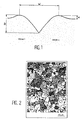
- Thermal burning is based on the fact when heating a polycrystalline solid to a temperature T in the presence of a vapor or liquid phase in thermodynamic equilibrium with the solid, grooves appear at the emergence lines of joints of grains by diffusional transport mechanisms matter (superficial diffusion, diffusion in volume and evaporation condensation). This phenomenon is described in Figure 1 which represents the furrow of the grain seal revealed thermally.
- Thermal etching of ceramics in general is carried out under an identical atmosphere to the one used in its elaboration.
- GC Grappiolo's article “Thermal etching as a high-density UO 2 ", impuls nucleare, vol 11, no. 5, May 1964 details the uranium oxide treatment. high density in a hydrogen atmosphere at 1650 ° C.
- the reductive thermal attack does not allow, like the chemical etching, to reveal in a distinct manner the areas with high plutonium contents.
- a difference in etching according to the local plutonium content of the grains is absolutely not obtained during thermal attacks of fuels (U, Pu) O 2 under reducing conditions, namely under humidified hydrogen.
- the object of the present invention is to provide a driving method intended in particular to reveal the granular structure of ceramics and in particular so-called "nuclear" ceramics such as UO 2 and (U, Pu) O 2 which do not have the disadvantages , limitations and defects of the methods of the prior art, and which solves the problems posed by the attack methods of the prior art.
- thermal attack of ceramics is known in the prior art but it is a attack under reducing atmosphere carried out at high temperature and not an attack under atmosphere oxidising at low temperature.
- the oxidative thermal attack process according to the invention in which one operates relatively low temperature, that is to say from 1250 to 1450 ° C, do not presents none of the disadvantages of the attack methods chemical.
- the temperatures implemented in the process of the invention (1250 to 1450 ° C) are significantly lower which allows to use a technology oven more simple and much less expensive. So it will be notably possible to substitute molybdenum lanthanum chromite resistors much less fragile.
- attack temperatures relatively low, below the temperature of sintering also makes it possible to limit the phenomena of granular growth, and others likely to bias the measurements made on ceramics attacked.
- the surface of the ceramic is attacked, uniformly, homogeneously, otherwise says all the grain boundaries are attacked and revealed, and the geometry of the grain boundary furrows is symmetrical, homogeneous and regular, as opposed to methods of the prior art or many grooves of grain boundaries have obvious asymmetry.
- the duration of the thermal attack according to the invention which is preferably from 15 to 30 minutes is greatly reduced which causes a important time saving.
- the device in which is realized the thermal attack according to the invention is an oven, but term covers any device, enclosure etc ... in which can be achieved the attack under the conditions of the process of the invention.
- It can be for example any oven of adequate thermal attack which usually presents a low thermal inertia allowing speeds of rise and possibly lowering temperature high.
- furnaces suitable for method of the invention there may be mentioned for example a vertical tubular furnace or thermobalance furnace.
- the oven is a controlled atmosphere oven, this usually means that the composition of the atmosphere in the interior volume of the oven is perfectly controlled, for example by performing a continuous scanning of the oven interior by the gas oxidant at a fixed, controlled rate.
- Any ceramic can be treated by the method according to the invention whether it is a so-called “technical” ceramics or so-called ceramics " nuclear ".
- the treated ceramic is preferably composed of one or more refractory oxide (s) of metals chosen, for example, from aluminum oxides, cerium oxides, metal oxides of the actinide family such as PuO 2 , UO 2 and ThO 2 and the mixed oxides of these metals such as (U, Pu) O 2 .
- s refractory oxide
- Ceramic can be a ceramic single-phase but it can also be a ceramic polyphase for example two-phase.
- the process according to the invention is particularly applicable advantageous to these polyphase ceramics which it allows to reveal the different areas, which was up to present impossible.
- said ceramic is a nuclear fuel which is preferably in the form of a pellet, prepared from UO 2 powder, or a nuclear fuel type MOX.
- MOX is a nuclear fuel (a nuclear ceramic) most often prepared by pelletizing and sintering a mixture of uranium oxide powders and plutonium oxide according to a process called MIMAS process (MIcronization of MASterblend).
- This manufacturing process generates a microstructure specific to the MOX nuclear fuel in which mother mixing zones (plutonium islands with high PuO 2 content) remain present in the matrix (zone with a low PuO 2 content and consisting essentially of UO 2 ) after sintering and are at the origin of a singular distribution of the plutonium and the size of the grains within the pellet.
- the process according to the invention carried out on MOX has the added benefit of achieving a selective attack that reveals in a way distinct matrix and plutoniferous islands or areas of mother mix.
- This difference in engraving, obtained surprisingly by the method according to the invention is never obtained by thermal attacks in reducing conditions and is due to the chemical potential of specific oxygen used in the process of the invention from -75 to -125 kJ / mol preferably from -100 kJ / mol.
- conditions of attack less oxidizing agents with a chemical potential of oxygen in outside the quoted beach and are located for example in the range of -150 kJ / mol to -200 kJ / mol does not allow not distinguish high-grade plutonium islands in plutonium from the rest of the matrix.
- the oxidizing gas is preferably constituted a carrier gas and oxygen.
- the carrier gas is preferably selected from CO 2 , argon, other inert gases such as nitrogen and mixtures thereof.
- the carrier gas is CO 2 , it has indeed been noted that CO 2 makes it possible to obtain ceramographic revelations of better quality, since this gas decomposes "in situ" at the temperatures of the heat treatment, thus providing a contribution additional oxygen in relation to the amount indicated below (that is to say, the proportion of oxygen is then, after decomposition, 100 to 3000 vpm instead of 10 to 3000 vpm as below).
- the proportion of oxygen in the oxidizing gas is in fact usually 10 to 3000 vpm, preferably 100 to 1000 vpm for example 1000 vpm.
- a preferred oxidizing gas (initially) consists of CO 2 and 10 vpm of oxygen, another oxidizing gas consists of argon and 1000 vpm of oxygen, it is thus in the range of oxygen potential. according to the invention.
- the temperature of attack that is, the temperature of the bearing is 1250 to 1450 ° C, preferably this temperature is 1300 to 1400 ° C, a temperature close to 1350 ° C appears to be an excellent compromise with regard to the quality of the revelation and the image obtained.
- attack conditions will for example be 1350 ° C. for 30 minutes under CO 2 atmosphere + 10 vpm O 2 for UO 2 and MOX ceramics.
- the temperature drop of the oven following the bearing is usually performed at the same speed as the climb, that is to say at a speed of 900 ° C / h to 1500 ° C / h to the final temperature.
- the initial and final temperatures are usually both the room temperature.
- the process is generally carried out under atmospheric pressure (1 atm).
- polishing treatment for example to using abrasive papers whose grain size is successively smaller and smaller, up to 15 ⁇ m for example. Polishing is generally done using, for example, a felt covered with diamond paste whose grains measure 1 ⁇ m.
- said operation can be any analysis and / or measurement and / or known to those skilled in the art, but preferably comprises an observation of the surface of ceramic by optical or electronic means and the measurement of grain size.
- the measurement of the size of grains is achieved by implementing software image analysis associated with said optical means such as an optical microscope.
- the invention finally relates to a ceramic polished, thermally etched, in which the surface said ceramic is etched uniformly and the geometry of the grooves of revealed grain boundaries is symmetrical, homogeneous and regular
- the uranium oxide pellets studied come from 3 batches of samples (A, B, C) made, either from uranium dioxide powders by nature different (dry or wet lot 1 and lot 2), sintered under different conditions.
- MOX fuel pellets are derived from two batches (MOX 1 and MOX 2) manufactured under similar conditions according to the MIMAS process (MIcronization of MASterblend) with both types of UO 2 powders wet lot 1 and batch 2.
- the PuO 2 powder used comes from the La Hague reprocessing plant and is in the form of lamellar platelets with a square base.
- the MIMAS process is known to man profession and will not be described further.
- Sample preparation, cutting and polishing constitutes a step essential for the microstructural study of materials by image analysis. It must be particularly neat and adapted to the materials studied.
- a series of pre-grinding on various abrasive papers respective grains of 76, 35, 22 and 15 ⁇ m, is performed, followed by final polishing on felt covered with a diamond paste whose grains measure about 1 ⁇ m.
- a cleaning of the surface is achieved between each step of (pre) polishing by immersion of the sample in an aqueous bath subjected to ultrasound.
- the stripping is done by a light heating of the resin, which by expanding release the sample.
- thermal attack furnace lies mainly in its low thermal inertia, which allows high rise (and fall) speeds in temperature.
- Two types of furnaces are used in the examples below according to the atmosphere considered and / or the oxide in question (UO 2 or (U, Pu) O 2 ).
- a vertical tube furnace PYROX VT 30® is used for the thermal attack, under oxidizing conditions, of UO 2 . That is to say in the context of the process according to the invention.
- This oven is heated by four resistors in lanthanum chromite.
- the working tube placed in the center of the four resistors, is in Al 2 O 3 dense and waterproof.
- the cooling of the flanges is ensured by circulation of water.
- an oxygen gauge zirconia probe connected at the furnace outlet , measure the oxygen partial pressure of the atmosphere.
- the maximum speeds of climb and temperature reduction are 1200 ° C / h.
- a precise implementation of the sample both in the isothermal zone of the oven and 1.5 cm from the measuring thermocouple, can guarantee a sample temperature accuracy of ⁇ 5 ° C.
- the gas supply is controlled in flow rate and pressure (flow rate 10 l / h).
- the enclosure of the oven is at atmospheric pressure in use normal.
- the oven enclosure is under pressure atmospheric.
- the etching was carried out using an acid solution (H 2 O, H 2 O 2 , H 2 SO 4 ).
- the thermal attack is carried out under a reducing atmosphere (H 2 sec) of the samples of the lots of UO 2 , A, B, and C.
- the thermal attack is carried out under oxidizing atmosphere of a sample of the batch A of UO 2 .
- the oxidizing atmosphere consists of argon and 10 vpm O 2 .
- the chemical oxygen potential of this gaseous mixture varies from -150 kJ / mol to -200 kJ / mol between 1300 ° C and 1700 ° C and therefore lies outside the values defined in the process of the invention which also operates at generally higher temperatures bass.
- the thermal attack is carried out under oxidizing atmosphere of the samples of UO 2 A, B and C batches.
- the oxidizing atmosphere consists of CO 2 and 10 vpm of O 2 .
- the only invariant parameter is the duration of the thermal attack, set at 30 minutes.
- the particle size densities of the diameter equivalent to the grain sections are compared between a chemical attack under the conditions mentioned above, and the thermal attacks according to the invention in an oxidizing atmosphere under CO 2 + 10 vpm O 2 (see Example 4). above).
- the average diameter is also determined determined by field-by-field analysis. Quartiles are also calculated. They allow to characterize the dispersion of the particle size distributions of the different attacks.
- a sampling plan was applied involving the analysis of a minimum of 1800 sections of grains according to a stratified random implantation of measurement fields.
- Lot A It appears that the material can be attacked up to a temperature of 1350 ° C without significant evolution of the microstructure.
- a temperature of 1350 ° C therefore appears as the best compromise to obtain a quality of the image sufficient, therefore able to be treated automatically without leading to a measurable evolution of the microstructure.
- Lot B The particle size distribution curves in FIG. 5 show very clearly that the thermal attack under oxidizing CO 2 atmosphere does not cause changes in the distribution and the average size of the grains.
- Attacks at 1350 ° C and 1450 ° C give a excellent result and especially allow to treat automatically images.
- Lot C we observe in figure 6 a excellent superposition of density curves granulometric allowing us to say that thermal attack does not change the structure of the batch C.
- the network of grain boundaries is revealed from excellent way for example at 1450 ° C and allows a automatic image analysis.
- the chemical attack was carried out in using 2 acid solutions.
- the thermal attack is carried out under an Argon reducing atmosphere with 5% hydrogen and 2600 vpm H 2 O samples from lots MOX 1 and MOX 2 at temperatures close to 1600 ° C and with a duration from 10 to 30 minutes.
- the thermal attack is carried out under atmosphere oxidizing samples from MOX 1 and MOX 2 batches.
- the oxidizing atmosphere consists of CO 2 and 10 vpm O 2 , the attack temperature is set at 1350 ° C and the duration of the attack is 30 minutes.
- FIGS. 7 and 8 are optical images of these 2 samples MOX 1 and MOX 2 attacked under CO 2 at 1350 ° C. for 30 minutes, they show that the whole of their structure is perfectly well revealed.
- the thermal etching of joints grain is not uniform: the grain boundaries of some isolated areas appear white while the rest of the grain boundaries is characterized by a black line, configuration usually encountered for grain boundaries of uranium dioxide.
- Figures 8 and 10 show optical micrographs of MOX 1 obtained after attack thermal: they are to be compared with FIGS. 11 which represent the X images of the plutonium of these same areas obtained on the microprobe.
- Example 8 for revealing the microstructure of MOX, by making comparisons between granulometric measurements obtained by individual analysis of the grain sections after etching and thermal attack.
- the particle size density curves of the grain sections obtained after etching and heat are comparable.
- the oxidative thermal attack under CO 2 does not modify the microstructure of the MOX fuels and allows the homogeneous revelation of the grain boundaries.
- observations are made using a scanning microscope (field effect microscope PHILIPS FEG XL 30) one of samples of UO 2 (batch A) thermally etched under an oxidizing atmosphere of argon + 10 vpm O 2 at 1650 ° C. for 30 min, under a reducing atmosphere of hydrogen at 1650 ° C. for 15 min and under an oxidizing atmosphere of CO 2 + 10 vpm of O 2 at 1350 ° C. 30 min.
- a scanning microscope field effect microscope PHILIPS FEG XL 30
- an atomic force microscope (AFM Nanoscope 2®) is used to precisely quantify the groove geometry at the grain boundaries for each of the oxidative etchings performed on the UO 2 .
- FIG. 17 shows two typical profiles of grain boundaries thermally revealed under Ar (profile a) and under CO 2 (profile b) confirming the previous qualitative observations: the grain boundaries of the sample attacked under CO 2 are symmetrical and of geometries regular. The profiles measured by AFM on these grain boundaries do not show a significant variation in depth (P) in width (L) and in height (H), unlike those measured on the sample attacked under Ar as the values show. of Table IV. Characteristic quantities of grooves at grain boundaries measured by atomic force microscopy.
- the quality of the optical image of the granular structure of the sample is so strongly conditioned by the geometry of the groove creates during thermal etching of the grain boundary.
- the image optical microstructure will appear as no even if all the grain boundaries are attacked.
Landscapes
- Physics & Mathematics (AREA)
- Engineering & Computer Science (AREA)
- Analytical Chemistry (AREA)
- Biochemistry (AREA)
- High Energy & Nuclear Physics (AREA)
- Health & Medical Sciences (AREA)
- Life Sciences & Earth Sciences (AREA)
- Chemical & Material Sciences (AREA)
- Plasma & Fusion (AREA)
- General Engineering & Computer Science (AREA)
- General Health & Medical Sciences (AREA)
- General Physics & Mathematics (AREA)
- Immunology (AREA)
- Pathology (AREA)
- Sampling And Sample Adjustment (AREA)
- Monitoring And Testing Of Nuclear Reactors (AREA)
- Inorganic Compounds Of Heavy Metals (AREA)
Description
- une attaque de la surface des grains à des vitesses différentes suivant leur orientation cristallographique. Ce facettage des grains va induire des différences de réflectivité, qui vont permettre de les individualiser lors de leur observation par microscopie optique,
- une attaque locale spécifique aux joints de grains, due au désordre cristallographique important et à la présence d'impuretés. Cette attaque va créer un sillon à l'emplacement du joint de grains dont la forme dépend des tensions superficielles et intergranulaires. Elle est donc directement liée aux différences d'orientation cristallographique des deux grains adjacents et sera donc hétérogène dans le plan de l'échantillon.
- une première attaque, destinée à révéler les zones faiblement enrichies en Pu (matrice), est réalisée par une solution acide (H2O, H2O2, H2SO4) à température ambiante pendant 2 à 20 minutes,
- l'échantillon est ensuite repoli avant de subir une seconde attaque acide (H2O, H2SO4, NH4HF2) à 70°C pendant 1 à 3 minutes. Celle-ci permet de révéler la totalité de la surface comprenant les zones à fortes et faibles teneurs en plutonium.
- impossibilité de révéler uniformément une coupe céramographique pour des raisons évoquées précédemment,
- difficulté à définir une procédure reproductible de révélation car il faut partir de solutions toujours neuves,
- coloration différente des grains, générée par les multiples orientations cristallographiques des grains, ne permettant pas l'automatisation des mesures de taille de grains,
- génération d'effluents actifs (dans le cas des céramiques « nucléaires ») et corrosion des équipements voisins par dégagements de vapeurs acides en boíte à gants.
- les expériences d'attaque thermique tirées de la littérature sont en général effectuées sur des pastilles d'UO2 préalablement recuites pendant des temps suffisamment importants, par exemple, deux semaines à 1700°C, comparativement aux durées des gravages thermiques. Ce recuit est indispensable pour stabiliser la microstructure et s'affranchir ainsi d'un éventuel grossissement des grains, qui pourrait entraíner d'autres mécanismes que celui (ou ceux) responsable(s) du gravage thermique du sillon,
- les études menées sur l'UO2+x sur-stoechiométrique ont été réalisées avec un oxyde d'uranium dont le rapport oxygène/uranium était déterminé et n'évoluait pas en cours d'expérience.
- une image optique résultante des joints de grains non uniforme. Le réseau de joints de grains binarisé automatiquement présente donc des discontinuités qui nécessitent une correction manuelle importante lors de l'étape de traitement de l'image;
- la mise en évidence de défauts cristallins tels que des stries à la surface du matériau ou des remontées de dislocations. Ces défauts génèrent un bruit de fond qui sera d'autant plus gênant que l'échantillon sera poreux, car des confusions peuvent se produire entre la porosité, le bruit de fond et le réseau de joints de grains,
- la nécessité d'une technologie de four adaptée au choc thermique et à une montée rapide à des températures voisines de 1700 °C.
- le fait d'opérer à des températures aussi élevées, qui peuvent être supérieures à la température de frittage est susceptible de favoriser des phénomènes de croissance granulaire pouvant biaiser la mesure de la taille des grains.
- montée rapide en température du four à une vitesse de 900°C/h à 1500°C/h depuis la température initiale jusqu'à un palier de température;
- maintien de la température audit palier à une valeur de 1250°C à 1450°C pendant une durée de 15 minutes à 30 minutes;
- descente en température jusqu'à la température finale.
- la structure granulaire de ladite céramique est révélée par le procédé d'attaque thermique selon l'invention tel qu'il est décrit plus haut;
- la structure ainsi révélée est soumise à une ou des opération(s) d'analyse et/ou de mesure et/ou d'observation.
- La figure 1 est une vue en coupe latérale qui représente un sillon au joint de grains révélé thermiquement.
- La figure 2 est une image optique d'un échantillon du lot A de UO2 révélé par voie chimique.
- La figure 3 est une image optique d'un échantillon du lot A de UO2 après attaque thermique 15 minutes à 1650°C sous H2 sec.
- La figure 4 est un graphique donnant les courbes de densités granulométriques d'un échantillon du lot A de UO2 obtenues après une attaque chimique (courbe en trait mixte) et des attaques thermiques sous atmosphère de CO2 + 10 vpm O2 à 1250°C, 1350°C, et 1450°C (respectivement courbes en grands pointillés, en trait plein, et en petits pointillés).
- La figure 5 est un graphique analogue à celui de la figure 4 donnant les courbes de densités granulométriques du lot B de UO2 obtenues après une attaque chimique (courbe en trait mixte), et des attaques thermiques sous atmosphère de CO2 + 10 vpm de O2 à 1350°C et 1450°C (respectivement courbes en trait plein, et en petits pointillés).
- la figure 6 est un graphique analogue à ceux des figures 4 et 5 qui donne les courbes de densités granulométriques du lot C de UO2 après attaque chimique, et attaque thermique sous atmosphère de CO2 + 10 vpm de O2 à 1450°C.
- la figure 7 est une image optique (micrographie) d'un échantillon du lot MOX 2 après attaque thermique sous CO2 + 10 vpm de O2 à 1350°C pendant 30 minutes.
- La figure 8 est une image optique d'un échantillon du lot MOX 1 après attaque thermique sous CO2 + 10 vpm de O2 à 1350°C pendant 30 minutes.
- La figure 9 est une image X correspondant à l'image optique de la figure 8.
- La figure 10 est une image optique d'un échantillon du lot MOX 1 après attaque thermique sous CO2 et 10 vpm de CO2 à 1350°C pendant 30 minutes.
- La figure 11 est une image X correspondant à l'image optique de la figure 10.
- La figure 12 est un graphique analogue à ceux des figures 2 à 4 qui donne les courbes de densités granulométriques d'un échantillon du lot MOX 1 après attaques chimique et thermique sous CO2 + 10 vpm de O2 à 1350°C pendant 30 minutes.
- La figure 13 est un graphique analogue à celui de la figure 12 mais relatif à un échantillon du lot MOX 2.
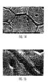
- La figure 14 est une image électronique (micrographie) d'un échantillon du lot A (UO2) attaqué sous Ar + 10 vpm O2 à 1650°C qui met en évidence un joint de grains dissymétrique.
- La figure 15 est un « zoom » de la micrographie de la figure 15.
- La figure 16 est une image électronique d'un échantillon du lot A attaqué sous CO2 + 10 vpm O2 à 1350 °C qui montre l'uniformité de la révélation.
- la figure 17 est un schéma qui présente les profils de joints de grains mesurés par microscope à force atomique (AFM) sur de l'UO2 attaqué thermiquement sous Ar + 10 vpm de O2 (profil a) et sous CO2 + 10 vpm de O2 (profil b).
- vitesses de montée et de descente en température de 1200°C/h,
- précision sur la mesure de la température de ± 5°C,
- débit de gaz (H2 ou CO2) de 10 l/h.
| Conditions opératoires des expériences réalisées sous H2 sec | |
| TEMPERATURE (°C) | DUREE D'ATTAQUE (min) |
| 1550 | 30 |
| 1550 | 60 |
| 1600 | 15 |
| 1600 | 30 |
| 1650 | 15 |
| 1650 | 30 |
- une image optique résultante non uniforme (voir figure 3).
- la mise en évidence de défauts cristallins tels que des stries à la surface du matériau ou des remontées de dislocations. Ces défauts génèrent un bruit de fond qui sera d'autant plus gênant que l'échantillon sera poreux, car des confusions peuvent se produire entre la porosité, le bruit de fond et le réseau de joints de grains,
- la nécessité d'une technologie de four adaptée au choc thermique et à une montée rapide à des températures voisines de 1700 °C.
| Conditions opératoires de l'attaque thermique sous Ar + 10 vpm O2 | |
| Température (°C) | Durée d'attaque (min) |
| 1300 | 60 |
| 1550 | 30 |
| 1600 | 30 |
| 1650 | 10 |
| 1650 | 30 |
| 1680 | 5 |

- sous argon ou H2, certains sillons de joints de grains présentent une dissymétrie évidente dans leur géométrie (figures 14 et 15). On notera bien cependant, que tous les joints de grains sont attaqués et révélés contrairement à ce que l'on peut observer au microscope optique du fait de l'ouverture numérique des optiques utilisées.
- sous CO2, on montre que la surface est attaquée uniformément et que la géométrie des sillons apparaít symétrique et homogène (figure 16).
| Grandeurs caractéristiques des sillons aux joints de grains mesurées par microscopie à force atomique. | |||
| Nature du gaz d'attaque utilisé | Hauteurs minimale et maximale mesurées (nm) | Largeurs minimale et maximale mesurées(µm) | Profondeurs minimale et maximale mesurées(nm) |
| Argon + 10 vpm O2 | 2-10 | 0,2-1 | 7-18 |
| CO2 + 10 vpm O2 | 1-3 | 0,5-0,9 | 13-19 |
Claims (20)
- Procédé d'attaque thermique d'une céramique dans lequel ladite attaque thermique est réalisée dans un four à atmosphère contrôlée constituée par un gaz oxydant fournissant un potentiel chimique d'oxygène de -75 kJ/mol à -125 kJ/mol, et comprend les étapes successives suivantes:montée rapide en température du four à une vitesse de 900°C/h à 1500°C/h depuis la température initiale jusqu'à un palier en température;maintien de la température audit palier à une valeur de 1250°C à 1450°C pendant une durée de 30 minutes à 15 minutes;descente en température jusqu'à la température finale.
- Procédé selon la revendication 1 dans lequel ladite céramique est constituée par un ou plusieurs oxyde(s) réfractaire(s) de métaux choisis parmi les oxydes de d'aluminium, les oxydes de cérium, les oxydes de métaux de la famille des actinides tels que U, Pu et Th, et les oxydes mixtes de ces métaux.
- Procédé selon la revendication 2 dans lequel ladite céramique est une céramique monophasée.
- Procédé selon la revendication 2 dans lequel ladite céramique est une céramique polyphasée
- Procédé selon la revendication 3 dans lequel ladite céramique est un combustible nucléaire préparé à partir de poudre d'UO2.
- Procédé selon la revendication 4 dans lequel ladite céramique est un combustible nucléaire du type (U, Pu)O2.
- Procédé selon la revendication 1 dans lequel ledit gaz oxydant est constitué d'un gaz vecteur et d'oxygène.
- Procédé selon la revendication 7 dans lequel le gaz vecteur est choisi parmi le CO2, l'argon, les autres gaz inertes et leurs mélanges.
- Procédé selon l'une quelconque des revendications 7 et 8 dans lequel le gaz oxydant contient de 10 à 3000 vpm d'oxygène.
- Procédé selon la revendication 9 dans lequel le gaz oxydant est constitué de CO2 et de 10 vpm d'oxygène.
- Procédé selon la revendication 9 dans lequel le gaz oxydant est constitué d'argon et de 1000 vpm d'oxygène.
- Procédé selon la revendication 1 dans lequel la température du palier est de 1300°C à 1400°C.
- Procédé selon la revendication 12 dans lequel la température du palier est de 1350°C.
- Procédé selon la revendication 1 dans lequel le potentiel d'oxygène fourni par le gaz oxydant est d'environ -100 kJ/mol.
- Procédé selon la revendication 1 dans lequel la descente en température du four est réalisée à une vitesse de 900°C/h à 1500°C/h.
- Procédé selon la revendication 1 dans lequel la céramique est préalablement soumise à un traitement de polissage.
- Procédé d'étude de la microstructure d'une céramique dans lequella structure granulaire de ladite céramique est révélée par le procédé d'attaque thermique selon l'une quelconque des revendications 1 à 16la structure ainsi révélée, est soumise à une ou des opération(s) d'analyse et/ou de mesure et/ou d'observation.
- Procédé selon la revendication 17 dans lequel ladite opération d'analyse et/ou de mesure et/ou d'observation comprend une observation de la surface de la céramique par des moyens optique ou électroniques et la mesure de la taille des grains.
- Procédé selon la revendication 18 dans lequel la mesure de la taille des grains est réalisée en mettant en oeuvre un logiciel d'analyse des images obtenues associés auxdits moyens optiques.
- Céramique polie, attaquée thermiquement par le procédé selon l'une quelconque des revendications 1 à 16, dans laquelle la surface de ladite céramique est attaquée uniformément et la géométrie des sillons de joints de grains révélés est symétrique, homogène et régulière.
Applications Claiming Priority (2)
| Application Number | Priority Date | Filing Date | Title |
|---|---|---|---|
| FR9713168A FR2769983B1 (fr) | 1997-10-21 | 1997-10-21 | Procede d'attaque thermique en conditions oxydantes d'une ceramique |
| FR9713168 | 1997-10-21 |
Publications (2)
| Publication Number | Publication Date |
|---|---|
| EP0911624A1 EP0911624A1 (fr) | 1999-04-28 |
| EP0911624B1 true EP0911624B1 (fr) | 2003-07-16 |
Family
ID=9512462
Family Applications (1)
| Application Number | Title | Priority Date | Filing Date |
|---|---|---|---|
| EP98402583A Expired - Lifetime EP0911624B1 (fr) | 1997-10-21 | 1998-10-19 | Procédé d'attaque thermique en conditions oxydantes d'une ceramique |
Country Status (7)
| Country | Link |
|---|---|
| US (1) | US6171511B1 (fr) |
| EP (1) | EP0911624B1 (fr) |
| JP (1) | JP4443655B2 (fr) |
| KR (1) | KR100553700B1 (fr) |
| DE (1) | DE69816397T2 (fr) |
| FR (1) | FR2769983B1 (fr) |
| RU (1) | RU2208003C2 (fr) |
Families Citing this family (11)
| Publication number | Priority date | Publication date | Assignee | Title |
|---|---|---|---|---|
| JP3692075B2 (ja) * | 1999-06-15 | 2005-09-07 | ハンヤン ハク ウォン カンパニー,リミテッド | Cf4/o2/n2プラズマ中におけるアクチニド酸化物およびその混合酸化物の効果的なドライエッチング法 |
| KR100712715B1 (ko) | 2001-01-31 | 2007-05-04 | 도시바세라믹스가부시키가이샤 | 표면에 미세한 돌기를 형성시킨 세라믹스부재 및 그제조방법 |
| RU2243533C1 (ru) * | 2003-07-02 | 2004-12-27 | Томский политехнический университет | Способ выявления микроструктуры керамических материалов |
| CN101230877A (zh) * | 2007-01-24 | 2008-07-30 | 富准精密工业(深圳)有限公司 | 转动体及其制造方法 |
| CN106092708B (zh) * | 2016-06-06 | 2020-02-04 | 四川建筑职业技术学院 | 一种300m钢晶粒度的腐蚀显现方法 |
| RU2679117C1 (ru) * | 2018-02-01 | 2019-02-06 | Федеральное государственное бюджетное учреждение науки Институт химии Дальневосточного отделения Российской академии наук (ИХ ДВО РАН) | Способ получения керамического ядерного топлива |
| US12288320B2 (en) | 2020-12-22 | 2025-04-29 | University Of South Carolina | Experimental set up for studying temperature gradient driven cracking |
| CN113176181A (zh) * | 2021-04-28 | 2021-07-27 | 钢铁研究总院 | 一种晶粒尺寸测试方法 |
| CN113960085A (zh) * | 2021-09-22 | 2022-01-21 | 中国工程物理研究院激光聚变研究中心 | 一种有色金属多晶材料晶粒尺寸的高效测量方法 |
| CN115351304B (zh) * | 2022-08-19 | 2025-07-11 | 宁波江丰电子材料股份有限公司 | 一种用于铜材晶粒观测的表面处理方法 |
| CN119124783A (zh) * | 2024-09-27 | 2024-12-13 | 宁波江丰电子材料股份有限公司 | 一种氧化锆陶瓷待测样品及其制备方法和应用 |
Family Cites Families (10)
| Publication number | Priority date | Publication date | Assignee | Title |
|---|---|---|---|---|
| US3859403A (en) * | 1970-04-13 | 1975-01-07 | Sprague Electric Co | Process for semiconductive ceramic body |
| JPS5742237B2 (fr) * | 1975-01-11 | 1982-09-07 | ||
| DE3443817A1 (de) * | 1983-12-02 | 1985-06-27 | Director General of Agency of Industrial Science and Technology Itaru Todoriki, Tokio/Tokyo | Verfahren zur herstellung von keramik |
| US4548903A (en) * | 1984-03-30 | 1985-10-22 | The United States Of America As Represented By The Secretary Of The Air Force | Method to reveal microstructures in single phase alloys |
| SU1235856A1 (ru) * | 1985-01-07 | 1986-06-07 | Предприятие П/Я Р-6681 | Способ вы влени микроструктуры керамического материала |
| JPS63303867A (ja) * | 1987-01-12 | 1988-12-12 | Ngk Insulators Ltd | 窒化珪素セラミックス部品の製造法 |
| JPH0688895A (ja) * | 1992-09-08 | 1994-03-29 | Mitsubishi Nuclear Fuel Co Ltd | 核燃料ペレットの結晶粒径推定方法 |
| JPH0715432B2 (ja) * | 1992-09-18 | 1995-02-22 | 科学技術庁無機材質研究所長 | 燃焼炎を用いたセラミックスの簡易エッチング法 |
| JP2616372B2 (ja) * | 1993-01-06 | 1997-06-04 | 住友金属工業株式会社 | 半導体磁器素子の製造方法 |
| JPH0784274A (ja) * | 1993-09-16 | 1995-03-31 | A G Technol Kk | 優先配向を有するito薄膜作成方法 |
-
1997
- 1997-10-21 FR FR9713168A patent/FR2769983B1/fr not_active Expired - Fee Related
-
1998
- 1998-10-19 EP EP98402583A patent/EP0911624B1/fr not_active Expired - Lifetime
- 1998-10-19 DE DE69816397T patent/DE69816397T2/de not_active Expired - Lifetime
- 1998-10-20 RU RU98119061/03A patent/RU2208003C2/ru not_active IP Right Cessation
- 1998-10-21 KR KR1019980044186A patent/KR100553700B1/ko not_active Expired - Fee Related
- 1998-10-21 JP JP31839098A patent/JP4443655B2/ja not_active Expired - Fee Related
- 1998-10-21 US US09/176,604 patent/US6171511B1/en not_active Expired - Fee Related
Also Published As
| Publication number | Publication date |
|---|---|
| FR2769983B1 (fr) | 1999-12-03 |
| JPH11231085A (ja) | 1999-08-27 |
| KR100553700B1 (ko) | 2006-08-03 |
| KR19990037274A (ko) | 1999-05-25 |
| FR2769983A1 (fr) | 1999-04-23 |
| RU2208003C2 (ru) | 2003-07-10 |
| JP4443655B2 (ja) | 2010-03-31 |
| DE69816397T2 (de) | 2004-04-22 |
| US6171511B1 (en) | 2001-01-09 |
| EP0911624A1 (fr) | 1999-04-28 |
| DE69816397D1 (de) | 2003-08-21 |
Similar Documents
| Publication | Publication Date | Title |
|---|---|---|
| TW486749B (en) | Semiconductor silicon wafer, semiconductor silicon wafer fabrication method and annealing equipment | |
| EP0911624A1 (fr) | Procédé d'attaque thermique en conditions oxydantes d'une ceramique | |
| EP2474000B1 (fr) | Procede de preparation d'un combustible nucleaire poreux a base d'au moins un actinide mineur | |
| CA2822764C (fr) | Procede de preparation d'une poudre d'un alliage a base d'uranium et de molybdene | |
| Guerain et al. | The use of micro-Raman imaging to measure 18O tracer distribution in thermally grown zirconia scales | |
| EP2125660B1 (fr) | Materiau ceramique refractaire a haute temperature de solidus, son procede de fabrication et piece de structure incorporant ledit materiau | |
| FR2969661A1 (fr) | Poudre d'un alliage a base d'uranium et de molybdene utile pour la fabrication de combustibles nucleaires | |
| Ivanits’ ka et al. | Chemical etching of CdTe in aqueous solutions of H2O2-HI-citric acid | |
| Moriya | Observation of micro-defects in as-grown and heat treated Si crystals by infrared laser scattering tomography | |
| Black et al. | Precipitates Induced in GaAs by the In‐Diffusion of Zinc | |
| Yurek et al. | Microstructures of the scales formed on zircaloy-4 in steam at elevated temperatures | |
| EP0892862B1 (fr) | Electrolyte pour l'electropolissage, procede d'electropolissage d'un acier inoxydable ou d'un alliage de nickel mettant en oeuvre cet electrolyte, et son application a la decontamination | |
| Yamamuro et al. | Effect of dopant concentration on femtosecond pulsed laser irradiation of yttria-stabilized zirconia for generating nanopores | |
| Kurt et al. | Effect of trace elements lead and tin on anodic activation of AA8006 aluminum sheet | |
| Allongue et al. | Structure sensitive in situ Raman study of iron passive films using SERS-active Fe∕ Au (111) substrates | |
| Yukimoto | The Origin and Structures of the Anomalous Defects Observed in Silicon Crystals | |
| Pearce et al. | Oxidation kinetics of single crystal titanium nitride by optical measurements | |
| Tabor | Solid surfaces: their atomic, electronic and macroscopic properties | |
| EP3380787B1 (fr) | Générateur de vapeur, procédés de fabrication et utilisations correspondantes | |
| Huang et al. | REM in a UHV TEM for the observation of dynamic phase transformation processes on the Cu3Au (111) surface | |
| Pickering et al. | Atom probe analysis of segregation in Fe–0.15 wt.% Ti | |
| McKerracher et al. | Selective intermixing of InGaAs/GaAs quantum dot infrared photodetectors | |
| Alvani et al. | Optical reflectivity measurements on thorium metal samples | |
| WO2025181035A1 (fr) | Procédé de traitement de surface de métaux ou céramiques avec un faisceau laser à onde continue et système associé | |
| Gotta et al. | Experimental microstructures MOX fuels elaboration |
Legal Events
| Date | Code | Title | Description |
|---|---|---|---|
| PUAI | Public reference made under article 153(3) epc to a published international application that has entered the european phase |
Free format text: ORIGINAL CODE: 0009012 |
|
| AK | Designated contracting states |
Kind code of ref document: A1 Designated state(s): BE CH DE GB LI NL SE |
|
| AX | Request for extension of the european patent |
Free format text: AL;LT;LV;MK;RO;SI |
|
| 17P | Request for examination filed |
Effective date: 19991014 |
|
| RAP1 | Party data changed (applicant data changed or rights of an application transferred) |
Owner name: COMPAGNIE GENERALE DES MATIERES NUCLEAIRES Owner name: COMMISSARIAT A L'ENERGIE ATOMIQUE |
|
| AKX | Designation fees paid |
Free format text: BE CH DE GB LI NL SE |
|
| GRAH | Despatch of communication of intention to grant a patent |
Free format text: ORIGINAL CODE: EPIDOS IGRA |
|
| GRAH | Despatch of communication of intention to grant a patent |
Free format text: ORIGINAL CODE: EPIDOS IGRA |
|
| GRAA | (expected) grant |
Free format text: ORIGINAL CODE: 0009210 |
|
| AK | Designated contracting states |
Designated state(s): BE CH DE GB LI NL SE |
|
| REG | Reference to a national code |
Ref country code: GB Ref legal event code: FG4D Free format text: NOT ENGLISH |
|
| REG | Reference to a national code |
Ref country code: CH Ref legal event code: EP |
|
| REF | Corresponds to: |
Ref document number: 69816397 Country of ref document: DE Date of ref document: 20030821 Kind code of ref document: P |
|
| PG25 | Lapsed in a contracting state [announced via postgrant information from national office to epo] |
Ref country code: LI Free format text: LAPSE BECAUSE OF NON-PAYMENT OF DUE FEES Effective date: 20031031 Ref country code: CH Free format text: LAPSE BECAUSE OF NON-PAYMENT OF DUE FEES Effective date: 20031031 |
|
| REG | Reference to a national code |
Ref country code: SE Ref legal event code: TRGR |
|
| GBT | Gb: translation of ep patent filed (gb section 77(6)(a)/1977) |
Effective date: 20031027 |
|
| PG25 | Lapsed in a contracting state [announced via postgrant information from national office to epo] |
Ref country code: NL Free format text: LAPSE BECAUSE OF NON-PAYMENT OF DUE FEES Effective date: 20040501 |
|
| PLBE | No opposition filed within time limit |
Free format text: ORIGINAL CODE: 0009261 |
|
| STAA | Information on the status of an ep patent application or granted ep patent |
Free format text: STATUS: NO OPPOSITION FILED WITHIN TIME LIMIT |
|
| REG | Reference to a national code |
Ref country code: CH Ref legal event code: PL |
|
| NLV4 | Nl: lapsed or anulled due to non-payment of the annual fee |
Effective date: 20040501 |
|
| 26N | No opposition filed |
Effective date: 20040419 |
|
| PGFP | Annual fee paid to national office [announced via postgrant information from national office to epo] |
Ref country code: DE Payment date: 20101022 Year of fee payment: 13 |
|
| PGFP | Annual fee paid to national office [announced via postgrant information from national office to epo] |
Ref country code: SE Payment date: 20101014 Year of fee payment: 13 |
|
| REG | Reference to a national code |
Ref country code: SE Ref legal event code: EUG |
|
| PG25 | Lapsed in a contracting state [announced via postgrant information from national office to epo] |
Ref country code: DE Free format text: LAPSE BECAUSE OF NON-PAYMENT OF DUE FEES Effective date: 20120501 |
|
| REG | Reference to a national code |
Ref country code: DE Ref legal event code: R119 Ref document number: 69816397 Country of ref document: DE Effective date: 20120501 |
|
| PG25 | Lapsed in a contracting state [announced via postgrant information from national office to epo] |
Ref country code: SE Free format text: LAPSE BECAUSE OF NON-PAYMENT OF DUE FEES Effective date: 20111020 |
|
| PGFP | Annual fee paid to national office [announced via postgrant information from national office to epo] |
Ref country code: GB Payment date: 20141015 Year of fee payment: 17 |
|
| PGFP | Annual fee paid to national office [announced via postgrant information from national office to epo] |
Ref country code: BE Payment date: 20141030 Year of fee payment: 17 |
|
| GBPC | Gb: european patent ceased through non-payment of renewal fee |
Effective date: 20151019 |
|
| PG25 | Lapsed in a contracting state [announced via postgrant information from national office to epo] |
Ref country code: GB Free format text: LAPSE BECAUSE OF NON-PAYMENT OF DUE FEES Effective date: 20151019 |
|
| PG25 | Lapsed in a contracting state [announced via postgrant information from national office to epo] |
Ref country code: BE Free format text: LAPSE BECAUSE OF NON-PAYMENT OF DUE FEES Effective date: 20151031 |