EP0911064B1 - Bestrahlungsvorrichtung und rotatives Bestrahlungssystem mit Hilfe von geladenen Teilchenstrahlen - Google Patents
Bestrahlungsvorrichtung und rotatives Bestrahlungssystem mit Hilfe von geladenen Teilchenstrahlen Download PDFInfo
- Publication number
- EP0911064B1 EP0911064B1 EP98116272A EP98116272A EP0911064B1 EP 0911064 B1 EP0911064 B1 EP 0911064B1 EP 98116272 A EP98116272 A EP 98116272A EP 98116272 A EP98116272 A EP 98116272A EP 0911064 B1 EP0911064 B1 EP 0911064B1
- Authority
- EP
- European Patent Office
- Prior art keywords
- charged
- particle beam
- irradiation
- scanning
- irradiated
- Prior art date
- Legal status (The legal status is an assumption and is not a legal conclusion. Google has not performed a legal analysis and makes no representation as to the accuracy of the status listed.)
- Expired - Lifetime
Links
Images


Classifications
-
- G—PHYSICS
- G21—NUCLEAR PHYSICS; NUCLEAR ENGINEERING
- G21K—HANDLING OF PARTICLES OR IONISING RADIATION NOT OTHERWISE PROVIDED FOR; IRRADIATION DEVICES; GAMMA RAY OR X-RAY MICROSCOPES
- G21K5/00—Irradiation devices
- G21K5/04—Irradiation devices with beam-forming means
-
- A—HUMAN NECESSITIES
- A61—MEDICAL OR VETERINARY SCIENCE; HYGIENE
- A61N—ELECTROTHERAPY; MAGNETOTHERAPY; RADIATION THERAPY; ULTRASOUND THERAPY
- A61N5/00—Radiation therapy
- A61N5/10—X-ray therapy; Gamma-ray therapy; Particle-irradiation therapy
-
- A—HUMAN NECESSITIES
- A61—MEDICAL OR VETERINARY SCIENCE; HYGIENE
- A61N—ELECTROTHERAPY; MAGNETOTHERAPY; RADIATION THERAPY; ULTRASOUND THERAPY
- A61N5/00—Radiation therapy
- A61N5/10—X-ray therapy; Gamma-ray therapy; Particle-irradiation therapy
- A61N5/1042—X-ray therapy; Gamma-ray therapy; Particle-irradiation therapy with spatial modulation of the radiation beam within the treatment head
- A61N5/1043—Scanning the radiation beam, e.g. spot scanning or raster scanning
-
- A—HUMAN NECESSITIES
- A61—MEDICAL OR VETERINARY SCIENCE; HYGIENE
- A61N—ELECTROTHERAPY; MAGNETOTHERAPY; RADIATION THERAPY; ULTRASOUND THERAPY
- A61N5/00—Radiation therapy
- A61N5/10—X-ray therapy; Gamma-ray therapy; Particle-irradiation therapy
- A61N2005/1085—X-ray therapy; Gamma-ray therapy; Particle-irradiation therapy characterised by the type of particles applied to the patient
- A61N2005/1087—Ions; Protons
Definitions
- the present invention relates to a charged-particle beam irradiation apparatus, a charged-particle beam rotary irradiation system, and a charged-particle beam irradiation method which are adapted to a therapeutic apparatus using a charged-particle beam or the like.
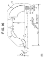
- Fig. 16 shows an example of a charged-particle beam rotary irradiation system that is a conventional therapeutic apparatus using a charged-particle beam disclosed in, for example, a report written by Pedroni of Switzerland (Medical Physics, Vol. 22, PP.37-53).
- a charged-particle beam rotary irradiation system 100 a particle accelerator 1, a transporting electromagnet 3, an energy degrader 5, a proton beam 7, a beam stopper 9, a rotating gantry 10, deflective electromagnets 11, 13, and 19, convergent electromagnets 15, a scanning electromagnet 17, an energy degrader 21, a dose/position monitor 23, a patient 25, a radiation table 27, and an axis of rotation of the gantry 29.
- a proton beam generated by the accelerator 1 is transported by the transporting electromagnet 3, passed by the energy degrader 5 serving as an initial-stage energy changing means, and thus recomposed into a proton beam 7 having given energy level.
- the proton beam 7 is deflected upward from a horizontal direction by the first deflective electromagnet 11, and then returned to the horizontal direction by the deflective electromagnet 13.
- the proton beam 7 is converged by the convergent electromagnets 15, and swept vertically by the scanning electromagnet 17.
- the swept proton beam is deflected immediately downward by the last deflective electromagnet 19, and then irradiated to the patient 25 via the energy degrader for fine adjustment 21 and the dose/position monitor 23.
- the electromagnets 11, 13, 15, 17, and 19, energy degrader 21, and monitor 23 are integrated into one unit, thus forming an irradiation gantry.
- the irradiation gantry can make a turn about the axis of rotation 29 and is referred to as the rotating gantry 10.
- the spot of the proton beam irradiated to the patient 25 is shifted parallel to an X-axis direction alone shown in Fig. 16 by means of the scanning electromagnet 17 and deflective electromagnet 19.
- Scanning the patient in a Y-axis direction which is required for a therapeutic procedure is achieved by moving the radiation table 27.
- Scanning the patient 25 in a depth direction (Z-axis direction) of the patient 25 is achieved by adjusting the energy of the proton beam using the energy degrader 21.
- the length of the rotating gantry 10 in the longitudinal direction thereof is approximately 10 m.
- a length in the gantry where the proton beam is displaced away from the gantry rotation axis 29 is approximately 2m.
- spot scanning in which the spot of a beam is shifted parallel to one axial direction alone (the X-axis direction in the above example) can solely be realized.
- the patient 25 must be moved in the Y-axis direction by moving the table 27 during treatment. This poses a problem that the movement gives the patient senses of discomfort and fear and results in displacement of a radiation area.
- the scanning electromagnet 17 since the spot of a beam parallel to an axis of incidence thereof is shifted, the scanning electromagnet 17 must be placed upstream of the deflective electromagnet 19. Accordingly the deflective electromagnet 19 for deflecting a proton beam, i.e. the charged-particle beam, which is swept vertically by the scanning electromagnet 17, becomes large in size. As a result, the total weight of the treatment rotating gantry 10 becomes 100 tons or more. Moreover, since the deflective electromagnet 19 is so large as to have magnetic poles of several tens centimeters wide, when a superconducting magnet is employed, there arises a problem of very high manufacturing cost.
- Wobbler systems using two rotating permanent dipoles are also known as scanning systems ('Instrumentation for treatment of cancer using proton and light-ion beams; Chu W.T. et al, Review of Scientific Instruments, NY, US, August 1993, vol. 64, no 8, pages 2055-2122).
- An object of the present invention is to provide a charged-particle beam irradiation apparatus, charged-particle beam rotary irradiation system, and charged-particle beam irradiation method realizing spot scanning, in which the spot of a beam parallel to an axis of incidence thereof is shifted two axial directions within a radiation area, without the necessity of moving a table, and employing a rotating gantry of a compact and lightweight design.
- a charged-particle beam irradiation apparatus comprising a scanning field generating means for generating a scanning field composed of a pair of fields effective in bending a charged-particle beam by the same angle in mutually opposite directions, and a rotating means for rotating the scanning field generating means with the axis of incidence of the charged-particle beam as a center.
- a charged-particle beam irradiation apparatus characterized in that the scanning field generating means generates magnetic fields.
- a charged-particle beam irradiation apparatus characterized in that the scanning field generating means generates electric fields.
- a charged-particle beam rotary irradiation system comprising: a deflecting means for deflecting a charged-particle beam perpendicularly to a radiation plane; a charged-particle beam irradiation apparatus that includes a scanning field generator, located downstream of the deflecting means, for generating a scanning field composed of a pair of fields effective in bending the charged-particle beam by the same angle in mutually opposite directions, and a rotator for rotating the scanning field generator with the axis of incidence of the charged-particle beam as a center, and that sweeps the charged-particle beam deflected by the deflecting means for the purpose of scan; a charged-particle beam energy adjusting means interposed between the charged-particle beam irradiation apparatus and an irradiated subject; and a rotary motion means for rotating at least the deflecting means and charged-particle beam irradiation apparatus in one united body.
- the charged-particle beam falls on the deflecting means from the direction of the axis of rotation of the rotary motion means.
- the deflecting means includes three deflective electromagnets for deflecting an incident charged-particle beam three times by 90° with respect to a direction parallel to the radiation plane so that the charged-particle beam is perpendicular to the radiation plane.
- the irradiated subject is positioned on the axis of rotation of the rotary motion means.
- a charged-particle beam rotary irradiation system characterized in that the deflective electromagnets included in the deflecting means are realized with superconducting electromagnets.
- a charged-particle beam irradiation system comprising: a charged-particle beam irradiation apparatus that includes a scanning field generator for generating a scanning field composed of a pair of fields effective in bending a charged-particle beam by the same angle in mutually opposite directions, and a rotator for rotating the scanning field generator with the axis of incidence of the charged-particle beam as a center, and that sweeps the charged-particle beam for the purpose of scan; a charged-particle beam energy adjusting means, interposed between the charged-particle beam irradiation apparatus and irradiated subject, for adjusting the energy of a charged-particle beam; a dose/position measuring means, interposed between the charged-particle beam irradiation apparatus and irradiated subject, for monitoring the dose and position of an irradiated charged-particle beam; and a control means, connected to the respective means, for controlling scan.
- the fourth means retains the angle of rotation of the scanning field generator at a certain value, modifies the intensity of a field generated by the scanning field generator and the energy of a charged-particle beam in given order, and thus actuates the first to third means repeatedly.
- a charged-particle beam irradiation system comprising: a charged-particle beam irradiation apparatus that includes a scanning field generator for generating a scanning field composed of a pair of fields effective in bending a charged-particle beam by the same angle in mutually opposite directions, and a rotator for rotating the scanning field generator with the axis of incidence of the charged-particle beam as a center, and that sweeps the charged-particle beam for the purpose of scan; a charged-particle beam energy adjusting means, interposed between the charged-particle beam irradiation apparatus and an irradiated subject, for adjusting the energy of a charged-particle beam; a dose/position measuring means, interposed between the charged-particle beam irradiation apparatus and irradiated subject, for monitoring the does and position of an irradiated charged-particle beam; a means for stopping a charged-particle beam; and a control means, connected to the respective means, for controlling scan
- a charged-particle beam irradiation system characterized in that Iij(t) ⁇ t is adopted as Iij(t) defining the scan pattern that is the characteristic curve relative to time to be followed by the scanning field generator.
- n] (i 1 that is an initial value) defining the radiation field; a second step of irradiating a charged-particle beam according to the setting; a third step of, when the number of deposited particles of a charged-particle beam becomes equal to or larger than a pre-set number of particles or when a coordinate of a position to which a charged-particle beam is irradiated is inconsistent with a coordinate of a pre-set position, stopping the charged-particle beam; and a fourth step at which when a charged-particle beam is stopped, it is judged whether or not irradiation to the whole radiation area is completed, at which if the irradiation is not completed, control is returned to the first step, i is incremented by one, the angle of rotation and field intensity concerning the scanning field generating means, and the energy of the charged-particle beam are modified in a given order, and the first to third steps are thus repeated, and at which if the irradiation is completed, irradiation is terminate
- a charged-particle beam irradiation method in which at the fourth step, the angle of rotation of the scanning field generating means is retained at a certain value, the intensity of a field generated by the scanning field generating means and the energy of a charged-particle beam are modified in given order, and the first to third steps are thus repeated.
- a charged-particle beam irradiation method in which the scanning field generating means shifts a beam spot over the radius alone of the radiation area during one beam spill, and Iij(t) ⁇ t is adopted as Iij(t) defining the scan pattern that is the characteristic curve relative to time.
- Fig. 1 is a diagram showing the structure of a charged-particle beam irradiation apparatus in accordance with an embodiment of the present invention.
- a charged-particle beam irradiation apparatus 20 an axis of incidence of a beam 30, a charged-particle beam 31 (for example, a proton beam or carbon-particle beam), and two scanning electromagnets 33 and 35 that generate homogeneous magnetic fields which are oriented in mutually opposite directions and whose intensities and effective lengths (length along the axis of incidence 30) are mutually the same, and that are placed with a certain space between them along the axis of incidence 30 of a charged-particle beam.
- Reference numeral 41 denotes the width of the magnetic poles of the scanning electromagnets 33 and 35
- 43 denotes a gap between magnetic poles.
- linkage frames 45 and 47 for linking the electromagnets 33 and 35.
- Reference numeral 55 denotes an example of the trajectory of a swept charged-particle beam.
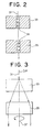
- Fig. 2 is an A-A sectional view of the charged-particle beam irradiation apparatus shown in Fig. 1.
- reference numeral 34 denotes the directions of magnetic fields generated by the scanning electromagnets 33 and 35.
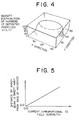
- Fig. 3 is a perspective side view of the scanning electrodes 33 and 35 seen in the direction of arrow B in Fig. 1, showing swept states of a charged-particle beam.
- the incident charged-particle beam 31 is first bent by a certain angle by the scanning electromagnet 33, and then bent in an opposite direction by the same angle by the scanning electromagnet 35 of which magnetic field is oriented in the opposite direction and has the same intensity and effective length as the magnetic field of the scanning electromagnet 33. Consequently, a beam parallel to the original charged-particle beam 31 is irradiated. As a result, the charged-particle beam swept along a scan trajectory that is the sweeping trajectory 55 is always parallel to the incident beam 31.
- the relationship between the size of a flowing current and a distance by which the beam 31 is swept away from the axis of incidence 30 is, as shown in Fig. 5, a relationship of direct proportion.
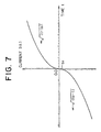
- a current I(t) flowing into the scanning electromagnets 33 and 35 is controlled as indicated in Fig. 6 or 7, the sweeping speed will be inversely proportional to the distance by which the beam 31 is swept away from the axis of incidence 30.
- the intensities and effective lengths of the magnetic fields of the scanning electromagnetic 33 and 35 are mutually the same. As long as the beam 31 is bent by the same angle in mutually opposite directions, the intensities and effective lengths of the magnetic fields may be not mutually the same.
- the two electromagnets 33 and 35 are employed. As long as a scanning field composed of a pair of fields effective in bending the charged-particle beam 31 by the same angle in mutually opposite directions can be generated, a single electromagnet or a plurality of electromagnets will do. Otherwise, a scanning field generator including a permanent magnet devised to generate a scanning field (for example, a permanent magnet whose spatial location can be varied mechanically) will do.
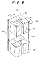
- Fig. 8 shows an example of a scanning field generating means using two C-shaped scanning electromagnets 33 and 35.
- the width 41 of the magnetic poles of the electromagnet 33 may be smaller than that of the electromagnet 35.
- the overall weight of the irradiation apparatus 20 can be reduced.
- the section of the magnetic poles of the electromagnet 33 may be shaped like a sector.
- the gap 43 between the magnetic poles of each of the scanning electromagnets 33 and 35 can be made as small as the size of the section of the incident charged-particle beam 31, because it is unnecessary to sweep the charged-particle beam in a direction traversing the gap 43.
- a compact charged-particle beam irradiation apparatus having a simple structure and capable of realizing spot scanning in which the spot of a beam parallel to the axis of incidence thereof is shifted in two axial directions can be realized.
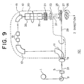
- Fig. 9 is a diagram showing the configuration of a charged-particle beam rotary irradiation system in accordance with another embodiment of the present invention which is used as a modality using a charged-particle beam.
- the charged-particle beam rotary irradiation system 101 shown in Fig. 9 has a charged-particle beam irradiation apparatus 20 in accordance with the aforesaid embodiment interposed between a deflective electromagnet 19 and an energy degrader 21.
- a beam 31 having not been swept falls on the deflective electromagnet 19.
- the deflective electromagnet 19 is therefore much smaller than a conventional one. Consequently, a patient 25 that is an irradiated subject can be positioned on the axis of rotation 29 of a rotating gantry 10.
- a charged-particle beam of high energy emanating from an accelerator 1 is delivered to a first-stage energy degrader 5 by means of a transporting electromagnet 3.
- a charged-particle beam 31 of given energy passed by the energy degrader 5 is bent upward from a horizontal direction by the first deflective electromagnet 11, and then returned to the horizontal direction by a deflective electromagnet 13.
- the charged-particle beam is converged by a convergent electromagnet 15, and then routed to the deflective electromagnet 19.
- the beam is not swept in front of the deflective electromagnet 19 but is bent immediately downward by the electromagnet 19 while retaining the thin pencil-like form. Consequently, both the width 22 of the magnetic poles of the deflective electromagnet 19 and the gap 18 between the magnetic poles can be reduced. Eventually, the overall mass and weight of the rotating gantry 10 can be reduced.
- the width 22 of the magnetic poles of the deflective electrode 19 is so large as to cover a charged-particle beam swept by the scanning electromagnet 17 shown in Fig. 16, and is therefore several tens centimeters.
- the deflective electromagnet 19 is small in size and can therefore be realized readily with a superconducting magnet like the other deflective electromagnets 11 and 13.
- the rotating gantry 10 can therefore be designed to be more compact and lightweight.
- the charged-particle beam 31 emanating from the deflective electromagnet 19 is swept as described in relation to the first embodiment by the scanning electromagnets 33 and 35 so that the charged-particle beam will always be parallel to the direction of incidence.
- a charged-particle beam is a proton beam having as high an energy level as 250 MeV required for treating a deep-seated tumor (the rigidity of a proton relative to a magnetic field is 2.43 Tesla per meter)
- the size of the deflective electromagnet 19 can be set to about 40 cm, and the length from one end of the charged-particle beam irradiation apparatus 20 including the scanning electromagnets 33 and 35 to the other end thereof can be set to about 120 cm. Consequently, the radius of the turning circle of the rotating gantry 10 can be restricted to about 2 m.
- the patient 25 can be positioned on the axis of rotation 29 of the rotating gantry 10.
- the structure of the rotating gantry 10 can therefore be simplified drastically.
- the weight of a modality including a rotating gantry and generating a proton beam of 250 MeV can be reduced to be a half or less of the weight of the conventional system.
- the energy degrader 21 and dose/position monitor 23 are incorporated in the rotating gantry 10.
- the energy degrader 21 and dose/position monitor 23 may be installed separately from the rotating gantry 10.
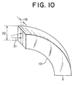
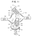
- Fig. 11 is a diagram showing a charged-particle beam irradiation apparatus in accordance with another embodiment of the present invention.
- the charged-particle beam irradiation apparatus shown in Fig. 1 uses electromagnets or the like to generate magnetic fields as a scanning field.
- the charged-particle beam irradiation apparatus 20 generates electric fields as a scanning field using two pairs of electrodes that are mutually facing with a gap between them.
- FIG. 11 there are shown electrodes 93a, 93b, 95a, and 95b, insulators 97 for supporting the electrodes, a box 102 made of a stainless steel for supporting the electrodes and insulators, power supplies 99a and 99b, cables 103 over which a voltage is supplied to the electrodes 93a, 93b, 95a, and 95b, cable connectors 105, and a motor 49 for rotating the box 102 via a rotary driving gear 53 having the box mounted thereon.
- the electrodes 93a, 93b, 95a, and 95b generate electric fields oriented in mutually opposite directions, whereby an incident charged-particle beam 31 is bent by the same angle in the mutually opposite directions. A beam parallel to the direction of incidence thereof is therefore swept all the time.
- spot scanning in which the spot of a beam parallel to the axis of incidence thereof is shifted two-dimensionally can be realized in the radiation area.
- the charged-particle beam irradiation apparatus of this embodiment may be employed as the charged-particle beam irradiation apparatus 20 included in the charged-particle beam rotary irradiation system of the second embodiment.
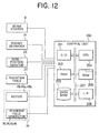
- Fig. 12 ia a diagram showing the configuration of a control portion of a charged-particle beam rotary irradiation system in accordance with the present invention.
- the control portion is responsible for control of, for example, the charged-particle beam rotary irradiation system shown in Fig. 9. A portion involved in controlling scan is extracted.
- a control unit 200 formed, for example, with a personal computer, an input/output (hereinafter I/O) control unit 201, a RAM 202 serving as a temporary memory, a database 203 for storing various kinds of information including the setting conditions for beam irradiation, a CPU 204 serving as a processor, a ROM 205 for storing a control program and others, an interface 206 for providing interface with another system, and a bus 207 over which the components are interconnected.
- I/O input/output
- a beam stopper 9 Connected to the control unit 200 are a beam stopper 9, an energy degrader 21, a dose/position monitor 23, a radiation table 27, motors 49, 49a, and 49b which are incorporated in the irradiation apparatus 20, and a scanning field generator equivalent to electromagnets 33 and 35 or electrodes 93a, 93b, 95a, and 95b.
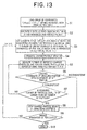
- Fig. 13 is a flowchart describing a control sequence employed in the control unit 200.
- the control unit 200 operates according to a program P describing the control sequence and residing in the ROM 205.
- a control operation will be described.
- step S2 The step S2 may be achieved by positioning the movable radiation table 27 or may require human labor.
- the angle of rotation and field intensity concerning the scanning electromagnets 33 and 35 are set according to the coordinates of the position to which a beam is irradiated ( ⁇ i, ri) (step S3).
- step S4 the charged-particle beam 31 is irradiated (step S4), and the number of incident particles contained in the charged-particle beam 31 and a position where the particles are deposited are measured using the dose/position monitor 23 (step S5).
- the coordinate of the position measured at step S5 is compared with the coordinate of the position set at step S3 (step S6). If they are inconsistent with each other, control is passed to step S8 of stopping the beam 31 which will be described later. If the result of comparison performed at step S6 reveals that the coordinate of the measured position is consistent with the coordinate of the set position, it is judged whether or not an integrated valued of numbers of particles measured at step S5 is equal to or larger than a pre-set number of particles at a given position (step S7). If the integrated value does not exceed, control is returned to step S5. If the integrated value exceeds, the charged-particle beam 31 is stopped using the beam stopper 9 (step S8).
- step S9 It is then judged whether or not irradiation should be terminated (step S9). If irradiation is continued, i is incremented by one, and control is returned to step S3. If irradiation should be terminated, it is terminated at step S10.
- steps S3 to S9 are executed repeatedly by assigning values ranging from 1 to n to i.
- the rotating speed of the scanning electromagnets 33 and 35 is lower than a scanning speed dependent on a magnetic field intensity or a scanning speed determined by the energy degrader 21.
- the thickness of the energy degrader 21 is changed. Any other means for changing an energy level, for example, a synchrotron particle accelerator may be employed.
- a means for stopping a charged-particle beam has been described by taking the beam stopper 9 for instance. Any other beam stopping means (for example, stopping a particle accelerator) may be employed.
- any other system of coordinates that is a variant of the system of cylindrical coordinates may be adopted.
- the irradiation apparatus 20 including the scanning electromagnets 33 and 35 is used as a means for sweeping a charged-particle beam.
- This embodiment is not limited to the irradiation apparatus 20. Any other means for sweeping a charged-particle beam, for example, an irradiation apparatus 20 including the scanning electrodes employed in the third embodiment will do.
- Fig. 14 is a flowchart describing a control sequence employed in the control unit 200 shown in Fig. 12 according to another method.
- the initial energy level of the charged-particle beam 31 is held constant by setting the energy degrader 5 to a certain thickness.
- a control operation will be described.
- These coordinates of positions that are the coordinates of positions, Zi, indicating depths, the angles of rotation, ⁇ ij, at the depths, and the set, Iij(t), defining the scan pattern that is the characteristic curve relative to time concerning scan in a direction of a diameter or radius at the angles are used to express a three-dimensional radiation area.
- step S2 may be achieved by positioning the movable radiation table 27 or may require human labor.
- the charged-particle beam 31 is then irradiated (step S5).
- a current is supplied by a given number of times according to the scan pattern of a current flowing into the scanning electromagnets 33 and 35 which is set at step S4. Specifically, for example, a current is supplied to the scanning electromagnets 33 and 35 according to the pre-set scan pattern of a current, which is defined by Iij(t), during scan of a radius or diameter of a radiation area expressed in, for example, the system of cylindrical coordinates (step S6).
- the scan pattern of a current is controlled on the basis of a time-passing increase rate of the number of charged particles to be measured in real time by the dose/position monitor 23 at step S10 that will be described later.
- the desired distribution of numbers of of particles is attained.
- step S7 When a given number of scans are completed, the beam 31 is stopped using the beam stopper 9 (step S7). It is then judged whether or not irradiation should be terminated (step S8). If irradiation should be terminated, control is jumped to step S12 that will be described later. If it is judged at step S8 that irradiation is continued, it is judged whether or not a coordinate of a position indicating the next depth, Zi, should be specified (step S9). If the coordinate of the next position Zi is specified, i is incremented by one and j is reset to the initial value of 1. Control is then returned to step S3. If the coordinate of the next position Zi is not specified, j is incremented by one and control is returned to step S4.
- steps S3 to S9 and steps S3 to S8 are repeatedly executed by assigning values ranging from 1 to m to i and values ranging from 1 to n to j.
- the given radiation area is thus irradiated.
- step S10 The number of deposited charged particles and a position where the particles are deposited are measured by the dose/position monitor 23 during irradiation (step S10).
- the coordinate of the position measured at step S10 is compared with the coordinate of the position, ⁇ ij, set at step S4. If they are consistent with each other, control is returned to step S10. If they are inconsistent with each other, the charged-particle beam 31 is stopped using the beam stopper 9 (step S8).
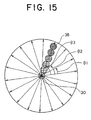
- Fig. 15 shows an example of a trajectory along which the spot of the charged-particle beam 31 is shifted according to the charged-particle beam irradiation method of this embodiment.
- Reference numeral 38 denotes the spot of the charged-particle beam 31 shifted.
- Fig. 15 is concerned with scan over the radius of a radiation area. Alternatively, the radiation area can be scanned over the diameter thereof.
- the scan pattern shown in Fig. 6 (scan over a radius) or Fig. 7 (scan over a diameter) may be adopted as the scan pattern defined by Iij(t).
- the flat density distribution of numbers of particles like the one shown in Fig. 4 can be attained.
- a sweeping speed at which a beam is swept as shown in Fig. 15 can be controlled so that it will be inversely proportional to the distance from the center axis of rotation. This is attributable to the fact that a current flowing into the electromagnets 33 and 35 and a distance by which a beam is swept away from the axis of incidence thereof have, as shown in Fig. 5, the relationship of inverse proportion.
- the relationship of inverse proportion between the sweeping speed and the distance from the center axis of rotation leads to the flat density distribution of numbers of particles shown in Fig. 4.
- the irradiation apparatus 20 including the scanning electromagnets 33 and 35 is used as a means for sweeping a charged-particle beam.
- This embodiment is not limited to the irradiation apparatus. Any other means for sweeping a charged-particle beam, for example, an irradiation apparatus 20 including the scanning electrodes employed in the third embodiment will do.
- a voltage to be applied to the irradiation apparatus 20 is varied according to the scan pattern Iij(t). That is to say, the scan pattern Iij(t) indicates a voltage as a function of time.
- the usage of the systems and method of the embodiments is not limited to the usage as a modality using a charged-particle beam but can apply to a wide range of fields, in which irradiation or injection of a charged-particle beam is required, including a field of semiconductors and a field of materials.
- a charged-particle beam irradiation apparatus comprises a scanning field generating means for generating a scanning field composed of a pair of fields effective in bending a charged-particle beam by the same angle in mutually opposite directions, and a rotating means for rotating the scanning field generating means with the axis of incidence of the charged-particle beam as a center. Consequently, there is provided a compact charged-particle beam irradiation apparatus realizing spot scanning in which the spot of a beam parallel the axis of incidence thereof is shifting in two axial directions.
- the scanning field generating means generates magnetic fields. Consequently, there is provided a compact charged-particle beam irradiation apparatus for generating a scanning magnetic field.
- the scanning field generating means generates electric fields. Consequently, there is provided a compact charged-particle beam irradiation apparatus for generating a scanning electric field.
- a charged-particle beam rotary irradiation system comprises: a deflecting means for deflecting a charged-particle beam so that the charged-particle beam will be perpendicular to a radiation plane; a charged-particle beam irradiation apparatus that includes a scanning field generator, placed downstream of the deflecting means, for generating a scanning field composed of a pair of fields effective in bending the charged-particle beam by the same angle in mutually opposite directions, and a rotator for rotating the scanning field generator with the axis of incidence of the charged-particle beam as a center, and that sweeps the charged-particle beam deflected by the deflecting means for the purpose of scan; a charged-particle beam energy adjusting means interposed between the charged-particle beam irradiation apparatus and an irradiated subject; and a rotary motion means for rotating at least the deflecting means and charged-particle beam irradiation apparatus in one united body.
- the charged-particle beam falls on the deflecting means from the direction of the axis of rotation of the rotary motion means.
- the deflecting means includes three deflective electromagnets for deflecting the incident charged-particle beam three times by 90° with respect to a direction parallel to a radiation plane so that the charged-particle beam will be perpendicular to the radiation plane.
- the irradiated subject is positioned on the axis of rotation of the rotary motion means.
- the deflective electromagnets of the deflecting means are realized with superconducting electromagnets. Consequently, there is provided a more compact charged-particle beam rotary irradiation system.
- a charged-particle beam irradiation system comprises: a charged-particle beam irradiation apparatus that includes a scanning field generator for generating a scanning field composed of a pair of fields effective in bending a charged-particle beam by the same angle in mutually opposite directions, and a rotator for rotating the scanning field generator with the axis of incidence of the charged-particle beam as a center; a charged-particle beam energy adjusting means, interposed between the charged-particle beam irradiation apparatus and an irradiated subject, for adjusting the energy of a charged-particle beam; a dose/position measuring means, interposed between the charged-particle beam irradiation apparatus and irradiated subject, for monitoring the dose and position of an irradiated charged-particle beam; a means for stopping a charged-particle beam; and a control means, connected to the respective means, for controlling scan.
- the fourth means retains the angle of rotation of the scanning field generator at a certain value, the intensity of a field generated by the scanning field generator and the energy of a charged-particle beam are modified in given order, and thus the first to third means are actuated repeatedly. Consequently, there is provided a charged-particle beam irradiation system in which the total time required for irradiation is shortened by reducing the frequency of adjusting the angle of rotation that varies slowly.
- a charged-particle beam irradiation system comprises: a charged-particle beam irradiation apparatus that includes a scanning field generator for generating a scanning field composed of a pair of fields effective in bending a charged-particle beam by the same angle in mutually opposite directions, and a rotator for rotating the scanning field generator with the axis of incidence of the charged-particle beam as a center, and that sweeps the charged-particle beam for the purpose of scan; a charged-particle beam energy adjusting means, interposed between the charged-particle beam irradiation apparatus and an irradiated subject, for adjusting the energy of a charged-particle beam; a dose/position measuring means, interposed between the charged-particle beam irradiation apparatus and irradiated subject, for monitoring the does and position of an irradiated charged-particle beam; a means for stopping a charged-particle beam; and a control means, connected to the respective means, for controlling scan.
- Iij(t) ⁇ t is adopted as Iij(t) defining the scan pattern, that is, the characteristic curve relative to time to be followed by the scanning field generator. Consequently, there is provided a charged-particle beam irradiation system capable of irradiating a charged-particle beam more uniformly.
- the angle of rotation of the scanning field generating means is retained at a certain value, the intensity of a field generated by the scanning field generator and the energy of a charged-particle beam are modified in given order, and thus the first to third steps are repeated. Consequently, there is provided a charged-particle beam irradiation method effective in shortening the total time required for irradiation by reducing the frequency of adjusting the angle of rotation that varies slowly.
- the scanning field generating means shifts a beam spot along a radius alone of a radiation area during one beam spill for the purpose of scan, and Iij(t) ⁇ t is adopted as Iij(t) defining the scan pattern that is the characteristic curve relative to time. Consequently, there is provided a charged-particle beam irradiation method enabling more uniform irradiation.
Landscapes
- Health & Medical Sciences (AREA)
- Engineering & Computer Science (AREA)
- Biomedical Technology (AREA)
- Radiology & Medical Imaging (AREA)
- Animal Behavior & Ethology (AREA)
- Veterinary Medicine (AREA)
- Pathology (AREA)
- Nuclear Medicine, Radiotherapy & Molecular Imaging (AREA)
- Public Health (AREA)
- Life Sciences & Earth Sciences (AREA)
- General Health & Medical Sciences (AREA)
- High Energy & Nuclear Physics (AREA)
- Physics & Mathematics (AREA)
- General Engineering & Computer Science (AREA)
- Radiation-Therapy Devices (AREA)
- Recrystallisation Techniques (AREA)
- Electron Beam Exposure (AREA)
Claims (11)
- Bestrahlungsvorrichtung (20) zum Bestrahlen mit einem Strahl geladener Teilchen, die folgendes aufweist:dadurch gekennzeichnet, daß die Abtastfeld-Erzeugungseinrichtung (33, 35) aus einem Paar von Feldern besteht, die zum Beugen eines Strahls (31) geladener Teilchen um den gleichen Winkel in zueinander entgegengesetzten Richtungen wirksam sind, so daß ein zu seiner Auftreffrichtung (30) paralleler Strahl die ganze Zeit abgelenkt wird.eine Abtastfeld-Erzeugungseinrichtung (33, 35) zum Erzeugen eines Abtastfelds, undeine Dreheinrichtung (49, 53) zum Drehen der Abtastfeld-Erzeugungseinrichtung mit der Auftreffachse (30) des Strahls geladener Teilchen als einer Mitte,
- Bestrahlungsvorrichtung zum Bestrahlen mit einem Strahl geladener Teilchen nach Anspruch 1, wobei die Abtastfeld-Erzeugungseinrichtung magnetische Felder (34) erzeugt.
- Bestrahlungsvorrichtung zum Bestrahlen mit einem Strahl geladener Teilchen nach Anspruch 1, wobei die Abtastfeld-Erzeugungseinrichtung elektrische Felder erzeugt.
- Drehbares Bestrahlungssystem zum Bestrahlen mit einem Strahl geladener Teilchen, das folgendes aufweist:die Bestrahlungsvorrichtung zum Bestrahlen mit einem Strahl geladener Teilchen nach Anspruch 1;eine Ablenkeinrichtung (11, 13, 19) zum Ablenken eines Strahls geladener Teilchen, so daß der Strahl geladener Teilchen zu einer zu bestrahlenden Strahlungsebene senkrecht ist;eine Einstelleinrichtung (21) für die Energie des Strahls geladener Teilchen, die zwischen der Bestrahlungsvorrichtung zum Bestrahlen mit einem Strahl geladener Teilchen und einem bestrahlten Objekt angeordnet ist; undeine Drehbewegungseinrichtung (10) zum Drehen von mindestens der Ablenkeinrichtung und der Bestrahlungsvorrichtung zum Bestrahlen mit einem Strahl geladener Teilchen in einem einheitlichen Körper; wobeidie Bestrahlungsvorrichtung (20) zum Bestrahlen mit einem Strahl geladener Teilchen an der Abstromseite der Ablenkeinrichtung angeordnet ist, unddie Dreheinrichtung (49, 53) den von der Ablenkeinrichtung abgelenkten Strahl geladener Teilchen zum Zweck der Abtastung lenkt.
- Drehbares Bestrahlungssystem zum Bestrahlen mit einem Strahl geladener Teilchen nach Anspruch 4, wobei der Strahl geladener Teilchen aus der Richtung der Drehachse der Drehbewegungseinrichtung auf die Ablenkeinrichtung fällt, und die Ablenkeinrichtung drei Ablenk-Elektromagnete (11, 13, 19) aufweist, um einen auftreffenden Strahl geladener Teilchen dreimal um 90° in bezug auf eine Richtung parallel zu einer Strahlungsebene abzulenken, so daß der Strahl geladener Teilchen zu der Strahlungsebene senkrecht ist, und das bestrahlte Objekt auf der Drehachse (29) der Drehbewegungseinrichtung positioniert ist.
- Drehbares Bestrahlungssystem zum Bestrahlen mit einem Strahl geladener Teilchen nach Anspruch 5, wobei die Ablenk-Elektromagnete (11, 13, 19) der Ablenkeinrichtung mit supraleitenden Elektromagneten realisiert sind.
- Drehbares Bestrahlungssystem zum Bestrahlen mit einem Strahl geladener Teilchen, das folgendes aufweist:wobei die Dreheinrichtung (49, 53) den Strahl geladener Teilchen zum Zweck der Abtastung lenkt.die Bestrahlungsvorrichtung zum Bestrahlen mit einem Strahl geladener Teilchen nach Anspruch 1;eine Einstelleinrichtung (21) für die Energie eines Strahls geladener Teilchen, die zwischen der Bestrahlungsvorrichtung zum Bestrahlen mit einem Strahl geladener Teilchen und einem bestrahlten Objekt angeordnet ist, um die Energie eines Strahls geladener Teilchen einzustellen;eine Dosis-/Position-Meßeinrichtung (23), die zwischen der Bestrahlungsvorrichtung zum Bestrahlen mit einem Strahl geladener Teilchen und dem bestrahlten Objekt angeordnet ist, um die Dosis und die Position eines Bestrahlungsstrahls geladener Teilchen zu überwachen;eine Einrichtung (9) zum Stoppen eines Strahls geladener Teilchen;eine Steuereinrichtung (200), die mit jeder der genannten Einrichtungen verbunden ist, um die Abtastung auf der Basis von einem von einer Anzahl von aufgebrachten Teilchen eines Strahls geladener Teilchen und einer Anzahl von ausgeführten Abtastungen zu steuern; und
- Bestrahlungssystem zum Bestrahlen mit einem Strahl geladener Teilchen nach Anspruch 7, wobei die Steuereinrichtung folgendes aufweist:eine erste Einrichtung (Fig. 13, S3) zum Einstellen des Drehwinkels und der Feldstärke hinsichtlich des Abtastfeldgenerators und der Energie eines Strahls geladener Teilchen in Abhängigkeit von einer Gruppe von Koordinaten [Pi : i = 1, 2, ..., n] (i =1, also ein Anfangswert), die einen Strahlungsbereich definieren;eine zweite Einrichtung (S4) zum Bestrahlen mit einem Strahl geladener Teilchen in Abhängigkeit von der Einstellung;eine dritte Einrichtung (S5 bis S8), um dann, wenn die Anzahl aufgebrachter Teilchen eines Strahls geladener Teilchen gleich wie oder größer als eine voreingestellte Anzahl von Teilchen wird oder wenn eine Koordinate einer Position, auf die ein Strahl geladener Teilchen abgestrahlt wird, mit einer Koordinate einer voreingestellten Position nicht übereinstimmt, den Strahl geladener Teilchen zu stoppen; undeine vierte Einrichtung (S9), die dann, wenn ein Strahl geladener Teilchen gestoppt wird, beurteilt, ob die Bestrahlung des gesamten Bestrahlungsbereichs vollständig ist, die dann, wenn die Bestrahlung nicht vollständig ist, i um Eins inkrementiert, den Drehwinkel und die Feldstärke hinsichtlich des Abtastfeldgenerators und die Energie eines Strahls geladener Teilchen in einer gegebenen Reihenfolge modifiziert und somit die erste bis dritte Einrichtung wiederholt aktiviert, und die dann, wenn die Bestrahlung vollständig ist, die Bestrahlung beendet.
- Bestrahlungssystem zum Bestrahlen mit einem Strahl geladener Teilchen nach Anspruch 8, wobei die vierte Einrichtung den Drehwinkel des Abtastfeldgenerators auf einem bestimmten Wert hält, die Stärke eines von dem Abtastfeldgenerator erzeugten Felds und die Energie eines Strahls geladener Teilchen in einer gegebenen Reihenfolge modifiziert und somit die erste bis dritte Einrichtung wiederholt aktiviert.
- Bestrahlungssystem zum Bestrahlen mit einem Strahl geladener Teilchen nach Anspruch 7, wobei die Steuereinrichtung folgendes aufweist:eine erste Einrichtung (Fig. 14, S3) zum Einstellen der Energie eines abzustrahlenden Strahls geladener Teilchen in Abhängigkeit von einer Koordinate einer Position, die eine Tiefe bezeichnet, bis zu der ein Strahl abgestrahlt wird, Zi (i = 1, also ein Anfangswert), die in einer Gruppe von Koordinaten bezeichnet ist, [Zi, ij), i = 1, 2, ..., m, j = 1, 2, ..., n], die einen Bestrahlungsbereich definieren;eine zweite Einrichtung (S4) zum Bezeichnen des Drehwinkels des Abtastfeldgenerators in ij (j = 1, also ein Anfangswert) und zum Bezeichnen einer Menge, die ein Abtastmuster definiert, das eine charakteristische Kurve relativ zu der Zeit in Iij(t) ist;eine dritte Einrichtung (S5, S6) zum Bestrahlen mit einem Strahl geladener Teilchen in Abhängigkeit von der Einstellung und Spezifikation, zum Treiben des Abtastfeldgenerators in Abhängigkeit von dem Abtastmuster, das die charakteristische Kurve relativ zu der durch Iij(t) definierten Zeit ist, und somit zum Lenken eines Strahls geladener Teilchen, um eine gegebene Anzahl von Abtastungen zu erzielen;eine vierte Einrichtung (S10, S11) zum Beurteilen, parallel mit den durch die dritte Einrichtung erzielten Abtastungen, ob eine Koordinate einer Position, auf die ein Strahl geladener Teilchen abgestrahlt wird, mit einer Koordinate einer voreingestellten Position übereinstimmt;eine fünfte Einrichtung (S7), um dann, wenn die gegebene Anzahl von Abtastungen ausgeführt worden ist oder wenn die Koordinate der Position, auf die ein Strahl geladener Teilchen abgestrahlt wird, mit der Koordinate der voreingestellten Position nicht übereinstimmt, den Strahl geladener Teilchen zu stoppen; undeine sechste Einrichtung (S8), die dann, wenn ein Strahl geladener Teilchen gestoppt ist, beurteilt, ob die Bestrahlung des gesamten Bestrahlungsbereichs vollständig ist, die dann, wenn die Bestrahlung vollständig ist, die Bestrahlung beendet, die dann, wenn die Bestrahlung nicht vollständig ist, beurteilt, ob die Koordinate der Position, die eine Tiefe bezeichnet, bis zu der ein Strahl abgestrahlt wird, Zi, auf den nächsten Wert geändert werden sollte, die dann, wenn die Koordinate nicht geändert wird, j um Eins inkrementiert und die zweite bis fünfte Einrichtung wiederholt aktiviert, die dann, wenn die Koordinate geändert wird, i um Eins inkrementiert, j auf den Anfangswert 1 rückstellt und die erste bis fünfte Einrichtung wiederholt aktiviert.
- Bestrahlungssystem zum Bestrahlen mit einem Strahl geladener Teilchen nach Anspruch 10, wobei Iij(t)∝√t als Iij(t) angenommen wird, welches das Abtastmuster definiert, das die charakteristische Kurve relativ zu der Zeit ist, welcher der Abtastfeldgenerator folgen soll.
Applications Claiming Priority (3)
| Application Number | Priority Date | Filing Date | Title |
|---|---|---|---|
| JP28700397A JP3577201B2 (ja) | 1997-10-20 | 1997-10-20 | 荷電粒子線照射装置、荷電粒子線回転照射装置、および荷電粒子線照射方法 |
| JP28700397 | 1997-10-20 | ||
| JP287003/97 | 1997-10-20 |
Publications (3)
| Publication Number | Publication Date |
|---|---|
| EP0911064A2 EP0911064A2 (de) | 1999-04-28 |
| EP0911064A3 EP0911064A3 (de) | 1999-08-18 |
| EP0911064B1 true EP0911064B1 (de) | 2004-06-30 |
Family
ID=17711774
Family Applications (1)
| Application Number | Title | Priority Date | Filing Date |
|---|---|---|---|
| EP98116272A Expired - Lifetime EP0911064B1 (de) | 1997-10-20 | 1998-08-28 | Bestrahlungsvorrichtung und rotatives Bestrahlungssystem mit Hilfe von geladenen Teilchenstrahlen |
Country Status (5)
| Country | Link |
|---|---|
| US (1) | US6268610B1 (de) |
| EP (1) | EP0911064B1 (de) |
| JP (1) | JP3577201B2 (de) |
| AT (1) | ATE270127T1 (de) |
| DE (1) | DE69824806T2 (de) |
Cited By (12)
| Publication number | Priority date | Publication date | Assignee | Title |
|---|---|---|---|---|
| US7728311B2 (en) | 2005-11-18 | 2010-06-01 | Still River Systems Incorporated | Charged particle radiation therapy |
| US8003964B2 (en) | 2007-10-11 | 2011-08-23 | Still River Systems Incorporated | Applying a particle beam to a patient |
| US8581523B2 (en) | 2007-11-30 | 2013-11-12 | Mevion Medical Systems, Inc. | Interrupted particle source |
| US8791656B1 (en) | 2013-05-31 | 2014-07-29 | Mevion Medical Systems, Inc. | Active return system |
| US8927950B2 (en) | 2012-09-28 | 2015-01-06 | Mevion Medical Systems, Inc. | Focusing a particle beam |
| US8933650B2 (en) | 2007-11-30 | 2015-01-13 | Mevion Medical Systems, Inc. | Matching a resonant frequency of a resonant cavity to a frequency of an input voltage |
| US8952634B2 (en) | 2004-07-21 | 2015-02-10 | Mevion Medical Systems, Inc. | Programmable radio frequency waveform generator for a synchrocyclotron |
| US9155186B2 (en) | 2012-09-28 | 2015-10-06 | Mevion Medical Systems, Inc. | Focusing a particle beam using magnetic field flutter |
| US9185789B2 (en) | 2012-09-28 | 2015-11-10 | Mevion Medical Systems, Inc. | Magnetic shims to alter magnetic fields |
| US9301384B2 (en) | 2012-09-28 | 2016-03-29 | Mevion Medical Systems, Inc. | Adjusting energy of a particle beam |
| US9545528B2 (en) | 2012-09-28 | 2017-01-17 | Mevion Medical Systems, Inc. | Controlling particle therapy |
| US9962560B2 (en) | 2013-12-20 | 2018-05-08 | Mevion Medical Systems, Inc. | Collimator and energy degrader |
Families Citing this family (29)
| Publication number | Priority date | Publication date | Assignee | Title |
|---|---|---|---|---|
| BE1012358A5 (fr) * | 1998-12-21 | 2000-10-03 | Ion Beam Applic Sa | Procede de variation de l'energie d'un faisceau de particules extraites d'un accelerateur et dispositif a cet effet. |
| US6814694B1 (en) | 1999-06-25 | 2004-11-09 | Paul Scherrer Institut | Device for carrying out proton therapy |
| DE10010523C2 (de) | 2000-03-07 | 2002-08-14 | Schwerionenforsch Gmbh | Ionenstrahlanlage zur Bestrahlung von Tumorgewebe |
| JP2002210028A (ja) * | 2001-01-23 | 2002-07-30 | Mitsubishi Electric Corp | 放射線照射システム及び放射線照射方法 |
| EP1584353A1 (de) * | 2004-04-05 | 2005-10-12 | Paul Scherrer Institut | System zur Protonentherapie |
| JP4158931B2 (ja) * | 2005-04-13 | 2008-10-01 | 三菱電機株式会社 | 粒子線治療装置 |
| JP5143606B2 (ja) * | 2008-03-28 | 2013-02-13 | 住友重機械工業株式会社 | 荷電粒子線照射装置 |
| KR101083604B1 (ko) | 2008-03-28 | 2011-11-16 | 스미도모쥬기가이고교 가부시키가이샤 | 하전입자선 조사장치 |
| JP5374731B2 (ja) * | 2008-11-26 | 2013-12-25 | 独立行政法人日本原子力研究開発機構 | レーザー駆動粒子線照射装置およびレーザー駆動粒子線照射装置の動作方法 |
| JP5171700B2 (ja) * | 2009-03-17 | 2013-03-27 | 株式会社東芝 | 回転照射治療装置 |
| CN102612719B (zh) * | 2009-11-10 | 2014-02-19 | 三菱电机株式会社 | 粒子射线照射系统及粒子射线照射方法 |
| JP5653126B2 (ja) * | 2010-08-19 | 2015-01-14 | 三菱電機株式会社 | ビームスキャニング照射装置 |
| WO2014030207A1 (ja) | 2012-08-21 | 2014-02-27 | 三菱電機株式会社 | 走査電磁石用制御装置および粒子線治療装置 |
| CN108770178B (zh) | 2012-09-28 | 2021-04-16 | 迈胜医疗设备有限公司 | 磁场再生器 |
| WO2014052721A1 (en) | 2012-09-28 | 2014-04-03 | Mevion Medical Systems, Inc. | Control system for a particle accelerator |
| US10254739B2 (en) | 2012-09-28 | 2019-04-09 | Mevion Medical Systems, Inc. | Coil positioning system |
| CN104813749B (zh) | 2012-09-28 | 2019-07-02 | 梅维昂医疗系统股份有限公司 | 控制粒子束的强度 |
| US9730308B2 (en) | 2013-06-12 | 2017-08-08 | Mevion Medical Systems, Inc. | Particle accelerator that produces charged particles having variable energies |
| US10258810B2 (en) | 2013-09-27 | 2019-04-16 | Mevion Medical Systems, Inc. | Particle beam scanning |
| EP2853292B1 (de) * | 2013-09-30 | 2019-07-31 | Ion Beam Applications S.A. | Geladene Hadronstrahlabgabe |
| US10675487B2 (en) | 2013-12-20 | 2020-06-09 | Mevion Medical Systems, Inc. | Energy degrader enabling high-speed energy switching |
| US9661736B2 (en) | 2014-02-20 | 2017-05-23 | Mevion Medical Systems, Inc. | Scanning system for a particle therapy system |
| US9950194B2 (en) | 2014-09-09 | 2018-04-24 | Mevion Medical Systems, Inc. | Patient positioning system |
| US10786689B2 (en) | 2015-11-10 | 2020-09-29 | Mevion Medical Systems, Inc. | Adaptive aperture |
| EP3481503B1 (de) | 2016-07-08 | 2021-04-21 | Mevion Medical Systems, Inc. | Behandlungsplanung |
| IT201700008049A1 (it) * | 2017-01-25 | 2018-07-25 | De Tec Tor S R L | Apparato per la misura di fasci di particelle cariche, in particolare protoni o ioni, emessi da sistemi per radioterapia esterna e corrispondente procedimento di calibrazione |
| US11103730B2 (en) | 2017-02-23 | 2021-08-31 | Mevion Medical Systems, Inc. | Automated treatment in particle therapy |
| JP6940676B2 (ja) | 2017-06-30 | 2021-09-29 | メビオン・メディカル・システムズ・インコーポレーテッド | リニアモーターを使用して制御される構成可能コリメータ |
| JP7311620B2 (ja) | 2019-03-08 | 2023-07-19 | メビオン・メディカル・システムズ・インコーポレーテッド | 粒子線治療システムのためのコリメータおよびエネルギーデグレーダ |
Family Cites Families (6)
| Publication number | Priority date | Publication date | Assignee | Title |
|---|---|---|---|---|
| US4367411A (en) * | 1979-06-04 | 1983-01-04 | Varian Associates, Inc. | Unitary electromagnet for double deflection scanning of charged particle beam |
| DE3828639C2 (de) * | 1987-08-24 | 1994-08-18 | Mitsubishi Electric Corp | Strahlentherapiegerät |
| JPH078300B2 (ja) * | 1988-06-21 | 1995-02-01 | 三菱電機株式会社 | 荷電粒子ビームの照射装置 |
| US4968890A (en) * | 1988-07-18 | 1990-11-06 | Mitsubishi Denki Kabushiki Kaisha | Charged particle beam-dosimeter |
| JP3472657B2 (ja) * | 1996-01-18 | 2003-12-02 | 三菱電機株式会社 | 粒子線照射装置 |
| JPH11142600A (ja) * | 1997-11-12 | 1999-05-28 | Mitsubishi Electric Corp | 荷電粒子線照射装置及び照射方法 |
-
1997
- 1997-10-20 JP JP28700397A patent/JP3577201B2/ja not_active Expired - Fee Related
-
1998
- 1998-08-28 EP EP98116272A patent/EP0911064B1/de not_active Expired - Lifetime
- 1998-08-28 DE DE69824806T patent/DE69824806T2/de not_active Expired - Lifetime
- 1998-08-28 AT AT98116272T patent/ATE270127T1/de not_active IP Right Cessation
- 1998-09-02 US US09/146,036 patent/US6268610B1/en not_active Expired - Lifetime
Non-Patent Citations (1)
| Title |
|---|
| CHU W.T. ET AL: "Instrumentation for treatment of cancer using proton and light-ion beams", REVIEW OF SCIENTIFIC INSTRUMENTS, vol. 64, no. 8, August 1993 (1993-08-01), WOODBURY, NY, US, pages 2055 - 2122, XP000393868, DOI: doi:10.1063/1.1143946 * |
Cited By (18)
| Publication number | Priority date | Publication date | Assignee | Title |
|---|---|---|---|---|
| US8952634B2 (en) | 2004-07-21 | 2015-02-10 | Mevion Medical Systems, Inc. | Programmable radio frequency waveform generator for a synchrocyclotron |
| US8344340B2 (en) | 2005-11-18 | 2013-01-01 | Mevion Medical Systems, Inc. | Inner gantry |
| US9452301B2 (en) | 2005-11-18 | 2016-09-27 | Mevion Medical Systems, Inc. | Inner gantry |
| US8907311B2 (en) | 2005-11-18 | 2014-12-09 | Mevion Medical Systems, Inc. | Charged particle radiation therapy |
| US8916843B2 (en) | 2005-11-18 | 2014-12-23 | Mevion Medical Systems, Inc. | Inner gantry |
| US7728311B2 (en) | 2005-11-18 | 2010-06-01 | Still River Systems Incorporated | Charged particle radiation therapy |
| US8003964B2 (en) | 2007-10-11 | 2011-08-23 | Still River Systems Incorporated | Applying a particle beam to a patient |
| US8941083B2 (en) | 2007-10-11 | 2015-01-27 | Mevion Medical Systems, Inc. | Applying a particle beam to a patient |
| US8970137B2 (en) | 2007-11-30 | 2015-03-03 | Mevion Medical Systems, Inc. | Interrupted particle source |
| US8581523B2 (en) | 2007-11-30 | 2013-11-12 | Mevion Medical Systems, Inc. | Interrupted particle source |
| US8933650B2 (en) | 2007-11-30 | 2015-01-13 | Mevion Medical Systems, Inc. | Matching a resonant frequency of a resonant cavity to a frequency of an input voltage |
| US9155186B2 (en) | 2012-09-28 | 2015-10-06 | Mevion Medical Systems, Inc. | Focusing a particle beam using magnetic field flutter |
| US8927950B2 (en) | 2012-09-28 | 2015-01-06 | Mevion Medical Systems, Inc. | Focusing a particle beam |
| US9185789B2 (en) | 2012-09-28 | 2015-11-10 | Mevion Medical Systems, Inc. | Magnetic shims to alter magnetic fields |
| US9301384B2 (en) | 2012-09-28 | 2016-03-29 | Mevion Medical Systems, Inc. | Adjusting energy of a particle beam |
| US9545528B2 (en) | 2012-09-28 | 2017-01-17 | Mevion Medical Systems, Inc. | Controlling particle therapy |
| US8791656B1 (en) | 2013-05-31 | 2014-07-29 | Mevion Medical Systems, Inc. | Active return system |
| US9962560B2 (en) | 2013-12-20 | 2018-05-08 | Mevion Medical Systems, Inc. | Collimator and energy degrader |
Also Published As
| Publication number | Publication date |
|---|---|
| JP3577201B2 (ja) | 2004-10-13 |
| EP0911064A3 (de) | 1999-08-18 |
| US6268610B1 (en) | 2001-07-31 |
| JPH11114078A (ja) | 1999-04-27 |
| DE69824806T2 (de) | 2005-08-04 |
| DE69824806D1 (de) | 2004-08-05 |
| ATE270127T1 (de) | 2004-07-15 |
| EP0911064A2 (de) | 1999-04-28 |
Similar Documents
| Publication | Publication Date | Title |
|---|---|---|
| EP0911064B1 (de) | Bestrahlungsvorrichtung und rotatives Bestrahlungssystem mit Hilfe von geladenen Teilchenstrahlen | |
| US4767930A (en) | Method and apparatus for enlarging a charged particle beam | |
| US8269196B2 (en) | Heavy ion radiation therapy system with stair-step modulation | |
| US6218675B1 (en) | Charged particle beam irradiation apparatus | |
| Haberer et al. | Magnetic scanning system for heavy ion therapy | |
| US7763873B2 (en) | Ion radiation therapy system with variable beam resolution | |
| US20100176309A1 (en) | Ion radiation therapy system with rocking gantry motion | |
| US7947969B2 (en) | Stacked conformation radiotherapy system and particle beam therapy apparatus employing the same | |
| US20100059688A1 (en) | Method And Software For Irradiating A Target Volume With A Particle Beam And Device Implementing Same | |
| US7856086B2 (en) | X-ray generator | |
| JP4282198B2 (ja) | 粒子線照射装置 | |
| JPH11142600A (ja) | 荷電粒子線照射装置及び照射方法 | |
| US7977657B2 (en) | Ion radiation therapy system with distal gradient tracking | |
| US8076657B2 (en) | Ion radiation therapy system having magnetic fan beam former | |
| Weber et al. | Depth scanning for a conformal ion beam treatment of deep seated tumours | |
| EP2471579B1 (de) | Teilchenstrahlbestrahlungsvorrichtung | |
| US20020033456A1 (en) | Charged-particle beam irradiator and therapy system employing the same | |
| JP2011212395A (ja) | 治療計画装置及び治療計画装置の治療計画を用いた粒子線治療装置 | |
| JP2009039353A (ja) | 荷電粒子照射装置とその制御方法 | |
| US12263354B2 (en) | Computer program product and computer system for planning and delivering radiotherapy treatment and a method of planning radiotherapy treatment | |
| JPH10300899A (ja) | 放射線治療装置 | |
| US7109502B1 (en) | Device for irradiating a target with a hadron-charged beam, use in hadrontherapy | |
| JP2001061978A (ja) | 粒子線照射方法及びその装置並びに粒子線治療装置 | |
| JP2006212081A (ja) | 粒子線照射装置 | |
| Alonso | Magnetically scanned ion beams for radiation therapy |
Legal Events
| Date | Code | Title | Description |
|---|---|---|---|
| PUAI | Public reference made under article 153(3) epc to a published international application that has entered the european phase |
Free format text: ORIGINAL CODE: 0009012 |
|
| AK | Designated contracting states |
Kind code of ref document: A2 Designated state(s): AT BE CH DE FR GB IT LI NL SE |
|
| AX | Request for extension of the european patent |
Free format text: AL;LT;LV;MK;RO;SI |
|
| PUAL | Search report despatched |
Free format text: ORIGINAL CODE: 0009013 |
|
| AK | Designated contracting states |
Kind code of ref document: A3 Designated state(s): AT BE CH CY DE DK ES FI FR GB GR IE IT LI LU MC NL PT SE |
|
| AX | Request for extension of the european patent |
Free format text: AL;LT;LV;MK;RO;SI |
|
| RIC1 | Information provided on ipc code assigned before grant |
Free format text: 6A 61N 5/00 A, 6G 21K 1/093 B |
|
| 17P | Request for examination filed |
Effective date: 19990824 |
|
| AKX | Designation fees paid |
Free format text: AT BE CH DE FR GB IT LI NL SE |
|
| 17Q | First examination report despatched |
Effective date: 20030513 |
|
| RIC1 | Information provided on ipc code assigned before grant |
Ipc: 7G 21K 1/093 B Ipc: 7A 61N 5/10 B Ipc: 7A 61N 5/00 A |
|
| GRAP | Despatch of communication of intention to grant a patent |
Free format text: ORIGINAL CODE: EPIDOSNIGR1 |
|
| RIC1 | Information provided on ipc code assigned before grant |
Ipc: 7G 21K 1/093 B Ipc: 7A 61N 5/10 B Ipc: 7A 61N 5/00 A |
|
| RTI1 | Title (correction) |
Free format text: CHARGED-PARTICLE BEAM IRRADIATION APPARATUS AND CHARGED-PARTICLE BEAM ROTARY IRRADIATION SYSTEM |
|
| GRAS | Grant fee paid |
Free format text: ORIGINAL CODE: EPIDOSNIGR3 |
|
| GRAA | (expected) grant |
Free format text: ORIGINAL CODE: 0009210 |
|
| AK | Designated contracting states |
Kind code of ref document: B1 Designated state(s): AT BE CH DE FR GB IT LI NL SE |
|
| PG25 | Lapsed in a contracting state [announced via postgrant information from national office to epo] |
Ref country code: NL Free format text: LAPSE BECAUSE OF FAILURE TO SUBMIT A TRANSLATION OF THE DESCRIPTION OR TO PAY THE FEE WITHIN THE PRESCRIBED TIME-LIMIT Effective date: 20040630 Ref country code: LI Free format text: LAPSE BECAUSE OF FAILURE TO SUBMIT A TRANSLATION OF THE DESCRIPTION OR TO PAY THE FEE WITHIN THE PRESCRIBED TIME-LIMIT Effective date: 20040630 Ref country code: CH Free format text: LAPSE BECAUSE OF FAILURE TO SUBMIT A TRANSLATION OF THE DESCRIPTION OR TO PAY THE FEE WITHIN THE PRESCRIBED TIME-LIMIT Effective date: 20040630 Ref country code: BE Free format text: LAPSE BECAUSE OF FAILURE TO SUBMIT A TRANSLATION OF THE DESCRIPTION OR TO PAY THE FEE WITHIN THE PRESCRIBED TIME-LIMIT Effective date: 20040630 Ref country code: AT Free format text: LAPSE BECAUSE OF FAILURE TO SUBMIT A TRANSLATION OF THE DESCRIPTION OR TO PAY THE FEE WITHIN THE PRESCRIBED TIME-LIMIT Effective date: 20040630 |
|
| REG | Reference to a national code |
Ref country code: GB Ref legal event code: FG4D Ref country code: CH Ref legal event code: EP |
|
| REF | Corresponds to: |
Ref document number: 69824806 Country of ref document: DE Date of ref document: 20040805 Kind code of ref document: P |
|
| PG25 | Lapsed in a contracting state [announced via postgrant information from national office to epo] |
Ref country code: SE Free format text: LAPSE BECAUSE OF FAILURE TO SUBMIT A TRANSLATION OF THE DESCRIPTION OR TO PAY THE FEE WITHIN THE PRESCRIBED TIME-LIMIT Effective date: 20040930 |
|
| REG | Reference to a national code |
Ref country code: GB Ref legal event code: 727 |
|
| NLV1 | Nl: lapsed or annulled due to failure to fulfill the requirements of art. 29p and 29m of the patents act | ||
| REG | Reference to a national code |
Ref country code: CH Ref legal event code: PL |
|
| ET | Fr: translation filed | ||
| REG | Reference to a national code |
Ref country code: GB Ref legal event code: 727A |
|
| PLBE | No opposition filed within time limit |
Free format text: ORIGINAL CODE: 0009261 |
|
| STAA | Information on the status of an ep patent application or granted ep patent |
Free format text: STATUS: NO OPPOSITION FILED WITHIN TIME LIMIT |
|
| REG | Reference to a national code |
Ref country code: GB Ref legal event code: 727B |
|
| 26N | No opposition filed |
Effective date: 20050331 |
|
| REG | Reference to a national code |
Ref country code: GB Ref legal event code: 727H |
|
| REG | Reference to a national code |
Ref country code: GB Ref legal event code: 746 Effective date: 20110513 |
|
| REG | Reference to a national code |
Ref country code: DE Ref legal event code: R084 Ref document number: 69824806 Country of ref document: DE Effective date: 20110506 Ref country code: DE Ref legal event code: R084 Ref document number: 69824806 Country of ref document: DE Effective date: 20110630 |
|
| PGFP | Annual fee paid to national office [announced via postgrant information from national office to epo] |
Ref country code: GB Payment date: 20110824 Year of fee payment: 14 Ref country code: FR Payment date: 20110818 Year of fee payment: 14 |
|
| PGFP | Annual fee paid to national office [announced via postgrant information from national office to epo] |
Ref country code: IT Payment date: 20110822 Year of fee payment: 14 |
|
| GBPC | Gb: european patent ceased through non-payment of renewal fee |
Effective date: 20120828 |
|
| REG | Reference to a national code |
Ref country code: FR Ref legal event code: ST Effective date: 20130430 |
|
| PG25 | Lapsed in a contracting state [announced via postgrant information from national office to epo] |
Ref country code: IT Free format text: LAPSE BECAUSE OF NON-PAYMENT OF DUE FEES Effective date: 20120828 |
|
| PG25 | Lapsed in a contracting state [announced via postgrant information from national office to epo] |
Ref country code: GB Free format text: LAPSE BECAUSE OF NON-PAYMENT OF DUE FEES Effective date: 20120828 |
|
| PG25 | Lapsed in a contracting state [announced via postgrant information from national office to epo] |
Ref country code: FR Free format text: LAPSE BECAUSE OF NON-PAYMENT OF DUE FEES Effective date: 20120831 |
|
| PGFP | Annual fee paid to national office [announced via postgrant information from national office to epo] |
Ref country code: DE Payment date: 20170822 Year of fee payment: 20 |
|
| REG | Reference to a national code |
Ref country code: DE Ref legal event code: R071 Ref document number: 69824806 Country of ref document: DE |