EP0910292B1 - Handstück für ein multifunktionales endoskopisches operationsgerät sowie ein derartiges operationsgerät - Google Patents
Handstück für ein multifunktionales endoskopisches operationsgerät sowie ein derartiges operationsgerät Download PDFInfo
- Publication number
- EP0910292B1 EP0910292B1 EP98902939A EP98902939A EP0910292B1 EP 0910292 B1 EP0910292 B1 EP 0910292B1 EP 98902939 A EP98902939 A EP 98902939A EP 98902939 A EP98902939 A EP 98902939A EP 0910292 B1 EP0910292 B1 EP 0910292B1
- Authority
- EP
- European Patent Office
- Prior art keywords
- handpiece
- handpiece according
- sonotrode
- ultrasonic
- housing
- Prior art date
- Legal status (The legal status is an assumption and is not a legal conclusion. Google has not performed a legal analysis and makes no representation as to the accuracy of the status listed.)
- Expired - Lifetime
Links
Images


Classifications
-
- B—PERFORMING OPERATIONS; TRANSPORTING
- B06—GENERATING OR TRANSMITTING MECHANICAL VIBRATIONS IN GENERAL
- B06B—METHODS OR APPARATUS FOR GENERATING OR TRANSMITTING MECHANICAL VIBRATIONS OF INFRASONIC, SONIC, OR ULTRASONIC FREQUENCY, e.g. FOR PERFORMING MECHANICAL WORK IN GENERAL
- B06B3/00—Methods or apparatus specially adapted for transmitting mechanical vibrations of infrasonic, sonic, or ultrasonic frequency
-
- A—HUMAN NECESSITIES
- A61—MEDICAL OR VETERINARY SCIENCE; HYGIENE
- A61B—DIAGNOSIS; SURGERY; IDENTIFICATION
- A61B17/00—Surgical instruments, devices or methods
- A61B17/22—Implements for squeezing-off ulcers or the like on inner organs of the body; Implements for scraping-out cavities of body organs, e.g. bones; for invasive removal or destruction of calculus using mechanical vibrations; for removing obstructions in blood vessels, not otherwise provided for
- A61B17/22004—Implements for squeezing-off ulcers or the like on inner organs of the body; Implements for scraping-out cavities of body organs, e.g. bones; for invasive removal or destruction of calculus using mechanical vibrations; for removing obstructions in blood vessels, not otherwise provided for using mechanical vibrations, e.g. ultrasonic shock waves
- A61B17/22012—Implements for squeezing-off ulcers or the like on inner organs of the body; Implements for scraping-out cavities of body organs, e.g. bones; for invasive removal or destruction of calculus using mechanical vibrations; for removing obstructions in blood vessels, not otherwise provided for using mechanical vibrations, e.g. ultrasonic shock waves in direct contact with, or very close to, the obstruction or concrement
-
- A—HUMAN NECESSITIES
- A61—MEDICAL OR VETERINARY SCIENCE; HYGIENE
- A61B—DIAGNOSIS; SURGERY; IDENTIFICATION
- A61B18/00—Surgical instruments, devices or methods for transferring non-mechanical forms of energy to or from the body
- A61B18/04—Surgical instruments, devices or methods for transferring non-mechanical forms of energy to or from the body by heating
- A61B18/12—Surgical instruments, devices or methods for transferring non-mechanical forms of energy to or from the body by heating by passing a current through the tissue to be heated, e.g. high-frequency current
- A61B18/14—Probes or electrodes therefor
-
- A—HUMAN NECESSITIES
- A61—MEDICAL OR VETERINARY SCIENCE; HYGIENE
- A61B—DIAGNOSIS; SURGERY; IDENTIFICATION
- A61B17/00—Surgical instruments, devices or methods
- A61B2017/00017—Electrical control of surgical instruments
- A61B2017/00022—Sensing or detecting at the treatment site
-
- A—HUMAN NECESSITIES
- A61—MEDICAL OR VETERINARY SCIENCE; HYGIENE
- A61B—DIAGNOSIS; SURGERY; IDENTIFICATION
- A61B17/00—Surgical instruments, devices or methods
- A61B17/22—Implements for squeezing-off ulcers or the like on inner organs of the body; Implements for scraping-out cavities of body organs, e.g. bones; for invasive removal or destruction of calculus using mechanical vibrations; for removing obstructions in blood vessels, not otherwise provided for
- A61B17/22004—Implements for squeezing-off ulcers or the like on inner organs of the body; Implements for scraping-out cavities of body organs, e.g. bones; for invasive removal or destruction of calculus using mechanical vibrations; for removing obstructions in blood vessels, not otherwise provided for using mechanical vibrations, e.g. ultrasonic shock waves
- A61B17/22012—Implements for squeezing-off ulcers or the like on inner organs of the body; Implements for scraping-out cavities of body organs, e.g. bones; for invasive removal or destruction of calculus using mechanical vibrations; for removing obstructions in blood vessels, not otherwise provided for using mechanical vibrations, e.g. ultrasonic shock waves in direct contact with, or very close to, the obstruction or concrement
- A61B2017/22014—Implements for squeezing-off ulcers or the like on inner organs of the body; Implements for scraping-out cavities of body organs, e.g. bones; for invasive removal or destruction of calculus using mechanical vibrations; for removing obstructions in blood vessels, not otherwise provided for using mechanical vibrations, e.g. ultrasonic shock waves in direct contact with, or very close to, the obstruction or concrement the ultrasound transducer being outside patient's body; with an ultrasound transmission member; with a wave guide; with a vibrated guide wire
- A61B2017/22015—Implements for squeezing-off ulcers or the like on inner organs of the body; Implements for scraping-out cavities of body organs, e.g. bones; for invasive removal or destruction of calculus using mechanical vibrations; for removing obstructions in blood vessels, not otherwise provided for using mechanical vibrations, e.g. ultrasonic shock waves in direct contact with, or very close to, the obstruction or concrement the ultrasound transducer being outside patient's body; with an ultrasound transmission member; with a wave guide; with a vibrated guide wire with details of the transmission member
- A61B2017/22018—Implements for squeezing-off ulcers or the like on inner organs of the body; Implements for scraping-out cavities of body organs, e.g. bones; for invasive removal or destruction of calculus using mechanical vibrations; for removing obstructions in blood vessels, not otherwise provided for using mechanical vibrations, e.g. ultrasonic shock waves in direct contact with, or very close to, the obstruction or concrement the ultrasound transducer being outside patient's body; with an ultrasound transmission member; with a wave guide; with a vibrated guide wire with details of the transmission member segmented along its length
-
- A—HUMAN NECESSITIES
- A61—MEDICAL OR VETERINARY SCIENCE; HYGIENE
- A61B—DIAGNOSIS; SURGERY; IDENTIFICATION
- A61B17/00—Surgical instruments, devices or methods
- A61B17/32—Surgical cutting instruments
- A61B17/320068—Surgical cutting instruments using mechanical vibrations, e.g. ultrasonic
- A61B2017/320072—Working tips with special features, e.g. extending parts
- A61B2017/320078—Tissue manipulating surface
-
- A—HUMAN NECESSITIES
- A61—MEDICAL OR VETERINARY SCIENCE; HYGIENE
- A61B—DIAGNOSIS; SURGERY; IDENTIFICATION
- A61B17/00—Surgical instruments, devices or methods
- A61B17/32—Surgical cutting instruments
- A61B17/320068—Surgical cutting instruments using mechanical vibrations, e.g. ultrasonic
- A61B2017/320088—Surgical cutting instruments using mechanical vibrations, e.g. ultrasonic with acoustic insulation, e.g. elements for damping vibrations between horn and surrounding sheath
-
- A—HUMAN NECESSITIES
- A61—MEDICAL OR VETERINARY SCIENCE; HYGIENE
- A61B—DIAGNOSIS; SURGERY; IDENTIFICATION
- A61B2217/00—General characteristics of surgical instruments
- A61B2217/002—Auxiliary appliance
- A61B2217/005—Auxiliary appliance with suction drainage system
Definitions
- the invention relates to a handpiece for a multifunctional endoscopic operating device, according to the preamble of the claim.
- handpieces for multifunctional endoscopic surgical equipment that a housing, connecting means disposed on the housing are, and those with leads, such as electric Lines, fluid supply and discharge lines, etc. are connectable, at least one ultrasonic transducer, which is arranged in the housing, an ultrasonic sonotrode, the ultrasonic energy to the distal end leads, and at least one switching device for Have control of functions of the handpiece.
- US-A-3 433 226 describes an endoscope catheter with an ultrasonic transducer and an associated sonotrode for transmitting vibrational energy for the purpose of medical treatment.
- the converter is with High frequency operable and the sonotrode consists of metallurgical with each other connected acoustic coupling members, the liquid-conducting Form hollow channel, the end member is preferably flexible and in operation whose end is formed a vibro-belly.
- a housing can be used as a handle be formed and preferably surrounds the transducer, wherein plug connections are provided to coils of the converter to the housing. Switches will not described.
- the endoscope described in US-A-5 391 144 is a multifunctional surgical device, which has an ultrasonic function and a high-frequency function.
- a handpiece contains an ultrasonic generator and is interchangeable with made of a titanium alloy sonotrodes connectable, with an elongated Sonotrode of several welded together tubular pieces may be composed, which form a continuous channel, wherein the joints and the end of the sonotrode at the antinodes the ultrasonic vibration are.
- a radio frequency line extends through the housing and is connected to the sonotrode. Circuits of the ultrasonic generator are controlled by switches provided on the housing are, of which also one can be operated with the foot.
- One in a recess the housing wall inserted switch includes a push button to the underside of which a first contact element is attached, which upon actuation the push button with a second bottom attached to the recess Contact element is brought into contact.
- a handpiece according to the preamble of Claim 1 in which, in order to increase the security for the User and the person treated the switching device reliable insulated against high frequency to the outside.
- the service life of the known sonotrodes is particular when the probe parts are long, comparatively short, as they are usually made of steel wire are.
- a sonotrode used that a long and thin probe part having a channel, the consists of several pieces that welded together are.
- the welds can become involved in particular in the antinodes of the ultrasonic wave are located.
- the drilled pieces of pipe are preferably turned on so that they are self-centering can be welded.
- the sonotrode in a conventional manner have a thickening, which welded to the probe part and bolted to the housing.
- a thickening which welded to the probe part and bolted to the housing.
- connection means which at one end of the handpiece or of the housing is connected.
- connection lines which are not disposable lines disposable lines typically fluid lines - are executed in introduced a cable sheath. This allows a particularly easy handling of the handpiece.
- ultrasonic transducer may preferably piezoelectric transducer be used.
- momentum in the piezo transducers in the prior art usually to the electrical mass are laid, it is common to one even number of piezo discs and thus an odd one Number of electrode surfaces to use.
- all the piezo disks of the Be isolated flywheel With an even number of electrode surfaces, i. with the same number of positive ones as negative surfaces compensate each other substantially the positive and negative currents, the capacitive to Coupling flywheel and therefore by touch to Patients can arrive.
- the ultrasonic generator has a floating, balanced output, so that due to the even number of electrode areas For reasons of symmetry, the capacitive to the patient coupled currents to a minimum leakage current compensate.
- the Switching device has at least one switching sensor and at least one actuating element, wherein the actuating element has no part with the switch sensor can be brought into direct mechanical contact. In particular, this is also no electrical connection made so that a high frequency coupling already essentially between switch and actuator is avoided.
- a magnet is placed inside the hermetically sealed housing, for example a Reed contact or a Hall probe for the ultrasound function on.
- the handpiece can be designed such that the actuating element comprises a magnet whose Magnetic field by actuation of the actuator at the location of the switch changes, and that the switch Depending on the magnetic field closes or opens.
- the switching device having an actuator with which not only Switching functions can be performed, but with which also varies properties of a circuit can be.
- actuator with which not only Switching functions can be performed, but with which also varies properties of a circuit can be.
- Functions can be varied by the actuator. These functions are for example the amplitude, Turning on or off the flush, variation the suction pressure, etc.
- the circuit resonant circuits with different Have resonant frequencies; by pressing of the actuating element is in each case at least a resonant circuit activated.
- a circuit arranged which makes the commands inductive transmits into the housing interior Outside or in the housing wall and inside the housing are for example Induction coils arranged.
- This will the outer coil is part of a resonant circuit by being via key contacts with different capacitors is switched in parallel. It is created for every desired Function a characteristic resonance frequency.
- the inner coil serves as a sensor for the resonance frequency of the resonant circuit. A circuit detects this frequency and derives the appropriate command further.
- the two lines For example, for the power-on function as well for temperature monitoring in the handpiece and the Handpiece type coding can be used.
- the Handpiece type coding is For example, built with diodes a network that in the one direction of the current the reed switch and in the Opposite direction the temperature via a thermostat switch queries.
- the coding is by additional Elements, such as a serially connected to the thermostat Resistance set.
- Normalized is an air gap for the separation of 5000 Vss of 16 mm and a creepage distance of 23 mm.
- the isolation between High frequency and ultrasonic power supply in the handpiece laid or the ultrasonic generator isolated executed.
- the insulation takes place at least partially with a shrink tube (polyvinylidene fluoride (PVDF), silicone etc.) and / or one Isolation ring.
- a shrink tube polyvinylidene fluoride (PVDF), silicone etc.
- the housing of the handpiece made of plastic.
- plastic has u.a. the advantage of being easy to isolate with low weight.
- PEEK is suitable as the plastic.
- This Plastic is fully sterilizable.
- a Another possibility is a composite plastic housing, for example, by a fiber winding technique, such as For example, glass, carbon, or Kevlar reinforced Plastic, is produced.
- the composite plastic housing are preferably thin-walled and thus have one small outer diameter and even lower weight.
- a change-over switch whose actuation causes that the function of the suction and purge lines reversed becomes. It can happen during an operation be advantageous if the flushing channel used for aspiration For example, if the suction channel as an instrument channel is used. Even with clogged Suction line may be in the short term during surgery Swapping the flushing and suction lines to remedy the situation. Is further rinsed by the suction, so creates a directed beam, which at the same time Ultrasound has a multiple range (namely about 30 cm) and partially nebulised.
- nodes Distance less than ⁇ / 8
- the horn of a sonotrode at the Tip trimmed until it is on the right frequency swings.
- the horn is however not defined in length and therefore not always defined with a coat surrounding the horn Length can be combined.
- the mantle be Horn is adjusted.
- the resonance frequency becomes, for example increased when the outside diameter at the Coupling point, so turned off on a vibration belly becomes what causes a reduction of the flywheel. The frequency gets lower, if at a node is turned off because the spring constant is so reduced becomes.
- an ablation-enhancing element is.
- This can be in particular a ring jacket, the is designed as a cutting Schlingring. there the ring jacket can also be attached to a probe be that has no hole.
- the annular jacket is welded to the sonotrode.
- the tip of the sonotrode and / or the ring coat surface treated or made of tungsten carbide is suitable especially for the removal of hard stones. It can also be a carbide insert soldered or be welded.
- a suction is still used, which is straight.
- the straight course allows the Use of the suction line as instrument channel and / or the introduction of observation optics and / or a light guide for laser treatments.
- the invention is preferred in a multifunctional endoscopic surgical device with an ultrasound function for smashing tissue, a high frequency function for additional cutting and / or Coagulating, and a rinsing and / or suction function realized.
- the functions are provided by the user controlled with a handpiece according to the invention. it Fabric is liquefied or crushed or in the area sucked and demolished the mouth.
- smashing tissue By smashing tissue is meant that tissue liquefied or downsized and in the area rather Mouth sucked and torn off. It will be volume or material removed. This allows the invention Also use handpiece indirectly for cutting with a cutting gap of 4 mm. The ring coat cuts without volume erosion. He becomes cockroach / planing ) Are used.
- the decoupling at least one inductive element and in particular done by a compensation coil.
- a compensation coil can be and so their magnetic fields in the core compensate.
- the coil suppresses the "common-mode" high frequency and is for the differential ultrasonic currents without effect.
- the live cables between ultrasonic generator and compensation coil discharged by capacity to earth.
- the HF voltage drop takes place here in the compensation coil.
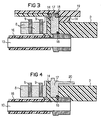
- FIGS. 2 to 5 indicate different possibilities the isolation between ultrasound and high frequency. In operation, it is especially in case of a defect, however also necessary in normal operation, the high frequency of to electrically isolate the ultrasound.
- a compensation coil used is the voltage across the insulation in the handpiece Normally only a fraction of the full high-frequency voltage. Between the mains and the patient must insulate their size from the highest applied voltage is derived.
- the insulation acts in the handpiece as additional security.
- a clamping nut 15 with an extension lip provided, which is wrapped with an insulating tape 13 is.
- the clamping nut 15 with its bolt 10th or its cylindrical edge are at high frequency.
- An insulation also finds a ceramic 11 and a silicone mass 14 instead. This will be a Silikonverguß 14 in the arrow direction through a filling opening 12a pressed until it is at the vent 12b exits.
- the suspension is made of insulating ceramic, for example 17 manufactured (see Fig. 3).
- the space between Front part 2 and housing wall 19 is for interruption the creepage with silicone 14 shed. Through this Measure are simultaneously damped transverse vibrations and ensures a rotation.
- the bolt 10 and the piezo 8 are through a silicone tube 16 isolated.
- the ends of the tube 16 are with the respective Ceramic parts 11 and 17 shed.
- the casting happens through appropriate injection and vents 12a and 12b.
- the silicone potting compound 14 goes with the tube 16 a perfect vulcanization-like Connection.
- the housing wall 19 is, for example made of plastic.
- FIG. 4 Another possibility of isolation on the suspension is shown in Fig. 4. There is the creepage with an insulation ring 20 extended.
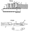
- Fig. 5 is a further possibility of isolation shown. Here it is Front part 2 wrapped with insulating tape 13. The kick-off point for ceramic suspension 17 is then with silicone compound 14 sealed.
- Fig. 6 is schematically a multifunctional endoscopic Operating device shown.
- the ultrasonic voltage generator 21 has a compensation coil 22 on.
- the leads from the ultrasonic voltage generator 21 as well as the line from the high-frequency generator 24 pass through a common cable 23 to the handpiece 25.
- the handpiece 25 are schematically the piezoelectric transducer, the reed relay and sonotrode 27 are shown. Further, a neutral electrode 26 is shown in FIG. 6 shown.
- the electrical connections (switching lines, high frequency, Ultrasound), in a common cable 23rd are integrated, are spliced at the proximal end in a part with ultrasonic and switching cables for the ultrasonic voltage generator and a Part with the high frequency line for the high frequency generator.
- the compensation coil 22 To the core of the compensation coil 22 are the four Lines (here 2 ultrasonic and 2 signal lines) wrapped so that the coil is the "common-mode" high frequency suppressed and the differential ultrasound and signal currents are not affected.
- Lines here 2 ultrasonic and 2 signal lines
- the handpiece according to the invention is particularly suitable for use with trocars where sonotrodes are used find that are stretched out in length.
- a sonotrode 27 is shown.
- Fig. 7 is at 28 a Screw thread indicated with the sonotrode is attached to the housing of the handpiece, so that in particular the coupling to the piezoelectric elements takes place.
- the sonotrode shown has a length of four half Wavelengths. In the antinodes are Welds attached.
- the sonotrode of Fig. 7 has at the near-patient end, a vibration abdomen.
- the welds are necessary as the used Titanium alloys not available as a suitable tube and the probes are drilled for this reason have to.
- Extended probes like those in find endoscopy application and, for example, in Trocars are to be used are from different Assembled pieces, since unilateral deep holes with reasonable error rate (20%) only up to 200 mm are possible.
- the welding technique is cost effective and reliable, i. there is little committee produced.
- a ring jacket attached to the probe tip Fig. 8 shows a side view of a Probe tip 30 with a ring jacket 31. Left is a cylindrical embodiment shown in FIG Fig. 9 is again listed in perspective. On 8, an annular jacket 31 is shown on the right side of FIG. the increased rigidity due to an exponential has a running shape. An increased stiffness is due to the very high acceleration and so that high load of material in the ultrasonic application necessary.
Landscapes
- Health & Medical Sciences (AREA)
- Engineering & Computer Science (AREA)
- Surgery (AREA)
- Mechanical Engineering (AREA)
- Life Sciences & Earth Sciences (AREA)
- Biomedical Technology (AREA)
- Nuclear Medicine, Radiotherapy & Molecular Imaging (AREA)
- Vascular Medicine (AREA)
- Orthopedic Medicine & Surgery (AREA)
- Heart & Thoracic Surgery (AREA)
- Medical Informatics (AREA)
- Molecular Biology (AREA)
- Animal Behavior & Ethology (AREA)
- General Health & Medical Sciences (AREA)
- Public Health (AREA)
- Veterinary Medicine (AREA)
- Surgical Instruments (AREA)
Abstract
Description
- endoskopische Anwendung,
- Ultraschallfunktion,
- Hochfrequenzkoagulation,
- Saugfunktion,
- Spülung,
- mehrere Anschlüsse im hinteren Bereich des Handstücks,
- Schalter am Handstück, und
- Dampfsterilisierbarkeit.
- Der Operateur wird durch den aufgesetzten Schalter und die separate Zuleitung gestört. Die separate Zuleitung wird darüberhinaus häufig beim Einsatz beschädigt.
- Bei integrierten Schaltern ist häufig eine Kabeldurchführung vorhanden, die mit konstruktivem Aufwand verbunden ist und beim Autoklavieren ein Leckrisiko darstellt. Aus diesem Grund wäre es wünschenswert, Durchführungen möglichst zu vermeiden.
- Bei eingeschalteter Hochfrequenz (üblicherweise 5000 Vss und 500 kHz) besteht die Gefahr eines Durchschlages. Sind in einem Kabel gemeinsam Hochfrequenzadern und weitere Adern vorhanden, so sind die weiteren Adern durch die kapazitive Kopplung auch auf Hochfrequenzpotential. Aus diesem Grund müssen Schalter zuverlässig gegen Hochfrequenz nach außen isoliert werden. Mit konstruktivem Aufbau ist dies zwar machbar, dabei müßten allerdings relativ große und auftragende Schalter verwendet werden. Kleine, wenig auftragende Schalter wie beispielsweise Folientaster, die auf dem Mantel angebracht sind, sind beim Stand der Technik nicht einsetzbar.
- Für jede Funktion, die mit dem Operationsgerät ausgeführt werden soll, ist jeweils ein Kabel zur Übertragung und Steuerung erforderlich.
Es zeigen:
- Fig. 1:
- Teil eines Handstücks in schematischer Darstellung mit Betätigungselement und Piezoelement,
- Fig. 2:
- Querschnitt durch einen Teil eines Handstücks,
- Fig. 3:
- Querschnitt durch einen anderen Teils eines Handstücks,
- Fig. 4:
- Wie Fig. 3 nur in anderer Ausführungsform,
- Fig. 5:
- Wie Figuren 3 und 4 in anderer Ausführungsform,
- Fig. 6:
- Übersichtsskizze eines erfindungsgemäßen Operationsgerätes mit Kompensationsspule,
- Fig. 7:
- Sonotrode mit einer Länge von 4*λ/2,
- Fig. 8:
- Sondenspitze mit Ringmantel (links in zylindrischer Ausgestaltung und rechts in exponentieller Ausgestaltung),
- Fig. 9:
- Sondenspitze mit Ringmantel in zylindrischerAusgestaltung in perspektivischer Darstellung.
- 1
- Gehäuse-Hinterteil
- 2
- Gehäuse-Vorderteil
- 3
- Magnet
- 4
- Feder
- 5
- Schieber
- 6
- Reed-Kontakt
- 7
- Piezoelemente
- 8
- Piezo
- 9
- Elektrode
- 10
- Bolzen
- 11
- Keramik
- 12
- Entlüftung
- 13
- Kapton
- 14
- Silikonmasse
- 15
- Spannmutter
- 16
- Silikonschlauch
- 17
- Keramikaufhängung
- 18
- O-Ring
- 19
- Kunststoff-Gehäusewand
- 20
- Isolationsring
- 21
- Ultraschallspannungsgenerator
- 22
- Kompensationsspule
- 23
- Kabel
- 24
- Hochfrequenzgenerator
- 25
- Handstück
- 26
- Patientenelektrode
- 27
- Sonotrode
- 28
- Schraubgewinde
- 29
- Schwingungsknoten
- 30
- Sondenspitze
- 31
- Ringmantel
- 32
- abgesetzte Bohrung
Claims (36)
- Handstück (25) für ein multifunktionales endoskopisches Operationsgerät, das mindestens eine Ultraschallfunktion aufweist, mitdadurch gekennzeichnet, dass die Schalteinrichtung wenigstens einen Schaltsensor aufweist, und dass das Betätigungselement kein Teil aufweist, das mit dem jeweiligen Schaltsensor in direktem mechanischen Kontakt bringbar ist.einem Gehäuse,Anschlussmitteln, die am Gehäuse angeordnet und mit elektrischen Leitungen sowie Flüssigkeitsleitungen verbindbar sind,wenigstens einem in dem Gehäuse angeordneten Ultraschall-Wandler (7),einer Ultraschall-Sonotrode (27), welche Ultraschallenergie zu einem distalen Ende des Operationsgeräts leitet, undmindestens einer ohne separate Zuleitung und Kabeldurchführungen am Handstück vorgesehenen Schalteinrichtung mit einem Betätigungselement und einem zugeordneten Schaltkreis zur Steuerung von Funktionen des Handstücks,
- Handstück nach Anspruch 1,
dadurch gekennzeichnet, dass die Sonotrode (27) einen langgestreckten Sondenteil mit einem Kanal aufweist, der aus mehreren Stücken besteht, die miteinander verschweißt sind, und dass die Schweißstellen sich in den Schwingungsbäuchen der Ultraschallwelle befinden. - Handstück nach Anspruch 1 oder 2,
dadurch gekennzeichnet, dass zumindest der Sondenteil aus Titan oder einer Titanverbindung besteht, und dass der Durchmesser des Kanals ca. 2 mm, die Dicke des Sondenteils weniger als 4 mm und die Länge mehr als 30 cm betragen. - Handstück nach einem der Ansprüche 1 bis 3,
dadurch gekennzeichnet, daß die Sonotrode proximalseitig eine Verdickung aufweist, die mit dem Sondenteil verschweißt und mit dem Gehäuse verschraubt ist. - Handstück nach einem der Ansprüche 1 bis 4,
dadurch gekennzeichnet, daß ein einziges Anschlußmittel vorgesehen ist, und
daß sämtliche Handstück-Anschlüsse der Anschlußleitungen an dem einen Anschlußmittel angebracht sind. - Handstück nach Anspruch 7,
dadurch gekennzeichnet, daß Informationen vom Betätigungselement magnetisch, induktiv, elektromagnetisch, optisch und/oder akustisch zum Schaltsensor übermittelt werden, der mit dem Schaltkreis verbunden ist. - Handstück nach Anspruch 6,
dadurch gekennzeichnet, daß das Betätigungselement einen Magneten (3) aufweist, dessen Magnetfeld am Ort des Schaltsensors sich durch Betätigung des Betätigungselementes ändert, und daß der Schaltsensor magnetfeldabhängig schließt bzw. öffnet. - Handstück nach Anspruch 6 oder 7,
dadurch gekennzeichnet, daß der Schaltsensor ein Reed-Relais oder eine Hall-Sonde ist. - Handstück nach einem der Ansprüche 1 bis 7,
dadurch gekennzeichnet, daß die Schalteinrichtung die Variation von Eigenschaften wenigstens eines Schaltkreises erlaubt. - Handstück nach Anspruch 8,
dadurch gekennzeichnet, daß das bzw. die Betätigungselemente Schwingkreise mit unterschiedlichen Resonanzfrequenzen aufweisen, und
daß durch Betätigen des Betätigungselementes jeweils mindestens ein Schwingkreis aktiviert wird. - Handstück nach Anspruch 9 oder 10,
dadurch gekennzeichnet, daß im Handstück eine Spule und eine Schaltung vorgesehen sind, die induktiv die Resonanzfrequenz des aktivierten Schwingkreises erfassen. - Handstück nach einem der Ansprüche 1 bis 11,
dadurch gekennzeichnet, daß in der Anschlußleitung nur zwei Signalleitungen für die Einschaltfunktion sowie weitere Funktionen, wie die Temperaturüberwachung und die Handstück-Kodierung vorgesehen sind. - Handstück nach einem der Ansprüche 1 bis 12,
dadurch gekennzeichnet, daß zusätzlich eine HF-Einrichtung vorgesehen ist. - Handstück nach Anspruch 13,
dadurch gekennzeichnet, daß zur Isolation zwischen Hochfrequenz- und Ultraschallversorgung im Handstück etwaige Kriechstrecken verlängert oder unterbrochen sind. - Handstück nach Anspruch 14,
dadurch gekennzeichnet, daß die Isolation zumindest teilweise mit einem PVDF-Schlauch und/oder einem Isolationsring erfolgt. - Handstück nach Anspruch 14 oder 15,
dadurch gekennzeichnet, daß es ein Gehäuse aus Kunststoff aufweist. - Handstück nach einem der Ansprüche 2 bis 16,
dadurch gekennzeichnet, daß der Kanal in der Sonotrode geradlinig durch das Handstück bis zu einem Fluid-Anschluß verläuft. - Handstück nach Anspruch 17,
dadurch gekennzeichnet, daß der Kanal zum Saugen oder Spülen dient. - Handstück nach Anspruch 18,
dadurch gekennzeichnet, daß ein Umschalter vorgesehen ist, durch dessen Betätigung von Absaugen auf Spülen und umgekehrt umgeschaltet wird. - Handstück nach einem der Ansprüche 1 bis 19,
dadurch gekennzeichnet, daß Befestigungen, Halterungen bzw. Ankopplungen von Schläuchen, Rohren, elektrischen Anschlüssen und/oder Dichtungen näher als λ/8 zu Schwingungsknoten angebracht sind. - Handstück nach einem der Ansprüche 1 bis 20,
dadurch gekennzeichnet, daß im Bereich des distalen (patientennahen) Endes der Sonotrode (27) ein abtragungsverstärkendes Element angeordnet ist. - Handstück nach Anspruch 21,
dadurch gekennzeichnet, daß das abtragungsverstärkende Element ein schneidender Schlingring ist. - Handstück nach Anspruch 22,
dadurch gekennzeichnet, daß die Mittelsenkrechte des schneidenden Schlingrings und die Symmetrieachse der Sonotrode (27) parallel zueinander angeordnet sind. - Handstück nach Anspruch 22 oder 23,
dadurch gekennzeichnet, daß der schneidende Schlingring in zumindest einer Projektion an der Befestigungsbasis breiter ist als im gegenüberliegenden Bereich. - Handstück nach Anspruch 24,
dadurch gekennzeichnet, daß die Kontur des Schlingrings einer exponentiellen oder quadratischen Kurve folgt. - Handstück nach einem der Ansprüche 22 bis 25,
dadurch gekennzeichnet, daß der Schlingring mit der Sonotrode (27) verschweißt ist. - Handstück nach einem der Ansprüche 1 bis 26,
dadurch gekennzeichnet, daß die Spitze der Sonotrode (27) und/oder die Schneide des Schlingrings aus Hartmetall bestehen und/oder beschichtet sind. - Handstück nach einem der Ansprüche 17 bis 27,
dadurch gekennzeichnet, daß die Absaugleitung als Instrumenten- und/oder Beobachtungskanal verwendet wird. - Handstück nach einem der Ansprüche 1 bis 28,
dadurch gekennzeichnet, daß vor einem Ultraschallgenerator (28), der die Spannungsversorgung für die Ultraschallfunktion bereitstellt, hochfrequente Signalanteile ausgekoppelt werden. - Handstück nach Anspruch 29,
dadurch gekennzeichnet, daß die hochfrequenten Signalanteile durch mindestens ein induktives Element ausgekoppelt werden. - Handstück nach Anspruch 30,
dadurch gekennzeichnet, daß eine Kompensationsspule (22) als induktives Element dient. - Handstück nach Anspruch 31,
dadurch gekennzeichnet, daß die spannungsführenden Kabel um den Kern der Kompensationsspule (22) gewickelt sind und sich deren Magnetfelder im Kern kompensieren. - Handstück nach einem der Ansprüche 30 bis 32,
dadurch gekennzeichnet, die spannungsführenden Kabel durch Kapazitäten gegen Erde gedämpft sind. - Handstück nach einem der Ansprüche 1 bis 33,
dadurch gekennzeichnet, daß der Ultraschall-Wandler aus Piezoscheiben besteht. - Handstück nach Anspruch 34,
dadurch gekennzeichnet, daß die Zahl der Piezoscheiben gerade'ist, und
daß die Piezoscheiben von der Schwungmasse isoliert sind. - Handstück nach Anspruch 34 oder 35,
dadurch gekennzeichnet, daß der Generator (21) der den Ultraschall-Wandler ansteuert, einen floatenden symmetrischen Ausgang aufweist.
Applications Claiming Priority (3)
| Application Number | Priority Date | Filing Date | Title |
|---|---|---|---|
| DE19700270A DE19700270A1 (de) | 1997-01-07 | 1997-01-07 | Handstück für ein multifunktionales endoskopisches Operationsgerät sowie ein derartiges Operationsgerät |
| DE19700270 | 1997-01-07 | ||
| PCT/DE1998/000041 WO1998030155A1 (de) | 1997-01-07 | 1998-01-07 | Handstück für ein multifunktionales endoskopisches operationsgerät sowie ein derartiges operationsgerät |
Publications (2)
| Publication Number | Publication Date |
|---|---|
| EP0910292A1 EP0910292A1 (de) | 1999-04-28 |
| EP0910292B1 true EP0910292B1 (de) | 2005-07-20 |
Family
ID=7816897
Family Applications (1)
| Application Number | Title | Priority Date | Filing Date |
|---|---|---|---|
| EP98902939A Expired - Lifetime EP0910292B1 (de) | 1997-01-07 | 1998-01-07 | Handstück für ein multifunktionales endoskopisches operationsgerät sowie ein derartiges operationsgerät |
Country Status (4)
| Country | Link |
|---|---|
| US (1) | US6171265B1 (de) |
| EP (1) | EP0910292B1 (de) |
| DE (3) | DE19758703B4 (de) |
| WO (1) | WO1998030155A1 (de) |
Cited By (2)
| Publication number | Priority date | Publication date | Assignee | Title |
|---|---|---|---|---|
| WO2020234732A3 (en) * | 2019-05-17 | 2021-02-04 | Johnson & Johnson Surgical Vision, Inc. | Providing a surgical handpiece having an emulsifying tip |
| US12465519B2 (en) | 2022-04-25 | 2025-11-11 | Johnson & Johnson Surgical Vision, Inc. | Avoiding vortices during phacoemulsification |
Families Citing this family (17)
| Publication number | Priority date | Publication date | Assignee | Title |
|---|---|---|---|---|
| DE19802340B4 (de) * | 1998-01-22 | 2005-01-20 | Siemens Ag | Medizinisches Gerätesystem |
| JP2002238831A (ja) * | 2001-02-16 | 2002-08-27 | Fuji Photo Optical Co Ltd | 内視鏡 |
| DE10136737A1 (de) * | 2001-07-27 | 2003-02-13 | Univ Ilmenau Tech | Verfahren und Mikrowerkzeug für die minimal-invasive Chirurgie |
| US6786383B2 (en) * | 2002-11-14 | 2004-09-07 | Kimberly-Clark Worldwide, Inc. | Ultrasonic horn assembly with fused stack components |
| US20050080359A1 (en) * | 2002-12-16 | 2005-04-14 | Chunliang Zhao | Ultrasonic treatment device |
| JP2006528041A (ja) * | 2003-06-12 | 2006-12-14 | ザ・ユーエービー・リサーチ・ファウンデーション | データを記録して分析するための又は組織を刺激するための多重電極配列及びシステム |
| US20060264995A1 (en) * | 2004-02-18 | 2006-11-23 | Fanton Gary S | Apparatus and methods for clearing obstructions from surgical cutting instruments |
| DE102005032032B4 (de) | 2005-07-08 | 2007-04-26 | Erbe Elektromedizin Gmbh | Medizinisches Gerät |
| EP3616669A1 (de) | 2006-01-23 | 2020-03-04 | KCI Licensing, Inc. | System zur behandlung einer wunde mittels ultraschallwundausschneidung |
| DE102006040647A1 (de) * | 2006-08-30 | 2008-03-13 | Robert Bosch Gmbh | Handwerkzeugmaschine |
| US8623040B2 (en) | 2009-07-01 | 2014-01-07 | Alcon Research, Ltd. | Phacoemulsification hook tip |
| US20110112466A1 (en) * | 2009-11-11 | 2011-05-12 | Ramon Carsola Dimalanta | Extended Point Phacoemulsification Tip |
| US10258505B2 (en) | 2010-09-17 | 2019-04-16 | Alcon Research, Ltd. | Balanced phacoemulsification tip |
| DE202012002019U1 (de) * | 2012-02-27 | 2012-04-03 | Bürkert Werke GmbH | Manuell betätigbares Ansteuermodul |
| EP3199116A4 (de) * | 2014-10-28 | 2018-06-13 | Olympus Corporation | Chirurgische befestigungsvorrichtung |
| CN105962996B (zh) * | 2016-07-11 | 2019-05-10 | 上海逸思医疗科技有限公司 | 一种超声手术刀波导杆 |
| CN119768239A (zh) * | 2022-09-05 | 2025-04-04 | 海尔曼超声波技术两合有限公司 | 借助机械超声波振荡加工工件的超声波工具和方法 |
Family Cites Families (14)
| Publication number | Priority date | Publication date | Assignee | Title |
|---|---|---|---|---|
| US3433226A (en) | 1965-07-21 | 1969-03-18 | Aeroprojects Inc | Vibratory catheterization apparatus and method of using |
| US4184510A (en) * | 1977-03-15 | 1980-01-22 | Fibra-Sonics, Inc. | Valued device for controlling vacuum in surgery |
| US5047043A (en) * | 1986-03-11 | 1991-09-10 | Olympus Optical Co., Ltd. | Resecting device for living organism tissue utilizing ultrasonic vibrations |
| WO1991007917A2 (de) | 1989-11-27 | 1991-06-13 | Beat Krattiger | Medizinisches ultraschall-operationsgerät |
| US5391144A (en) * | 1990-02-02 | 1995-02-21 | Olympus Optical Co., Ltd. | Ultrasonic treatment apparatus |
| US5433702A (en) * | 1990-06-14 | 1995-07-18 | Opthalmocare, Inc. | Phaco handpiece providing fingertip control of ultrasonic energy |
| US5380274A (en) | 1991-01-11 | 1995-01-10 | Baxter International Inc. | Ultrasound transmission member having improved longitudinal transmission properties |
| ES2104953T3 (es) * | 1992-02-07 | 1997-10-16 | Valleylab Inc | Aparato quirurgico ultrasonico. |
| US5269297A (en) | 1992-02-27 | 1993-12-14 | Angiosonics Inc. | Ultrasonic transmission apparatus |
| US5312329A (en) | 1993-04-07 | 1994-05-17 | Valleylab Inc. | Piezo ultrasonic and electrosurgical handpiece |
| EP0624344A3 (de) * | 1993-04-13 | 1995-03-08 | Soering Med Tech Gmbh | Diathermiehandstück mit endoskopischer Sonde. |
| EP0688536B1 (de) * | 1994-03-23 | 2000-08-02 | Erbe Elektromedizin GmbH | Multifunktionales Instrument für die Ultraschall-Chirurgie |
| US5507738A (en) * | 1994-08-05 | 1996-04-16 | Microsonic Engineering Devices Company, Inc. | Ultrasonic vascular surgical system |
| US5871493A (en) * | 1995-10-31 | 1999-02-16 | Smith & Nephew Endoscopy Inc. | Surgical instrument handpiece and system |
-
1997
- 1997-01-07 DE DE19758703A patent/DE19758703B4/de not_active Expired - Fee Related
- 1997-01-07 DE DE19700270A patent/DE19700270A1/de not_active Ceased
-
1998
- 1998-01-07 WO PCT/DE1998/000041 patent/WO1998030155A1/de not_active Ceased
- 1998-01-07 EP EP98902939A patent/EP0910292B1/de not_active Expired - Lifetime
- 1998-01-07 US US09/142,629 patent/US6171265B1/en not_active Expired - Fee Related
- 1998-01-07 DE DE59812936T patent/DE59812936D1/de not_active Expired - Lifetime
Cited By (3)
| Publication number | Priority date | Publication date | Assignee | Title |
|---|---|---|---|---|
| WO2020234732A3 (en) * | 2019-05-17 | 2021-02-04 | Johnson & Johnson Surgical Vision, Inc. | Providing a surgical handpiece having an emulsifying tip |
| US12472095B2 (en) | 2019-05-17 | 2025-11-18 | Johnson & Johnson Surgical Vision, Inc. | Apparatus, system and method of providing a surgical handpiece having an emulsifying tip capable of transverse and longitudinal motion |
| US12465519B2 (en) | 2022-04-25 | 2025-11-11 | Johnson & Johnson Surgical Vision, Inc. | Avoiding vortices during phacoemulsification |
Also Published As
| Publication number | Publication date |
|---|---|
| EP0910292A1 (de) | 1999-04-28 |
| DE59812936D1 (de) | 2005-08-25 |
| US6171265B1 (en) | 2001-01-09 |
| DE19700270A1 (de) | 1998-07-16 |
| DE19758703B4 (de) | 2007-02-22 |
| WO1998030155A1 (de) | 1998-07-16 |
Similar Documents
| Publication | Publication Date | Title |
|---|---|---|
| DE19758703B4 (de) | Multifunktionales endoskopisches Operationsgerät | |
| DE3707567A1 (de) | Ultraschall-behandlungsgeraet | |
| DE3720424C2 (de) | ||
| DE69818393T2 (de) | Verriegelungsvorrichtung für ein ultraschallinstrument | |
| DE3687459T2 (de) | Ultraschallchirurgische werkzeuge mit winkeln. | |
| EP0536440B1 (de) | Instrument für die Hochfrequenzchirurgie zum Schneiden oder Koagulieren | |
| DE4133997C2 (de) | Ultraschall-Behandlungsvorrichtung | |
| EP0555549B1 (de) | Verfahren und Vorrichtung zum Hochdruckflüssigkeitsschneiden | |
| DE69121951T2 (de) | Verfahren und Vorrichtung zur Steuerung der Zertrümmerung von lebendem Gewebe durch Stosswellen | |
| DE4109000C2 (de) | ||
| DE60132690T2 (de) | Ringförmiger Kontakt für eine drehbare Verbindung einer Schaltanordnung zum Verwenden in einem chirurgischen System | |
| EP0688536B1 (de) | Multifunktionales Instrument für die Ultraschall-Chirurgie | |
| DE9490469U1 (de) | Bipolare Ultraschallchirurgie | |
| DE3423356C2 (de) | Elektrochirurgisches Hochfrequenz-Schneidinstrument | |
| DE69829007T2 (de) | Multifunktionale teleskopische elektrochirurgische vorrichtung | |
| DE3707921A1 (de) | Medizinisches behandlungsgeraet | |
| DE2626373A1 (de) | Medizinisches geraet fuer chirurgische eingriffe und heilbehandlungseinrichtung mit ultraschallenergie | |
| EP1567079B1 (de) | Bipolares medizinisches instrument sowie elektrochirurgisches system mit einem solchen instrument | |
| DE4443947A1 (de) | Endoskop | |
| EP1151724A1 (de) | Ultraschallzertrümmerer zum Zerkleinern oder Entfernen von Gewebe | |
| DE4042435C2 (de) | Ultraschallbehandlungsvorrichtung | |
| EP0624344A2 (de) | Diathermiehandstück mit endoskopischer Sonde | |
| DE202021004126U1 (de) | Ultraschallchirurgiesystem | |
| WO2006018083A1 (de) | Elektrochirurgisches instrument | |
| DE10146011A1 (de) | Verfahren und Anordnung zur Thrombektomie |
Legal Events
| Date | Code | Title | Description |
|---|---|---|---|
| PUAI | Public reference made under article 153(3) epc to a published international application that has entered the european phase |
Free format text: ORIGINAL CODE: 0009012 |
|
| AK | Designated contracting states |
Kind code of ref document: A1 Designated state(s): DE FR GB IT |
|
| 17P | Request for examination filed |
Effective date: 19990323 |
|
| 17Q | First examination report despatched |
Effective date: 20030320 |
|
| GRAP | Despatch of communication of intention to grant a patent |
Free format text: ORIGINAL CODE: EPIDOSNIGR1 |
|
| GRAS | Grant fee paid |
Free format text: ORIGINAL CODE: EPIDOSNIGR3 |
|
| GRAA | (expected) grant |
Free format text: ORIGINAL CODE: 0009210 |
|
| AK | Designated contracting states |
Kind code of ref document: B1 Designated state(s): DE FR GB IT |
|
| REG | Reference to a national code |
Ref country code: GB Ref legal event code: FG4D Free format text: NOT ENGLISH |
|
| REF | Corresponds to: |
Ref document number: 59812936 Country of ref document: DE Date of ref document: 20050825 Kind code of ref document: P |
|
| GBT | Gb: translation of ep patent filed (gb section 77(6)(a)/1977) | ||
| ET | Fr: translation filed | ||
| PLBE | No opposition filed within time limit |
Free format text: ORIGINAL CODE: 0009261 |
|
| STAA | Information on the status of an ep patent application or granted ep patent |
Free format text: STATUS: NO OPPOSITION FILED WITHIN TIME LIMIT |
|
| 26N | No opposition filed |
Effective date: 20060421 |
|
| PGFP | Annual fee paid to national office [announced via postgrant information from national office to epo] |
Ref country code: GB Payment date: 20091229 Year of fee payment: 13 |
|
| PGFP | Annual fee paid to national office [announced via postgrant information from national office to epo] |
Ref country code: IT Payment date: 20100122 Year of fee payment: 13 Ref country code: FR Payment date: 20100223 Year of fee payment: 13 |
|
| PGFP | Annual fee paid to national office [announced via postgrant information from national office to epo] |
Ref country code: DE Payment date: 20091230 Year of fee payment: 13 |
|
| GBPC | Gb: european patent ceased through non-payment of renewal fee |
Effective date: 20110107 |
|
| REG | Reference to a national code |
Ref country code: FR Ref legal event code: ST Effective date: 20110930 |
|
| PG25 | Lapsed in a contracting state [announced via postgrant information from national office to epo] |
Ref country code: FR Free format text: LAPSE BECAUSE OF NON-PAYMENT OF DUE FEES Effective date: 20110131 |
|
| PG25 | Lapsed in a contracting state [announced via postgrant information from national office to epo] |
Ref country code: GB Free format text: LAPSE BECAUSE OF NON-PAYMENT OF DUE FEES Effective date: 20110107 |
|
| REG | Reference to a national code |
Ref country code: DE Ref legal event code: R119 Ref document number: 59812936 Country of ref document: DE Effective date: 20110802 |
|
| PG25 | Lapsed in a contracting state [announced via postgrant information from national office to epo] |
Ref country code: IT Free format text: LAPSE BECAUSE OF NON-PAYMENT OF DUE FEES Effective date: 20110107 |
|
| PG25 | Lapsed in a contracting state [announced via postgrant information from national office to epo] |
Ref country code: DE Free format text: LAPSE BECAUSE OF NON-PAYMENT OF DUE FEES Effective date: 20110802 |