EP0910203B1 - Drucker mit universellem Bildport sowie System und Verfahren dafür - Google Patents
Drucker mit universellem Bildport sowie System und Verfahren dafür Download PDFInfo
- Publication number
- EP0910203B1 EP0910203B1 EP98308416A EP98308416A EP0910203B1 EP 0910203 B1 EP0910203 B1 EP 0910203B1 EP 98308416 A EP98308416 A EP 98308416A EP 98308416 A EP98308416 A EP 98308416A EP 0910203 B1 EP0910203 B1 EP 0910203B1
- Authority
- EP
- European Patent Office
- Prior art keywords
- printer
- port connector
- computer
- video
- data
- Prior art date
- Legal status (The legal status is an assumption and is not a legal conclusion. Google has not performed a legal analysis and makes no representation as to the accuracy of the status listed.)
- Expired - Lifetime
Links
Images


Classifications
-
- H—ELECTRICITY
- H04—ELECTRIC COMMUNICATION TECHNIQUE
- H04N—PICTORIAL COMMUNICATION, e.g. TELEVISION
- H04N1/00—Scanning, transmission or reproduction of documents or the like, e.g. facsimile transmission; Details thereof
- H04N1/00127—Connection or combination of a still picture apparatus with another apparatus, e.g. for storage, processing or transmission of still picture signals or of information associated with a still picture
- H04N1/00204—Connection or combination of a still picture apparatus with another apparatus, e.g. for storage, processing or transmission of still picture signals or of information associated with a still picture with a digital computer or a digital computer system, e.g. an internet server
- H04N1/00236—Connection or combination of a still picture apparatus with another apparatus, e.g. for storage, processing or transmission of still picture signals or of information associated with a still picture with a digital computer or a digital computer system, e.g. an internet server using an image reading or reproducing device, e.g. a facsimile reader or printer, as a local input to or local output from a computer
- H04N1/00238—Connection or combination of a still picture apparatus with another apparatus, e.g. for storage, processing or transmission of still picture signals or of information associated with a still picture with a digital computer or a digital computer system, e.g. an internet server using an image reading or reproducing device, e.g. a facsimile reader or printer, as a local input to or local output from a computer using an image reproducing device as a local output from a computer
-
- G—PHYSICS
- G06—COMPUTING; CALCULATING OR COUNTING
- G06F—ELECTRIC DIGITAL DATA PROCESSING
- G06F3/00—Input arrangements for transferring data to be processed into a form capable of being handled by the computer; Output arrangements for transferring data from processing unit to output unit, e.g. interface arrangements
- G06F3/12—Digital output to print unit, e.g. line printer, chain printer
- G06F3/1201—Dedicated interfaces to print systems
- G06F3/1202—Dedicated interfaces to print systems specifically adapted to achieve a particular effect
- G06F3/1203—Improving or facilitating administration, e.g. print management
- G06F3/1206—Improving or facilitating administration, e.g. print management resulting in increased flexibility in input data format or job format or job type
-
- G—PHYSICS
- G06—COMPUTING; CALCULATING OR COUNTING
- G06F—ELECTRIC DIGITAL DATA PROCESSING
- G06F3/00—Input arrangements for transferring data to be processed into a form capable of being handled by the computer; Output arrangements for transferring data from processing unit to output unit, e.g. interface arrangements
- G06F3/12—Digital output to print unit, e.g. line printer, chain printer
- G06F3/1201—Dedicated interfaces to print systems
- G06F3/1223—Dedicated interfaces to print systems specifically adapted to use a particular technique
- G06F3/1236—Connection management
-
- G—PHYSICS
- G06—COMPUTING; CALCULATING OR COUNTING
- G06F—ELECTRIC DIGITAL DATA PROCESSING
- G06F3/00—Input arrangements for transferring data to be processed into a form capable of being handled by the computer; Output arrangements for transferring data from processing unit to output unit, e.g. interface arrangements
- G06F3/12—Digital output to print unit, e.g. line printer, chain printer
- G06F3/1201—Dedicated interfaces to print systems
- G06F3/1278—Dedicated interfaces to print systems specifically adapted to adopt a particular infrastructure
- G06F3/1284—Local printer device
-
- H—ELECTRICITY
- H04—ELECTRIC COMMUNICATION TECHNIQUE
- H04N—PICTORIAL COMMUNICATION, e.g. TELEVISION
- H04N1/00—Scanning, transmission or reproduction of documents or the like, e.g. facsimile transmission; Details thereof
- H04N1/00127—Connection or combination of a still picture apparatus with another apparatus, e.g. for storage, processing or transmission of still picture signals or of information associated with a still picture
- H04N1/00281—Connection or combination of a still picture apparatus with another apparatus, e.g. for storage, processing or transmission of still picture signals or of information associated with a still picture with a telecommunication apparatus, e.g. a switched network of teleprinters for the distribution of text-based information, a selective call terminal
- H04N1/00283—Connection or combination of a still picture apparatus with another apparatus, e.g. for storage, processing or transmission of still picture signals or of information associated with a still picture with a telecommunication apparatus, e.g. a switched network of teleprinters for the distribution of text-based information, a selective call terminal with a television apparatus
-
- H—ELECTRICITY
- H04—ELECTRIC COMMUNICATION TECHNIQUE
- H04N—PICTORIAL COMMUNICATION, e.g. TELEVISION
- H04N1/00—Scanning, transmission or reproduction of documents or the like, e.g. facsimile transmission; Details thereof
- H04N1/00127—Connection or combination of a still picture apparatus with another apparatus, e.g. for storage, processing or transmission of still picture signals or of information associated with a still picture
- H04N1/00204—Connection or combination of a still picture apparatus with another apparatus, e.g. for storage, processing or transmission of still picture signals or of information associated with a still picture with a digital computer or a digital computer system, e.g. an internet server
- H04N1/00236—Connection or combination of a still picture apparatus with another apparatus, e.g. for storage, processing or transmission of still picture signals or of information associated with a still picture with a digital computer or a digital computer system, e.g. an internet server using an image reading or reproducing device, e.g. a facsimile reader or printer, as a local input to or local output from a computer
Definitions
- the present invention relates to an apparatus and method for use in video frame imaging. More specifically, the present invention is directed to a printer and related system and method having video image capture capabilities and allowing controlled video frame and print image data transfer between the printer and a personal computer ("PC") through a data port.
- PC personal computer
- a conventional video frame imaging system includes a video capture device ("VCD”) for capturing single frame video images from any device capable of producing and making available for capture composite video data.
- VCD video capture device
- Composite video data for capture by a VCD is obtainable from various devices, including, for example, digital cameras, televisions (“TVs”), video cassette recorders (“VCRs”), and video camera/recorders ("camcorders”).
- VCD typically is implemented in a frame imaging system using one of two basic strategies, and typically the VCD, regardless of implementation strategy, comprises certain basic operational components.
- the VCD takes the form of a printed circuit card assembly that is installed by plug-in connection as an optional enhancement for PC.
- the VCD is plugged in under the housing of the PC's control unit or main hardware box and CPU, and is thereby connected to the PC bus to enable electronic interface with the PC.
- VCD VCD implementation
- Installation of the VCD requires the user to remove the housing of the control unit and access the installation site.
- the user must select the appropriate place for VCD installation, and also must reconfigure the PC to accommodate the newly installed VCD. These tasks may be particularly daunting for the "average" PC user.
- VCD in a frame imaging system
- conventional implementation of a VCD in a frame imaging system may involve use of an external VCD unit that is connected to a PC through a parallel port, which is usually located in the rear of the PC and conventionally reserved for enabling a printer connection to the PC.
- this VCD implementation presents a problem when use is sought of both the external VCD and a printer. Since printer usage requires connection of the printer through the parallel port, the user is forced to choose between arranging the PC for use with the VCD or with the printer (i.e., with only one of these "peripheral devices"). And the user must connect and disconnect the peripheral devices every time a new selection of a peripheral device is made.
- the conventional solution to the choice-of-peripheral device problem involves the installation of a multi-line peripheral device switch interposed between the peripherals and the PC.
- a switch of this type enables ready selection of and (re)connection of the desired peripheral to the PC.
- use of such a switch itself introduces problems.
- Such switches may be of low quality, and may in certain instances introduce undesirable noise in the signals conducted therethrough, causing intermittent and untimely function problems for the printer, or for the VCD.
- the use of even a theoretically perfect multi-line peripheral device switch involves additional operating complexity and expense of the kind the typical PC user wishes to avoid, and generally comprises a solution lacking in operational elegance.
- Video frame imaging system 12 is shown with an externally operating VCD 10.
- Video frame imaging system 12 also includes a computer 14, a printer 16, and a multi-line peripheral device switch 18.
- VCD 10 includes analog-to-digital (“A/D”) converter 22, video capture control circuit 24, video field frame memory 26, and parallel port connector (or “parallel port”) 28.
- Composite video data being transferred over a line 20 from, for example, a camcorder (not shown), is received by VCD 10 via a standard "RCA" connector or “jack” (i.e., a pin and shell type connector) and inputted to analog to digital (“A/D") converter 22.
- the received composite video data may, for example, be in standard NTSC (National Television Systems Committee) format or PAL (Phase Alternating Line) format.
- the received composite video data is sampled and digitized by A/D converter 22.
- the composite video data includes luminance and chrominance information used in generating a frame image.
- Video capture control circuit 24 operates to, among other things, access the digitized composite video data from A/D converter 22 and transfer it to video field frame memory 26 to which video capture control circuit 24 is in operative electrical connection. Video capture control circuit 24 also is operatively connected to parallel port connector (or "parallel port") 28 through which connection is made by VCD 10 to switch 18.
- Switch 18 makes possible operative electrical connection between either VCD 10 and computer 14, or printer 16 and computer 14.
- switch 18 is connected to parallel port connector (or "parallel port”) 28 of VCD 10 and to parallel port connector (or “parallel port”) 32 of computer 14.
- parallel port connector or "parallel port”
- switch 18 is connected to parallel port connector (or "parallel port") 28 of VCD 10 and to parallel port connector (or “parallel port") 32 of computer 14.
- parallel port connector or "parallel port”
- Computer 14, which may be a PC, includes in memory (not shown) port I/O driver software 34, video capture software 36, other graphics application software 38 and printer driver software 40.
- I/O driver software 34 allows computer 14 to operatively interface with connector 32 to handle data transfer to and from port 32.
- Software 34 also can be used by computer 14 to handle receipt of digitized video data, and to prepare the digitized video data for storage and processing by computer 14. The prepared digitized video data then can be processed, as is known to those skilled in the art, by conventional video capture software 36.
- Computer 14 uses software 36 to convert the digitized video data for display on a video monitor (not shown) of computer 14 using a standard format such as, for example, a "640 x 480 pel VGA" format.
- software 36 also allows the user to adjust parameters such as brightness, hue, sharpness, etc., and implements the saving of files of the resultant video data in typical 24-bit RGB color graphic file formats (e.g., TIFF (Tagged Image File Format), BMP (Bit Map), and JPEG (Joint Photographic Exports Group)). These files can then be used by graphic application software 38 that is loaded on computer 14 and interfaces with the other resident software.
- Driver software 34 and capture software 36 are able to interface for data transfer and for operation.
- Graphics application software 38 uses the video files to manipulate print files that are used to generate printed images of the video images contained in the files using printer driver software 40.
- video data files may be communicated directly (without further manipulation/enhancement) from video capture software 36 to printer driver software 40 for the purpose of creating print images.
- Printer driver software 40 generates the print image signals or data used in directing printer 16 to produce images corresponding to the desired video images.
- transferring print signals to printer 16 and printing the images using printer 16 is not possible until switch 18, which necessarily would have been set to permit transfer of the video frame data from VCD 10 to computer 14, has been manually (re)adjusted to allow transfer of print image data between computer 14 and printer 16.
- the present invention not only totally avoids the problems associated with manually installing a VCD card into a PC or other computer (when that approach is selected), the present invention also completely avoids the operational inadequacies associated with using a computer, a separate VCD, and a separate printer in conjunction with one another.
- the present invention represents a holistic, integrated approach for implementing a video frame imaging system that includes a printer.
- the video frame imaging system of the present invention comprises a host computer (e.g., a PC), and an enhanced or "grab” printer particularly incorporating the teachings of the present invention.
- the host computer includes, among other components, a parallel port connector for interfacing with the grab printer; the grab printer comprises two primary internal operating units: a printer unit; and a frame grabber or video capture unit ("VCU").
- the grab printer also includes a parallel port connector for interfacing the grab printer's video capture and printer units with the computer.
- both the computer and the grab printer include a controller for arbitrating use and control of the parallel port connectors by the VCU, during a video mode, and by the printer unit, during print mode operation.
- the invention comprises a printer as defined in claim 1.
- a printer as defined in claim 1.
- a composite video input port a parallel port connector, a video capture circuit, a print element driver circuit and a printer control logic circuit.
- the video capture circuit is coupled between the composite video input port and parallel port connector and the printer control logic circuit is coupled between the print element driver circuit and the parallel port connector.
- the present invention also comprises a video frame imaging system for processing video frame data and for printing images corresponding to print image data as defined in claim 12.
- a preferred frame imaging system includes a computer having a processor for receiving and processing video frame data and for generating print image data and having a computer port connector.
- the system also includes an arbitration control circuit, and a grab printer, housed in a cabinet separate from the computer, with an integrated video capture unit for creating video frame data from a video input, a printer unit for printing images corresponding to print image data, and a grab printer port connector.
- the computer port connector and the grab printer port connector are coupled together and responsive to the arbitration control circuit to transfer video frame data created by the video capture unit between the video capture unit and the computer for processing by the computer in a first mode of operation, i.e., the video mode. Also, in the imaging system, the computer port connector and the grab printer port connector are responsive to the arbitration control circuit to transfer print image data between the computer and the printer unit for printing images using the printer unit in a second mode of operation, i.e., the print mode.
- the printer unit of the grab printer may include a printer electronics package comprising an application-specific integrated circuit ("ASIC"), a unit selection circuit, a memory, a microprocessor, driver circuits for the printer motor and a print element on a carrier.
- ASIC application-specific integrated circuit
- the grab printer's VCU comprises an A/D converter, a video frame capture controller chip, and a video frame memory.
- the computer may comprise port I/O driver software, video capture software, and printer driver software, which cooperate to support video frame imaging and printing functions. It may also comprise graphics application software.
- the VCU of the grab printer and the computer also may comprise additional universal serial bus (“USB”) components to process serial image data from devices that output data in USB format rather than composite video data received via an RCA- type connector to a parallel port (devices such as scanners and some digital cameras).
- USB universal serial bus
- Such components include, as part of the VCU, a USB data receipt port connector, a USB controller circuit, and a USB data transmission port connector.
- the USB components also include, as part of the computer, a USB port connector and USB device application software and port I/O driver software.
- Integration of the VCU and the printer unit in a preferred grab printer of the present invention, and provision of means for arbitrating use and control of the parallel port connectors of the frame imaging system creates operational conditions under which much more convenient, joint and coordinated use can be made of video frame capture and printing capabilities.
- This arrangement eliminates the need for installation of a VCU card in the host computer, and for the use of a peripheral device switch, with its attendant problems.
- the system of the present invention enables a user, merely by combining the novel printer and a computer, to perform video frame processing and other imaging that cooperatively can utilize the full range of display options available using the computer's display monitor, and the full range of print options available using state of the art printing capabilities.
- a video frame imaging system 50 is shown as comprising a host computer 52 and a grab printer 54, each housed in a separate cabinet.
- grab printer 54 includes a video capture unit (“VCU”) 56, a printer unit 58, and a parallel port connector (or "parallel port”) 60 used in the transfer of data between computer 52 and either VCU 56 or printer 58.
- VCU video capture unit
- printer unit 58 printer unit 58
- parallel port connector 60 used in the transfer of data between computer 52 and either VCU 56 or printer 58.
- VCU 56 in a first mode of operation, "video mode,” VCU 56 is operational and has access of parallel port 60 to accomplish the transfer of video frame data between VCU 56 and computer 52.
- print mode to render printer unit 58 operational with access of port 60 to accomplish the transfer of print image signals from computer 52 to printer unit 58 to accomplish printing of images using printer unit 58.
- the various subcomponents described below facilitate video mode and print mode operation and arbitration of port 60 for operation in either of these modes.
- the printer unit 58 comprises an ink jet printer unit.
- Printer unit 58 comprises an ASIC 62 for controlling print mode operation, and a selection circuit 64 for disabling video mode operation of VCU 56 at the appropriate time in response to a signal from ASIC 62.
- printer unit 58 also includes a microprocessor 66, a memory 68, and motor and print element driver circuits 70, which are in operative electrical communication with ASIC 62 to transfer to and receive from ASIC 62 control signals and/or print image data, as appropriate.
- Memory 68 stores image data and control information.
- Microprocessor 66 operates using the data from memory 68 to generate control signals that direct ASIC 62 to effectuate the operation of motor and print element driver circuits 70.
- ASIC 62 preferably comprises various components for use in controlling and executing print mode operation and for use, under control of computer 52, in deactivating print mode and activating video mode, as required.
- ASIC 62 includes a printer control logic block 72, a port control logic block 74, and a general purpose input/output ("GPIO") block 76.
- Printer control logic block 72 performs core printer unit control functions associated with use of microprocessor 66 and memory 68 to generate print images by effectuating operation of driver circuits 70.
- Printer control logic 72 also operates to send and receive signals to and from port control logic 74 and GPIO 76, with which logic 72 is in operative electrical communication, to achieve coordinated operation of VCU 56 and printer unit 58 with port connector 60, as described below.
- port control logic 74 contains three functional units: port data sub-block 78, port output logic sub-block 80, and port input logic sub-block 82.
- Port data sub-block 78 comprises signal lines for transferring print image and control data communicated through port 60.
- Port output logic block 80 comprises signal lines for, among other things, transferring to computer 52 port control signals.
- Port input logic block 82 comprises signal lines for receiving from computer 52 port control signals.
- GPIO block 76 comprises general purpose pins for use in sending and receiving control signals generated or used by ASIC 62 as it operates under the control of resident printer firmware.
- GPIO block 76 is responsive to a multi-byte escape sequence which is received as standard IEEE-1284 8 bit data by port data block 78 from computer 52 through port 60, which initiates video mode, enabling access to port 60 by VCU 56, allowing data communication to flow between VCU 56 and computer 52.
- GPIO block 76 is responsive to IEEE-1284 control line _SELECTIN received by port input logic block 82 and goes to a LOW logic state (it was driven HIGH after receipt of the escape sequence) to disable access to port 60 by VCU 56 and disable data communication between VCU 56 and computer 52.
- selection circuit 64 comprises transistor switch Q1 and resistor R1.
- One side of the transistor switch (collector) Q1 is connected to resistor R1 and to ENABLE line input 90 of VCU 56.
- the other side of transistor switch Q1 (emitter) is connected to IEEE-1284 DATA LINE 3 84 which is taken from the IEEE-1284 control and data line bus 88.
- the control electrode of transistor switch Q1 is connected to an output of GPIO 76.
- GPIO 76 turns off transistor switch Q1 in response to control line SELECTIN changing to a LOW logic state.
- resistor R1 holds VCU 56 ENABLE line input 90 at ground (LOW logic state) which disables VCU 56.
- disabled VCU connections to the parallel port 60 are in a "HIGH Z" (high impedance or tri-state) mode.
- video capture control chip 86 of VCU 56 includes a port logic block 93 that regulates frame data transfer in accordance with the existing arbitrated mode of port 60 (i.e., whether VCU 56 or printer unit 54 has access thereof). Specifically, port logic block 93 operates such that it effects data transfer only when ENABLE line 90 is in a high logic state.
- VCU 56 further comprises a video field frame memory 94, for storing digitized composite video frame data for transfer to computer 52 (when allowed), and an A/D converter 95 for receiving analog composite video data (to be digitized) over an input 42.
- Input line 42 receives composite video input from an external source (not shown) and may be connected to VCU 56 by a standard "RCA" type jack.
- Computer 52 includes its own parallel port connector ("parallel port") 96 for use in transferring signals between computer 52 and grab printer 54.
- Computer 52 also comprises port I/O driver software 98, operatively interfacing with port 96 to select and prepare control signals and data for transfer between computer 52 and grab printer 54 using the channel provided by ports 96 and 60.
- Computer 52 also specifically comprises software to support video frame imaging and printing.
- computer 52 includes installed video capture application software 100 for processing digitized video data from VCU 56.
- Software 100 "post-processes" the digitized video data for display on a video monitor (not shown) of computer 52, using, for example, a 640 x 480 pel VGA format.
- Software 100 allows adjustment of various parameters, and implements video file storage in appropriate formats.
- Video data files from software 100 may be transferred to graphic application software 102 as video files or to print driver software 104 as print files.
- Graphic application software 102 is usable to manipulate video data files of captured frames to generate various print images; or print images may be generated by software 104 using video data files which have not been further processed by graphic application software 102.
- An additional software block, which may be included in computer 52 is a director software 106 interposed between printer driver software 104 and port I/O driver software 98, and between video capture software 100 and port I/O driver software 98.
- Director software 106 may function, for example, in either a Windows 3.1 operating system environment or Windows '95 operating system environment.
- Director software 106 determines, by polling driver software 98, whether VCU 56 or printer unit 58 has access of port 60, and ensures that only printer driver software 104 is transferring data to driver software 98 when printer unit 58 has access of port 60 (in print mode), and that only video capture software 100 is receiving data from driver software 98 when VCU 56 has access of port 60 (in video mode).
- director software 106 simply could operate as printer status window control software.
- the software simply regulates by ensuring that only one unit is using the parallel ports. For example, if receipt of frame image data is sought during printing, software 106 can generate an error message for the PC monitor, indicating that access is by the printer unit and that VCU access will not be allowed until the printing job is complete.
- the status window software and port status check may be implemented as software within the printer driver software 104 and the video capture software 100, instead of as a unique block of director software 106. In this case, software 100 and 106 independently check whether the port 96 and port I/O software 98 are in use before trying to take control of the port.
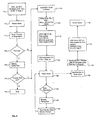
- step 110 of the operation of programmed microprocessor 66 (FIG. 2), transistor Q1 is held OFF (under direction of GPIO 76 of ASIC 62) upon power on/reset ("POR") of grab printer 58.
- POR power on/reset
- resistor R1 (see FIG. 2), tied at one end to ground, holds ENABLE line input 90 in a logic low state, which forces all the parallel port I/O lines 92 of VCU 56 into a HIGH Z state, leaving access and control of port 60 to printer unit ASIC 62.
- the parallel port I/O lines to printer unit 58 not being in a HIGH Z state, are enabled to communicate through port 60, thus placing grab printer 58 in print mode, and making it capable of carrying out full (ink jet) printer operation, as depicted by step 112.
- a transition from print mode to video mode is accomplished by entry of the imaging system into a preview mode or snap mode (step 114), for example, at user direction.
- Preview mode may be initiated when video capture software 100 is activated on computer 52. In this mode, captured video frames, obtained through VCU 56 (which have been stored), may be viewed on the video display monitor (not shown) of computer 52 (step 114A, following the non-print preview mode sequence). Illustrative of computer capabilities, the frame may be viewed at a rate of two frames every second.
- Snap mode is similar to preview mode in all respects except that in this mode, a single image is captured and sent to computer 52.
- Preview or snap mode use of video frame data indicates the computer user's concern with video frame imaging capabilities, and thus is relied upon to prompt video capture software 100 to generate a multi-byte "escape sequence" of control signals for transmission by port I/O driver software 98 through ports 96 and 60 to ASIC 62 (steps 116).
- the escape sequence signals are received as data by ASIC 62 through port data input logic block 78.
- the escape sequence employed in a preferred embodiment is coded as ESC* M O 4 in ASCII, and "1B-2A-6D-00-34" in hexadecimal.)
- the video capture software brings IEEE-1284 line to a HIGH logic state (step 116A).
- ASIC 62 drives signal lines of port output logic 80 (reserved for output of control signals to printer 52) to a HIGH Z state, and turns ON transistor Q1 using GPIO 76 (step 118). Turning on transistor Q1 electrically connects DATA LINE 3 84 of the IEEE-1284 port bus 88 to ENABLE line 90.
- DATA LINE 3 84 is driven HIGH by video capture software 100, video capture control chip 86 is enabled and frees lines 92 from a HIGH Z state, and the video capture control chip 86 negotiates an IEEE-1284 reverse channel to enable transmission of video data over port lines 92, through parallel port 60.
- signal lines of port output logic sub-block 80 are forced into HIGH Z state (i.e., disabled) in step 118, signal lines of port data sub-block 78 and port input logic sub-block 82 are not forced into HIGH Z state in response to the receipt by ASIC 62 of escape sequence signals. Accordingly, while VCU 56 is enabled, although ASIC 62 of printer unit 58 cannot send control signals necessary to gain access of port 60, ASIC 62 can and does continue to monitor and to parse/interpret port input logic signals (received through sub-block 74) and port data signals (received through sub-block 78).
- ASIC 74 continues to monitor and parse/interpret all control and data information appearing in standard IEEE-1284 format passing from port 60, including control signals intended for ASIC 62. This monitoring and parsing/interpreting activity permits ASIC 62 to determine when a mode change is being indicated (as described below), and allows ASIC 62 to re-enable signal lines of port output logic sub-block 80 for (re)capturing port 60, when appropriate.
- Such a channel may be, for example, a "reverse channel” of the type provided when operating under a protocol that complies with IEEE-1284 formats. Data sent to computer 52 over such a channel may conform to IEEE-1284 (four-bit) nibble mode transmission.
- imaging system 50 transitions to video mode (step 122). Transition to video mode results in director software 106 determining (from interfacing with driver software 98) that VCU 56 has access of port 60 and not allowing printer driver software to access port I/O driver software 98 until a subsequent mode change.
- video capture software 100 can request VCU 56 to capture and save in memory of computer 14 (not shown) a frame of video data. That data will have been captured and digitized (by A/D converter 95) and stored (memory 94) in digitized form by VCU 56 en route to computer 52.
- frame imaging system 50 While in video mode, frame imaging system 50, among other things, awaits a print request (step 124).
- printer driver software 104 any print request, occurring while system 50 is operating in a Windows operating system environment and in video mode, are handled by printer driver software 104.
- Printer driver software 104 will be notified by director software 106, or checks I/O driver software 98 status directly, that port 60 is available to VCU 56 and not to printer unit 58. This notice is provided by director software 106 when a print request is received from software 104 by polling port I/O driver software 98 to verify that video frame data is being received (or is receivable) from VCU 56 and that driver software 104 may not yet pass on print image data from print driver software 104.
- software 104 may check I/O driver software 98 status directly.
- I/O driver software 98 is in video mode causes printer driver software 104 to display on the video monitor (not shown) of computer 52 a dialog box (step 126) which states that port 60 is in use and not available (step 128).
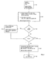
- the user To print, the user must exit preview or snap mode (step 130), which mode prompted and resulted in the enablement of video mode operation (step 114).
- preview mode or snap mode exit step 130 can be achieved based on a direct prompt for such a step as permitted by video capture software 100.
- Preview or snap mode exit involves execution of a simplified termination phase sequence by video capture software 100.
- this sequence may be executed in compliance with IEEE-1284 standards.
- Termination phase sequence signals are transmitted under direction of software 100 and port I/O driver software 98, which have not yet granted printer driver software 104 the opportunity to transfer print image data.
- the termination sequence brings IEEE-1284 control line LOW _SELECTIN, which is connected via the IEEE-1284 bus 88 to port input logic sub-block 82 being monitored by ASIC 62.
- software 100 releases DATA LINE 3 84 for normal forward data transfer (step 132).
- ASIC 62 interprets LOW _SELECTIN as a direction to turn OFF Q1 using GPIO 76, forcing enable line 90 into a LOW logic state, which disables VCU 56, putting all VCU port I/O lines, lines 92, in a HIGH Z state (step 134).
- ASIC 62 negotiates to obtain an IEEE forward channel over which print data would be forwarded by computer 52 to printer unit 58 through data lines of port data sub-block 78.
- video software 100 will detect any attempt to initiate printing (step 138). The absence of any such attempt allows software 100 to send the escape sequence and enter video mode.
- an attempt to initiate preview or snap mode in software 100 when a print job is in progress will result in the user of the computer 52 having the opportunity to respond to a dialog box displayed by software 100 (step 140), providing the option to cancel the print job or hold it in abeyance until print mode has been (re)established (step 142, 144).
- Cancellation of the print job by the user enables sending the escape sequence (step 116) and all that follows to enter video mode. A decision by the user not to cancel the print job results in a wait for the user until the print job is completed.
- Video mode can be re-established by entering preview mode (114) and progressing through steps 116, 116A, 118 and 120. Preferably, whenever preview mode is exited (130), steps 132 and 134 will be executed to reestablish print mode.
- steps 132 and 134 will be executed to reestablish print mode.
- the foregoing description of the steps of operating system 50 is illustrative and not limiting. Modifications not inconsistent with the present invention may be made. For example, the use of dialogue boxes (steps 140 and 142, and 126 and 128) is not required.
- Director software 106 can be written to ensure that the user exits preview or snap mode to complete print jobs whenever a print job request is interposed, instead of inserting these lines of code in driver software 104 and video software 100.
- the present invention allows for an elegant, coordinated transition between use of the VCU of the imaging system and the printer of the imaging system.
- quick real-time coordinated arbitration of the use of port 60 in the manner described also opens the door for ready use of video frame data to create print images under control of the resident software of computer 52.
- FIG. 4 use of video frame data captured by VCU 56 to create print images is illustratively described.
- the text in parentheses in the boxes of Fig. 4 indicates which software or hardware is performing the referenced task shown in the box.
- VCU 56 When a frame of video data is captured by VCU 56 (step 150), it is converted, for example, to 640 x 480 pel or 1500 x 1125 pel by 24 bit RGB (Red/Green/Blue) color data using video capture software 100, and stored in common graphic file formats using video capture software 100 for further processing (step 152) if further processing is selected by the user when the choice becomes selectable (step 154).
- Video capture software 100 or graphic application software 102 can scale an image captured by the file of video data to any preferred allowed dimension if the user so desires (step 156). An image, whether scaled or not, may then be chosen for printing by the user (step 158).
- Printing a video frame in, for example, the Windows environment with (Windows) printer driver software 104 involves conversion of the 640 x 480 pel or 1500 x 1125 pel by 24 bit color data in the file into, for example, 1 bit x 600 x 600 dots per inch CMY (Cyan/Magenta/Yellow) print data (step 160) that can be printed by a color ink jet printer implementation of printer unit 58 of grab printer 54 (step 162).
- the color format is CMY as an example but may be other color formats such as CMY + K (Cyan/Magenta/Yellow/Black or hexcolor formats like CMY + Kcm (Cyan/Magenta/Yellow/Black dilute Cyan, Dilute Magenta).
- FIG. 5 shows a system 180 in which like parts to system 50 are similarly numbered and labelled.
- system 180 further include universal serial bus ("USB") control circuit 170, a USB input port 172, and a USB transfer port 174.
- USB universal serial bus
- An enhanced VCU 176 is part of a grab printer 178 of imaging system 180, which system also includes a computer 182.
- Grab printer 178 further includes a printer unit 184, which (like printer unit 58) includes microprocessor 66, memory 68, ASIC 62, and motor and print element driver circuits 70.
- computer 182 housed in its own cabinet separate from grab printer 178, is an enhanced version of computer 52 and includes USB components. Specifically, computer 182 includes a USB transfer port 186, USB port I/O driver software 188, and USB device application software 190.
- USB components in computer 182 and VCU 176 of system 180 permits the system to provide high speed serial interface capability through grab printer 178 to computer 182 for USB-capable peripheral imaging devices.
- such capability makes possible the use of grab printer 178 with a "daisy chain" of USB-capable peripheral devices attached to each other for serial data transfer along the chain even from a peripheral-most device forward through to the device directly connected to port 172 of VCU 176.
- USB capability is important because, while many imaging devices provide composite video frame data outputs, some devices do not have such capability. For example, most image scanner and some digital cameras presently being made available in the marketplace provide USB (digital) outputs rather than composite (analog) video frame data outputs. In any event, providing both USB and composite video data capability in the computer and grab printer (VCU) of the imaging system creates an essentially universal imaging capability.
- USB-capable device e.g., a scanner
- computer 182 Upon activation of USB device application software 190, computer 182 becomes operative to upload image data from the USB-capable device. More specifically, under control of software 190, the stored data is communicated through USB control chip 170, which controls the transfer of the already digitized video data through ports 174 and 186 for delivery to USB port I/O driver software 188, which prepares the data for storage and further processing by application software 190. The stored data then can be viewed on the display monitor (not shown) of computer 182.
- the video data can be formatted as a print file and sent to printer driver software 104 and printed via port 96 operating in print mode.
- the video data could be sent from application software 190 to installed graphic application software 102 for other processing and then printed or viewed using the display monitor of computer 182.
- printer unit 184 does not use the USB components to facilitate printing. Those components are used solely to allow convenient transfer of data from USB-capable imaging devices at the prompting of USB device application software 190. Even printing of USB video data is handled via parallel port 96 according to the port arbitration scheme described above for system 50. Accordingly, it should be observed that printing images of USB device origin will not be unduly impeded by the presence and use of the composite video data capabilities of VCU 176. Plainly, coordinated use of USB frame capture capabilities is unimpeded since USB video data transfer is through dedicated ports 174 and 186.
- the present invention provides a convenient, one-stop imaging system with coordinate functionality in capturing, processing and printing video frame data.
- the present invention also comprises a method incorporating the foregoing teachings.
- This method is directed to a method for video frame imaging and printing with a grab printer having an integrated video capture unit, a printer unit and a grab printer port connector operatively connected to the video capture unit and the printer unit, and an arbitration control circuit.
- the method comprises the steps of: creating video frame data from a video input; providing control of the grab printer port connector to the video capture unit to make video frame data transferable between the integrated video capture unit and the grab printer port connector during a first mode of operation, and providing control of the grab printer port connector to the printer unit to make print image data transferable to the grab printer parallel port connector from a print image data input and between the grab printer port connector and the printer unit during a second mode of operation.
Claims (20)
- Drucker (54) zur Erzeugung von Videorahmendaten und zum Drucken von Bildern, die Druckbilddaten entsprechen, umfassend:eine Druckereinheit (58) zum Drucken von Bildern, die Druckbilddaten entsprechen; gekennzeichnet durch Umfasseneiner integrierten Video-Capture-Einheit (56), um Videorahmendaten von einem Videoeingang (42) zu erzeugen; undeines ersten Druckerportverbinders (60), der mit der integrierten Video-Capture-Einheit (56) und der Druckereinheit (58) in Wirkverbindung gekoppelt ist.
- Drucker nach Anspruch 1, bei dem der Videoeingang (42) ein FBAS-Eingangsport ist und der erste Druckerportverbinder (60) ein Parallelportverbinder ist.
- Drucker nach einem vorangehenden Anspruch, weiter umfassend:einen USB-Eingangsport (192);einen USB-Portverbinder (174);eine USB-Steuerschaltung (170), die zwischen dem USB-Eingangsport (192) und dem USB-Portverbinder (174) gekoppelt ist.
- Drucker nach einem vorangehenden Anspruch, bei dem die Druckereinheit umfasst:eine Druckelementtreiberschaltung (70); undeine Druckersteuerlogikschaltung (72), die zwischen der Druckelementtreiberschaltung (70) und dem ersten Druckerportverbinder (60) gekoppelt ist.
- Drucker nach Anspruch 4, der eine Auswahlschaltung (64) umfasst, die mit der Video-Capture-Einheit (56) und der Druckereinheit (58) in Wirkverbindung gekoppelt ist.
- Drucker nach Anspruch 5, bei dem die Auswahlschaltung (64) einen Schalter (Q1) umfasst, der aufweist: einen Steuereingang, der gekoppelt ist, um ein Steuersignal von der Druckersteuerschaltung (72) zu empfangen, und einen Ausgang, der gekoppelt ist, um den ersten Druckerportverbinder (60) mit der Video-Capture-Einheit selektiv zu verbinden.
- Drucker nach Anspruch 6, der eine Porteingangslogikschaltung (82) umfasst, die zwischen mindestens einer Datenleitung (88) und der Druckerlogikschaltung (72) gekoppelt ist, um zu ermöglichen, dass die Druckerlogikschaltung (72) den Zustand der mindestens einen Leitung (88) erfasst.
- Drucker nach einem der Ansprüche 1 bis 4, der eine Einrichtung zur selektiven Aktivierung einer oder der anderen der Video-Capture-Einheit (56) und der Druckereinheit (58) umfasst.
- Drucker nach einem der Ansprüche 1 bis 4, weiter umfassend:eine Auswahlschaltung (64),wobei die Auswahlschaltung (64) in einem ersten Betriebszustand eine Übertragung von Videorahmendaten zwischen dem ersten Druckerportverbinder (60) und der integrierten Video-Capture-Einheit (56) ermöglicht; und
wobei die Auswahlschaltung (64) in einem zweiten Betriebszustand eine Übertragung von Druckbilddaten zwischen dem ersten Druckerportverbinder (60) und der Druckereinheit (58) ermöglicht. - Drucker nach einem der Ansprüche 1 bis 3, wobei der Drucker Bilddaten empfangen und erzeugen kann und
die integrierte Video-Capture-Einheit (56) Bilddaten in universaler serieller Form empfangen kann, und der weiter umfasst:eine Auswahlschaltung (64); undeinen zweiten Druckerportverbinder (174), der mit der integrierten Video-Capture-Einheit (56) in Wirkverbindung gekoppelt ist,wobei der erste Druckerportverbinder (60) auf die Auswahlschaltung (64) anspricht, um Videorahmendaten zwischen dem ersten Druckerportverbinder (60) und der integrierten Video-Capture-Einheit (56) während eines ersten Modus eines Betriebs übertragbar zu machen,
wobei der erste Druckerportverbinder (60) auf die Auswahlschaltung (64) anspricht, um Druckbilddaten zwischen dem ersten Druckerportverbinder (60) und der Druckereinheit während eines zweiten Modus eines Betriebs übertragbar zu machen, und
wobei die Bilddaten in universaler serieller Form zwischen der integrierten Video-Capture-Einheit (56) und dem zweiten Druckerportverbinder (174) übertragbar sind. - Drucker nach Anspruch 9 oder 10, bei dem die Druckereinheit (58) auf Portdaten anspricht, die empfangen werden, wenn sich die Auswahlschaltung (64) in dem ersten Betriebszustand befindet, um die Auswahlschaltung (64) in den zweiten Betriebszustand zu setzen.
- Abbildungssystem zur Verarbeitung von Bilddaten, die Videorahmendaten umfassen, und zum Drucken von Bildern, die Druckbilddaten entsprechen, umfassend die Kombination von:einem Drucker (54), wie durch einen der Ansprüche 1 bis 3 bereitgestellt; undeinem Computer (52), umfassend:einen ersten Computerportverbinder (96), der mit dem ersten Druckerportverbinder (60) des Druckers (54) gekoppelt ist.
- System nach Anspruch 12, bei dem der Computer (52) weiter umfasst:Druckertreibersoftware (104);Video-Capture-Software (100); undDirectorsoftware (106) zur Arbitrierung einer Verbindung von Daten zwischen dem ersten Parallelportverbinder (96) und der Druckertreibersoftware (104) und dem ersten Parallelportverbinder (96) und der Video-Capture-Software (100).
- Abbildungssystem nach Anspruch 12, bei dem
der Computer (52) eine Einrichtung zum Empfangen und Verarbeiten von Videorahmendaten und zur Erzeugung von Druckbilddaten umfasst, das weiter umfasst:eine Auswahlschaltung (64); undwobei der erste Computerportverbinder (96) und der erste Druckerportverbinder (60) gekoppelt sind, um durch die Video-Capture-Einheit (56) erzeugte Videorahmendaten zwischen der Video-Capture-Einheit (56) und dem Computer (52) zur Verarbeitung durch den Computer (52) zu übertragen, wenn sich die Auswahlschaltung (64) in einem ersten Betriebszustand befindet; und
wobei der erste Computerportverbinder (96) und der erste Druckerportverbinder (60) gekoppelt sind, um Druckbilddaten zwischen dem Computer (52) und der Druckereinheit (58) zu übertragen, um Bilder unter Verwendung der Druckereinheit (58) zu drucken, wenn sich die Auswahlschaltung (64) in einem zweiten Betriebszustand befindet. - Abbildungssystem nach Anspruch 12, bei dem
der Computer (52) eine Einrichtung zum Empfangen und Verarbeiten von Videorahmendaten und einen zweiten Computerportverbinder (186) umfasst, das weiter umfasst;
eine Auswahlschaltung (64); und wobei
der Drucker (54) Bilddaten in USB-Form empfangen kann und weiter einen zweiten Druckerportverbinder (174) umfasst,
wobei der erste Computerportverbinder (96) und der erste Druckerportverbinder (60) miteinander gekoppelt sind, um durch die Video-Capture-Einheit (56) erzeugte Videorahmendaten zwischen der Video-Capture-Einheit (56) und dem Computer (52) zur Verarbeitung durch den Computer (52) zu übertragen, wenn sich die Auswahlschaltung (64) in einem ersten Betriebszustand befindet;
wobei der erste Computerportverbinder (96) und der erste Druckerportverbinder (60) gekoppelt sind, um Druckbilddaten zwischen dem Computer (52) und der Druckereinheit (158) zu übertragen, um Bilder unter Verwendung der Druckereinheit (58) zu drucken, wenn sich die Auswahlschaltung (64) in einem zweiten Betriebszustand befindet; und
wobei der zweite Computerportverbinder (186) und der zweite Druckerportverbinder (174) miteinander gekoppelt sind, um Bilddaten in USB-Form zwischen der integrierten Video-Capture-Einheit (56) und dem Computer (52) zur Verarbeitung durch den Computer (52) zu übertragen. - Abbildungssystem nach Anspruch 14 oder 15, bei dem der Drucker (54) auf Portdaten von dem Computer (52) anspricht, die empfangen werden, wenn sich die Auswahlschaltung (64) im ersten Betriebszustand befindet, um die Auswahlschaltung (64) in den zweiten Betriebszustand zu setzen.
- Verfahren zum Abbilden, einschließlich zum Videorahmenabbilden, und Drucken unter Verwendung eines Greiferdruckers (54), der aufweist: eine integrierte Video-Capture-Einheit (56), eine Druckereinheit (58) und einen erster Greiferdruckerportverbinder (60), der mit der Video-Capture-Einheit (56) und der Druckereinheit (158) in Wirkverbindung gekoppelt ist, und eine Arbitrierungssteuerschaltung (64), gekennzeichnet durch Umfassen der Schritte:Erzeugung von Videorahmendaten von einem Videoeingang (42);Bereitstellen einer Steuerung des ersten Greiferdruckerportverbinders (60) an der Video-Capture-Einheit (56), um Videorahmendaten zwischen der integrierten Video-Capture-Einheit (56) und dem ersten Greiferdruckerportverbinder (60) während eines ersten Modus eines Betriebs übertragbar zu machen; undBereitstellen einer Steuerung des ersten Greiferdruckerportverbinders (60) an der Druckereinheit (58), um Druckbilddaten von einem Druckbilddateneingang zum ersten Greiferdruckerportverbinder (60) und zwischen dem ersten Greiferdruckerportverbinder (60) und der Druckereinheit (158) während eines zweiten Modus eines Betriebs übertragbar zu machen.
- Verfahren nach Anspruch 17, bei dem der Greiferdrucker (54) weiter einen zweiten Greiferdruckerportverbinder (174) umfasst, und welches weiter den Schritt umfasst:Übertragen von Daten in universaler serieller Form zwischen der integrierten Video-Capture-Einheit (56) und dem zweiten Greiferdruckerportverbinder (174).
- Verfahren nach Anspruch 17 oder 18, bei dem der Schritt eines Erzeugens von Videorahmendaten von einem Videoeingang (42) umfasst: Erzeugen der Videorahmendaten von einem FBAS-Dateneingang (42).
- Verfahren nach Anspruch 17, 18 oder 19, weiter umfassend den Schritt: Bereitstellen von Videorahmendaten an der Druckereinheit (58) während des ersten Modus eines Betriebs, um die Druckereinheit (58) zu aktivieren, um eine Steuerung des ersten Greiferdruckerportverbinders (60) während des zweiten Modus eines Betriebs zu erhalten.
Applications Claiming Priority (2)
| Application Number | Priority Date | Filing Date | Title |
|---|---|---|---|
| US950547 | 1997-10-15 | ||
| US08/950,547 US5970220A (en) | 1997-10-15 | 1997-10-15 | Printer having universal image port and related system and method |
Publications (3)
| Publication Number | Publication Date |
|---|---|
| EP0910203A2 EP0910203A2 (de) | 1999-04-21 |
| EP0910203A3 EP0910203A3 (de) | 2000-04-26 |
| EP0910203B1 true EP0910203B1 (de) | 2007-03-07 |
Family
ID=25490577
Family Applications (1)
| Application Number | Title | Priority Date | Filing Date |
|---|---|---|---|
| EP98308416A Expired - Lifetime EP0910203B1 (de) | 1997-10-15 | 1998-10-15 | Drucker mit universellem Bildport sowie System und Verfahren dafür |
Country Status (4)
| Country | Link |
|---|---|
| US (1) | US5970220A (de) |
| EP (1) | EP0910203B1 (de) |
| JP (1) | JPH11265265A (de) |
| DE (1) | DE69837240T2 (de) |
Families Citing this family (25)
| Publication number | Priority date | Publication date | Assignee | Title |
|---|---|---|---|---|
| US6040792A (en) * | 1997-11-19 | 2000-03-21 | In-System Design, Inc. | Universal serial bus to parallel bus signal converter and method of conversion |
| US6259532B1 (en) * | 1998-04-08 | 2001-07-10 | Intel Corporation | Method and apparatus for communicating with a plurality of peripheral devices through a single parallel port |
| TW456543U (en) * | 1998-05-18 | 2001-09-21 | Mustek Systems Inc | Scanner using the universal serial bus as a transmission interface |
| US6064492A (en) * | 1998-05-29 | 2000-05-16 | Xerox Corporation | Image data interface between digital front end and printer |
| US6131135A (en) * | 1998-06-30 | 2000-10-10 | Intel Corporation | Arbitration method for a system with two USB host controllers |
| US6233389B1 (en) | 1998-07-30 | 2001-05-15 | Tivo, Inc. | Multimedia time warping system |
| US7558472B2 (en) | 2000-08-22 | 2009-07-07 | Tivo Inc. | Multimedia signal processing system |
| US6198511B1 (en) * | 1998-09-10 | 2001-03-06 | Intel Corporation | Identifying patterns in closed caption script |
| US7143150B1 (en) * | 1999-12-09 | 2006-11-28 | Ricoh Company, Ltd. | Method of configuring a computer to include the available options of a printer |
| US6859832B1 (en) | 2000-10-16 | 2005-02-22 | Electronics For Imaging, Inc. | Methods and systems for the provision of remote printing services over a network |
| US7574545B2 (en) | 2000-10-16 | 2009-08-11 | Electronics For Imaging, Inc. | Method and apparatus for controlling a document output device with a control request stored at a server |
| US7095518B1 (en) | 2000-10-16 | 2006-08-22 | Electronics For Imaging, Inc. | Spooling server apparatus and methods for receiving, storing, and forwarding a print job over a network |
| US7587468B2 (en) | 2000-10-16 | 2009-09-08 | Electronics For Imaging, Inc. | Methods and systems for the provision of printing services |
| US6978299B1 (en) * | 2000-10-16 | 2005-12-20 | Electronics For Imaging, Inc. | Print driver apparatus and methods for forwarding a print job over a network |
| US6748471B1 (en) | 2000-10-16 | 2004-06-08 | Electronics For Imaging, Inc. | Methods and apparatus for requesting and receiving a print job via a printer polling device associated with a printer |
| US20020135808A1 (en) * | 2001-03-22 | 2002-09-26 | Parry Travis J. | Method and apparatus for printing video data |
| US20040252340A1 (en) * | 2001-10-03 | 2004-12-16 | Seiko Epson Corporation | Image processing system, image processing method, template producing system and template data structure |
| JP4059027B2 (ja) * | 2001-10-03 | 2008-03-12 | セイコーエプソン株式会社 | プリンタおよびプリンタの印刷条件設定方法 |
| US7528974B2 (en) | 2003-02-28 | 2009-05-05 | Electronics For Imaging, Inc. | Methods and apparatus for providing universal print services and asynchronous message services |
| US20050108032A1 (en) * | 2003-11-17 | 2005-05-19 | Josephsen Mark M. | Method and apparatus to account for hard copy cost |
| US20060256378A1 (en) * | 2004-06-09 | 2006-11-16 | Roland Korst | Apparatus and method for controlling and managing and RFID printer |
| US20050275880A1 (en) * | 2004-06-09 | 2005-12-15 | Roland Korst | Apparatus and method for controlling and managing an RFID printer system |
| US7520437B2 (en) * | 2005-06-21 | 2009-04-21 | Lexmark International, Inc. | USB host device for printer interface |
| KR100739752B1 (ko) * | 2005-11-04 | 2007-07-13 | 삼성전자주식회사 | 화상형성장치 및 방법 |
| CN103383676B (zh) | 2012-07-13 | 2016-07-20 | 威盛电子股份有限公司 | 集线器装置以及用以初始化集线器装置的方法 |
Family Cites Families (12)
| Publication number | Priority date | Publication date | Assignee | Title |
|---|---|---|---|---|
| US4680626A (en) * | 1985-04-09 | 1987-07-14 | Benson, Inc. | Color image processing system for converting analog video-to-digital data |
| CA1288516C (en) * | 1987-07-31 | 1991-09-03 | Leendert M. Bijnagte | Apparatus and method for communicating textual and image information between a host computer and a remote display terminal |
| US5150456A (en) * | 1990-08-06 | 1992-09-22 | Elite High Technology, Inc. | Graphic image printing system and method |
| WO1993009501A1 (en) * | 1991-11-01 | 1993-05-13 | Yeh Keming W | Portable device having data storage capability for transferring data between a portable computer and a desktop computer |
| US5438438A (en) * | 1992-05-29 | 1995-08-01 | Goldstar Co., Ltd. | Apparatus for synthesizing videos |
| US5341174A (en) * | 1992-08-17 | 1994-08-23 | Wright State University | Motion compensated resolution conversion system |
| US5758037A (en) * | 1994-10-25 | 1998-05-26 | Hewlett-Packard Company | Print controller with simplified video data processing |
| JPH08163363A (ja) * | 1994-12-12 | 1996-06-21 | Fuji Xerox Co Ltd | 画像形成装置 |
| WO1996032265A1 (en) * | 1995-04-12 | 1996-10-17 | Eastman Kodak Company | A color video printer and a photocd system with integrated printer |
| US5859652A (en) * | 1995-04-12 | 1999-01-12 | Eastman Kodak Company | Color video printer and a photo CD system with integrated printer |
| US5736997A (en) * | 1996-04-29 | 1998-04-07 | Lexmark International, Inc. | Thermal ink jet printhead driver overcurrent protection scheme |
| US5784581A (en) * | 1996-05-03 | 1998-07-21 | Intel Corporation | Apparatus and method for operating a peripheral device as either a master device or a slave device |
-
1997
- 1997-10-15 US US08/950,547 patent/US5970220A/en not_active Expired - Lifetime
-
1998
- 1998-10-15 JP JP33012398A patent/JPH11265265A/ja active Pending
- 1998-10-15 DE DE69837240T patent/DE69837240T2/de not_active Expired - Fee Related
- 1998-10-15 EP EP98308416A patent/EP0910203B1/de not_active Expired - Lifetime
Also Published As
| Publication number | Publication date |
|---|---|
| EP0910203A2 (de) | 1999-04-21 |
| US5970220A (en) | 1999-10-19 |
| JPH11265265A (ja) | 1999-09-28 |
| DE69837240D1 (de) | 2007-04-19 |
| EP0910203A3 (de) | 2000-04-26 |
| DE69837240T2 (de) | 2007-11-08 |
Similar Documents
| Publication | Publication Date | Title |
|---|---|---|
| EP0910203B1 (de) | Drucker mit universellem Bildport sowie System und Verfahren dafür | |
| US7113218B2 (en) | Digital docking system user interface method and apparatus | |
| US6104886A (en) | Print system and electronic camera | |
| US6711637B2 (en) | Communication apparatus, image processing apparatus, communication system, communication method, image processing method and storage medium | |
| JP4089106B2 (ja) | 投射表示装置、投射表示システム | |
| US8713206B2 (en) | Display apparatus, control method thereof, and program | |
| JP5816003B2 (ja) | 画像処理装置、画像処理装置の制御方法およびプログラム | |
| JPH10285322A (ja) | 画像処理装置及び画像処理システム | |
| US6711626B1 (en) | Composite device, composite device system, method of controlling composite device, and medium on which program for controlling composite device is recorded | |
| US20040189808A1 (en) | Host/function apparatus | |
| US20090121968A1 (en) | Electronic Device | |
| KR20040010198A (ko) | 화상기억장치, 외부화상처리장치, 화상기억장치를 위한제어방법 및 외부화상처리장치를 위한 제어방법 | |
| JP3625345B2 (ja) | 画像処理システム | |
| US20050024497A1 (en) | Image supply device, communication apparatus, recording system and control method thereof | |
| JP2004194244A (ja) | 印刷データを生成することができるディジタルカメラ | |
| JPH10215427A (ja) | デジタルカラープリンタ、デジタルカメラ及びこれらを用いたデジタルカラープリントシステム | |
| US20070103709A1 (en) | Data processing apparatus, and method for controlling the same | |
| US20060132827A1 (en) | Methods and systems for providing external processing for a printing device | |
| JP4615646B2 (ja) | プリンタ | |
| JP3613502B2 (ja) | 画像形成システム及びその周辺機器 | |
| JP3957203B2 (ja) | 周辺機器管理装置 | |
| EP0484145B1 (de) | Ferndrucker mit Fax | |
| KR200180210Y1 (ko) | 팩시밀리와 퍼스널 컴퓨터 복합기기 | |
| JP4348916B2 (ja) | 画像出力システムおよびこれに用いる画像出力装置並びに制御方法 | |
| JP2005049926A (ja) | デバイス機器 |
Legal Events
| Date | Code | Title | Description |
|---|---|---|---|
| PUAI | Public reference made under article 153(3) epc to a published international application that has entered the european phase |
Free format text: ORIGINAL CODE: 0009012 |
|
| AK | Designated contracting states |
Kind code of ref document: A2 Designated state(s): DE FR GB |
|
| AX | Request for extension of the european patent |
Free format text: AL;LT;LV;MK;RO;SI |
|
| PUAL | Search report despatched |
Free format text: ORIGINAL CODE: 0009013 |
|
| AK | Designated contracting states |
Kind code of ref document: A3 Designated state(s): AT BE CH CY DE DK ES FI FR GB GR IE IT LI LU MC NL PT SE |
|
| AX | Request for extension of the european patent |
Free format text: AL;LT;LV;MK;RO;SI |
|
| 17P | Request for examination filed |
Effective date: 20001016 |
|
| AKX | Designation fees paid |
Free format text: DE FR GB |
|
| 17Q | First examination report despatched |
Effective date: 20031120 |
|
| GRAP | Despatch of communication of intention to grant a patent |
Free format text: ORIGINAL CODE: EPIDOSNIGR1 |
|
| GRAS | Grant fee paid |
Free format text: ORIGINAL CODE: EPIDOSNIGR3 |
|
| GRAA | (expected) grant |
Free format text: ORIGINAL CODE: 0009210 |
|
| AK | Designated contracting states |
Kind code of ref document: B1 Designated state(s): DE FR GB |
|
| REG | Reference to a national code |
Ref country code: GB Ref legal event code: FG4D |
|
| REF | Corresponds to: |
Ref document number: 69837240 Country of ref document: DE Date of ref document: 20070419 Kind code of ref document: P |
|
| ET | Fr: translation filed | ||
| PLBE | No opposition filed within time limit |
Free format text: ORIGINAL CODE: 0009261 |
|
| STAA | Information on the status of an ep patent application or granted ep patent |
Free format text: STATUS: NO OPPOSITION FILED WITHIN TIME LIMIT |
|
| 26N | No opposition filed |
Effective date: 20071210 |
|
| PGFP | Annual fee paid to national office [announced via postgrant information from national office to epo] |
Ref country code: DE Payment date: 20080430 Year of fee payment: 10 |
|
| PGFP | Annual fee paid to national office [announced via postgrant information from national office to epo] |
Ref country code: GB Payment date: 20080415 Year of fee payment: 10 |
|
| PG25 | Lapsed in a contracting state [announced via postgrant information from national office to epo] |
Ref country code: FR Free format text: LAPSE BECAUSE OF NON-PAYMENT OF DUE FEES Effective date: 20071031 |
|
| GBPC | Gb: european patent ceased through non-payment of renewal fee |
Effective date: 20081015 |
|
| REG | Reference to a national code |
Ref country code: FR Ref legal event code: ST Effective date: 20090630 |
|
| PG25 | Lapsed in a contracting state [announced via postgrant information from national office to epo] |
Ref country code: DE Free format text: LAPSE BECAUSE OF NON-PAYMENT OF DUE FEES Effective date: 20090501 |
|
| PG25 | Lapsed in a contracting state [announced via postgrant information from national office to epo] |
Ref country code: GB Free format text: LAPSE BECAUSE OF NON-PAYMENT OF DUE FEES Effective date: 20081015 |
|
| PGFP | Annual fee paid to national office [announced via postgrant information from national office to epo] |
Ref country code: FR Payment date: 20080422 Year of fee payment: 10 |
|
| PG25 | Lapsed in a contracting state [announced via postgrant information from national office to epo] |
Ref country code: FR Free format text: LAPSE BECAUSE OF NON-PAYMENT OF DUE FEES Effective date: 20081031 |