EP0909924A2 - Suspension d'une chambre de combustion annulaire de turbine à gaz - Google Patents
Suspension d'une chambre de combustion annulaire de turbine à gaz Download PDFInfo
- Publication number
- EP0909924A2 EP0909924A2 EP98117869A EP98117869A EP0909924A2 EP 0909924 A2 EP0909924 A2 EP 0909924A2 EP 98117869 A EP98117869 A EP 98117869A EP 98117869 A EP98117869 A EP 98117869A EP 0909924 A2 EP0909924 A2 EP 0909924A2
- Authority
- EP
- European Patent Office
- Prior art keywords
- combustion chamber
- gas turbine
- suspension
- annular gas
- circumference
- Prior art date
- Legal status (The legal status is an assumption and is not a legal conclusion. Google has not performed a legal analysis and makes no representation as to the accuracy of the status listed.)
- Granted
Links
- 239000000725 suspension Substances 0.000 title claims abstract description 19
- 238000002485 combustion reaction Methods 0.000 claims abstract description 62
- 238000001816 cooling Methods 0.000 description 4
- 230000001154 acute effect Effects 0.000 description 3
- 230000000737 periodic effect Effects 0.000 description 3
- 238000010276 construction Methods 0.000 description 2
- 230000015556 catabolic process Effects 0.000 description 1
- 239000000446 fuel Substances 0.000 description 1
- 238000002347 injection Methods 0.000 description 1
- 239000007924 injection Substances 0.000 description 1
- 230000003252 repetitive effect Effects 0.000 description 1
- 239000000243 solution Substances 0.000 description 1
Images
Classifications
-
- F—MECHANICAL ENGINEERING; LIGHTING; HEATING; WEAPONS; BLASTING
- F23—COMBUSTION APPARATUS; COMBUSTION PROCESSES
- F23R—GENERATING COMBUSTION PRODUCTS OF HIGH PRESSURE OR HIGH VELOCITY, e.g. GAS-TURBINE COMBUSTION CHAMBERS
- F23R3/00—Continuous combustion chambers using liquid or gaseous fuel
- F23R3/42—Continuous combustion chambers using liquid or gaseous fuel characterised by the arrangement or form of the flame tubes or combustion chambers
- F23R3/60—Support structures; Attaching or mounting means
-
- F—MECHANICAL ENGINEERING; LIGHTING; HEATING; WEAPONS; BLASTING
- F01—MACHINES OR ENGINES IN GENERAL; ENGINE PLANTS IN GENERAL; STEAM ENGINES
- F01D—NON-POSITIVE DISPLACEMENT MACHINES OR ENGINES, e.g. STEAM TURBINES
- F01D25/00—Component parts, details, or accessories, not provided for in, or of interest apart from, other groups
- F01D25/16—Arrangement of bearings; Supporting or mounting bearings in casings
- F01D25/162—Bearing supports
- F01D25/164—Flexible supports; Vibration damping means associated with the bearing
-
- F—MECHANICAL ENGINEERING; LIGHTING; HEATING; WEAPONS; BLASTING
- F05—INDEXING SCHEMES RELATING TO ENGINES OR PUMPS IN VARIOUS SUBCLASSES OF CLASSES F01-F04
- F05B—INDEXING SCHEME RELATING TO WIND, SPRING, WEIGHT, INERTIA OR LIKE MOTORS, TO MACHINES OR ENGINES FOR LIQUIDS COVERED BY SUBCLASSES F03B, F03D AND F03G
- F05B2230/00—Manufacture
- F05B2230/60—Assembly methods
- F05B2230/604—Assembly methods using positioning or alignment devices for aligning or centering, e.g. pins
- F05B2230/606—Assembly methods using positioning or alignment devices for aligning or centering, e.g. pins using maintaining alignment while permitting differential dilatation
-
- F—MECHANICAL ENGINEERING; LIGHTING; HEATING; WEAPONS; BLASTING
- F05—INDEXING SCHEMES RELATING TO ENGINES OR PUMPS IN VARIOUS SUBCLASSES OF CLASSES F01-F04
- F05D—INDEXING SCHEME FOR ASPECTS RELATING TO NON-POSITIVE-DISPLACEMENT MACHINES OR ENGINES, GAS-TURBINES OR JET-PROPULSION PLANTS
- F05D2230/00—Manufacture
- F05D2230/60—Assembly methods
- F05D2230/64—Assembly methods using positioning or alignment devices for aligning or centring, e.g. pins
- F05D2230/642—Assembly methods using positioning or alignment devices for aligning or centring, e.g. pins using maintaining alignment while permitting differential dilatation
-
- F—MECHANICAL ENGINEERING; LIGHTING; HEATING; WEAPONS; BLASTING
- F23—COMBUSTION APPARATUS; COMBUSTION PROCESSES
- F23R—GENERATING COMBUSTION PRODUCTS OF HIGH PRESSURE OR HIGH VELOCITY, e.g. GAS-TURBINE COMBUSTION CHAMBERS
- F23R2900/00—Special features of, or arrangements for continuous combustion chambers; Combustion processes therefor
- F23R2900/03041—Effusion cooled combustion chamber walls or domes
Definitions
- the invention relates to a suspension of an annular gas turbine combustion chamber in the outlet area of the same on a housing wall, over an annular, kinked adjoining the outer combustion chamber wall trained arm structure related to the gas turbine longitudinal axis has an outer and an inner leg.
- the state of the art is, for example, EP 0 564 172 A1 referred.
- Annular combustion chambers of gas turbines are usually carried in their front end area by the burners projecting into the combustion chamber interior, while in the rear end area, the so-called outlet area, they are suitably supported on a housing wall, the so-called. combustion chamber outer casing ".
- the so-called effusion holes care must be taken to ensure that the rear combustion chamber wall section is also adequately cooled Suspension of the combustion chamber in this area must therefore not hinder effective cooling.
- a suspension or a supporting structure that meets these requirements is shown, for example, in EP 0 564 172 A1 mentioned above.
- This ring-shaped, bent arm structure which relates to the gas turbine longitudinal axis has an inner and an outer leg, is also known in specialist circles hair-pin "(hairpin).
- the inner leg encloses an acute angle with the outer leg, likewise the inner leg is inclined at an acute angle with respect to the combustion chamber wall, which results in a wedge-shaped annular gap between the inner leg and the combustion chamber wall, which viewed in the flow direction of the cooling air flow running along the outside of the outer combustion chamber wall. In this way, cooling air can reach the rearmost end of the combustion chamber wall in an optimal manner.
- this combustion chamber is supported via this arm structure only on the one surrounding the combustion chamber wall Housing wall, whereas the actual attachment of the combustion chamber over the inner wall of the ring combustion chamber. This can be too undesirable large relative movements in the rear end portion of the combustion chamber.
- a flange adjoins the outer leg (the arm structure), which flange is fixedly connected to the housing wall (surrounding the combustion chamber wall) via a releasable connecting element.
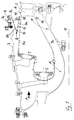
- Reference number 1 denotes an annular combustion chamber of a gas turbine, which is designed here as a stepped combustion chamber and thus next to one
- a plurality of ring-shaped pilot burners 2 furthermore on the end face also has annularly arranged main burners 3.
- the combustion chamber 1 is on a housing wall 7 surrounding the entire combustion chamber structure.
- An annular, kinked design is provided for this Arm structure 8, located on the end portion of the outer combustion chamber wall 9a connects.
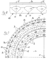
- openings 13 in the arm structure 8 or in the legs 8a, 8b are so-called openings 13 in the arm structure 8 or in the legs 8a, 8b. If these openings or openings 13 in at least one the leg 8a, 8b, but preferably suitable in both legs 8a, 8b dimensioned and arranged, the arm structure 8 acts similar to one Leaf spring with customizable spring characteristics. Best results were with the design and arrangement explained below achieved by openings 13 in the arm structure 8.
- the openings 13 are dovetail-shaped designed and distributed equally over the circumference of both legs 8a, 8b arranged, the narrowest portions of the openings of each Kink line 10 of the arm structure 8 are facing.
- the breakthroughs 13 open to the crease line, so that - after these openings in the outer leg 8b and in the inner leg 8a in the illustration 1, so to speak, one above the other - between each breakdown 13 in the outer leg 8b and the adjacent opening 13 there is a so-called connection gap 14 in the inner leg 8a.
- the stepped ring combustion chamber shown here 1 the pilot burner 2 and the main burner 3 offset in the circumferential direction arranged to each other.
- An optimal combustion chamber suspension according to the invention results when in the section plane 15 of each burner (this section plane 15 runs through the Burner 2 or 3 itself and at least through the gas turbine longitudinal axis 11) in one of the legs 8a or 8b, but preferably in both of the Leg 8a, 8b an opening 13 is provided, in this Section plane 15 also the so-called connection gap 14 comes to rest.
- openings 13 with respect to the burners 2 it is also possible to have the openings 13 with respect to the burners 2 to be arranged offset in the circumferential direction, so that then the cutting planes 15 of the individual burners 2, 3, for example, exactly in the middle between two each other neighboring openings 13 would come to rest (not shown).
- any other intermediate positions of the are also possible Openings 13 in the legs 8a and / or 8b with respect to the burner cutting planes 15.
- this quotient (Number of breakthroughs) / (total number of burners) "but also assume other useful values, for example 0.5 or 1.5 but also 2 or 2.5 or 3, the integer values of this quotient taking the advantage of simple periodic ones
- different numerical values for the quotient mentioned can be useful than in the case of stepped combustion chambers (as shown here).
- the inner combustion chamber wall 9b has a receptacle at the end 16 for the guide vane ring adjoining the combustion chamber 1 6, so that this over the combustion chamber 1 and its advantageous Suspension is also kept in an optimal manner.
Landscapes
- Engineering & Computer Science (AREA)
- Mechanical Engineering (AREA)
- General Engineering & Computer Science (AREA)
- Chemical & Material Sciences (AREA)
- Combustion & Propulsion (AREA)
- Turbine Rotor Nozzle Sealing (AREA)
Applications Claiming Priority (2)
| Application Number | Priority Date | Filing Date | Title |
|---|---|---|---|
| DE19745683A DE19745683A1 (de) | 1997-10-16 | 1997-10-16 | Aufhängung einer ringförmigen Gasturbinen-Brennkammer |
| DE19745683 | 1997-10-16 |
Publications (3)
| Publication Number | Publication Date |
|---|---|
| EP0909924A2 true EP0909924A2 (fr) | 1999-04-21 |
| EP0909924A3 EP0909924A3 (fr) | 2000-08-02 |
| EP0909924B1 EP0909924B1 (fr) | 2003-07-16 |
Family
ID=7845693
Family Applications (1)
| Application Number | Title | Priority Date | Filing Date |
|---|---|---|---|
| EP98117869A Expired - Lifetime EP0909924B1 (fr) | 1997-10-16 | 1998-09-21 | Suspension d'une chambre de combustion annulaire de turbine à gaz |
Country Status (3)
| Country | Link |
|---|---|
| US (1) | US6131384A (fr) |
| EP (1) | EP0909924B1 (fr) |
| DE (2) | DE19745683A1 (fr) |
Families Citing this family (17)
| Publication number | Priority date | Publication date | Assignee | Title |
|---|---|---|---|---|
| FR2825783B1 (fr) | 2001-06-06 | 2003-11-07 | Snecma Moteurs | Accrochage de chambre de combustion cmc de turbomachine par pattes brasees |
| FR2825781B1 (fr) | 2001-06-06 | 2004-02-06 | Snecma Moteurs | Montage elastique de chambre ce combustion cmc de turbomachine dans un carter metallique |
| FR2825784B1 (fr) * | 2001-06-06 | 2003-08-29 | Snecma Moteurs | Accrochage de chambre de combustion cmc de turbomachine utilisant les trous de dilution |
| FR2825782A1 (fr) * | 2001-06-06 | 2002-12-13 | Snecma Moteurs | Montage flottant radial de chambre de combustion cmc de turbomachine dans un carter metallique |
| FR2825785B1 (fr) | 2001-06-06 | 2004-08-27 | Snecma Moteurs | Liaison de chambre de combustion cmc de turbomachine en deux parties |
| FR2825787B1 (fr) * | 2001-06-06 | 2004-08-27 | Snecma Moteurs | Montage de chambre de combustion cmc de turbomachine par viroles de liaison souples |
| SE519323C2 (sv) * | 2001-06-28 | 2003-02-11 | Volvo Aero Ab | Moduluppbyggd gasturbin |
| FR2829228B1 (fr) * | 2001-08-28 | 2005-07-15 | Snecma Moteurs | Chambre de combustion annulaire a double tete etagee |
| FR2840974B1 (fr) * | 2002-06-13 | 2005-12-30 | Snecma Propulsion Solide | Anneau d'etancheite pour cahmbre de combustion et chambre de combustion comportant un tel anneau |
| US7025563B2 (en) * | 2003-12-19 | 2006-04-11 | United Technologies Corporation | Stator vane assembly for a gas turbine engine |
| US7229247B2 (en) * | 2004-08-27 | 2007-06-12 | Pratt & Whitney Canada Corp. | Duct with integrated baffle |
| FR2890156A1 (fr) * | 2005-08-31 | 2007-03-02 | Snecma | Chambre de combustion d'une turbomachine |
| US7909570B2 (en) * | 2006-08-25 | 2011-03-22 | Pratt & Whitney Canada Corp. | Interturbine duct with integrated baffle and seal |
| FR2913051B1 (fr) * | 2007-02-28 | 2011-06-10 | Snecma | Etage de turbine dans une turbomachine |
| US8511089B2 (en) * | 2009-07-31 | 2013-08-20 | Rolls-Royce Corporation | Relief slot for combustion liner |
| EP2397762A1 (fr) * | 2010-06-17 | 2011-12-21 | Siemens Aktiengesellschaft | Dispositif amortisseur pour amortir les variations de pression dans la chambre de combustion d'une turbine |
| DE102015212573A1 (de) * | 2015-07-06 | 2017-01-12 | Rolls-Royce Deutschland Ltd & Co Kg | Gasturbinenbrennkammer mit integriertem Turbinenvorleitrad sowie Verfahren zu deren Herstellung |
Citations (1)
| Publication number | Priority date | Publication date | Assignee | Title |
|---|---|---|---|---|
| EP0564172A1 (fr) | 1992-03-30 | 1993-10-06 | General Electric Company | Chambre de combustion annulaire double |
Family Cites Families (13)
| Publication number | Priority date | Publication date | Assignee | Title |
|---|---|---|---|---|
| US2702987A (en) * | 1952-06-11 | 1955-03-01 | Nicolin Curt Rene | Expansible element for connecting pipes of different diameters |
| US3670497A (en) * | 1970-09-02 | 1972-06-20 | United Aircraft Corp | Combustion chamber support |
| GB1578474A (en) * | 1976-06-21 | 1980-11-05 | Gen Electric | Combustor mounting arrangement |
| FR2402068A1 (fr) * | 1977-09-02 | 1979-03-30 | Snecma | Chambre de combustion anti-pollution |
| US4191011A (en) * | 1977-12-21 | 1980-03-04 | General Motors Corporation | Mount assembly for porous transition panel at annular combustor outlet |
| US4483149A (en) * | 1982-05-20 | 1984-11-20 | United Technologies Corporation | Diffuser case for a gas turbine engine |
| US5323605A (en) * | 1990-10-01 | 1994-06-28 | General Electric Company | Double dome arched combustor |
| US5161940A (en) * | 1991-06-21 | 1992-11-10 | Pratt & Whitney Canada, Inc. | Annular support |
| CA2070518C (fr) * | 1991-07-01 | 2001-10-02 | Adrian Mark Ablett | Ensemble dome pour chambre de combustion |
| US5333443A (en) * | 1993-02-08 | 1994-08-02 | General Electric Company | Seal assembly |
| FR2723177B1 (fr) * | 1994-07-27 | 1996-09-06 | Snecma | Chambre de combustion comportant une double paroi |
| DE19600837A1 (de) * | 1996-01-12 | 1997-07-17 | Bmw Rolls Royce Gmbh | Axial gestufte Ring-Brennkammer einer Gasturbine |
| US5619855A (en) * | 1995-06-07 | 1997-04-15 | General Electric Company | High inlet mach combustor for gas turbine engine |
-
1997
- 1997-10-16 DE DE19745683A patent/DE19745683A1/de not_active Withdrawn
-
1998
- 1998-08-14 US US09/134,578 patent/US6131384A/en not_active Expired - Fee Related
- 1998-09-21 EP EP98117869A patent/EP0909924B1/fr not_active Expired - Lifetime
- 1998-09-21 DE DE59809015T patent/DE59809015D1/de not_active Expired - Lifetime
Patent Citations (1)
| Publication number | Priority date | Publication date | Assignee | Title |
|---|---|---|---|---|
| EP0564172A1 (fr) | 1992-03-30 | 1993-10-06 | General Electric Company | Chambre de combustion annulaire double |
Also Published As
| Publication number | Publication date |
|---|---|
| DE19745683A1 (de) | 1999-04-22 |
| US6131384A (en) | 2000-10-17 |
| EP0909924A3 (fr) | 2000-08-02 |
| DE59809015D1 (de) | 2003-08-21 |
| EP0909924B1 (fr) | 2003-07-16 |
Similar Documents
| Publication | Publication Date | Title |
|---|---|---|
| EP0909924B1 (fr) | Suspension d'une chambre de combustion annulaire de turbine à gaz | |
| EP0265633B1 (fr) | Turbine axiale | |
| EP0799973B1 (fr) | Contour de paroi pour une turbomachine axiale | |
| EP1193451A2 (fr) | Tête de chambre de combustion d'une turbine à gaz | |
| DE2906365A1 (de) | Turbinenschaufel | |
| EP1004748A2 (fr) | Rotor pour une turbomachine | |
| DE69319497T2 (de) | Axialturbine | |
| DE102014223975A1 (de) | Leitschaufelkranz und Strömungsmaschine | |
| EP1148209A2 (fr) | Configuration de joint inter-étages | |
| EP2126321A1 (fr) | Turbine à gaz présentant une couronne directrice et un mélangeur | |
| DE112020004602B4 (de) | Turbinenflügel | |
| EP2818724A1 (fr) | Turbomachine, structure de circulation et procédé | |
| DE2016283A1 (de) | Turb inens chaufelabdec kung | |
| EP3245451B1 (fr) | Chambre de combustion pour turbine à gaz, délimitée par une paroi | |
| CH660209A5 (de) | Verbindungsvorrichtung zwischen einem keramischen bauteil und einer metallstruktur. | |
| CH634139A5 (de) | Einrichtung zum verringern der rauchdichte eines brenners. | |
| DE2514208A1 (de) | Gasturbine der scheibenbauart | |
| EP1288435A2 (fr) | Aube de turbine avec au moins un orifice de refroidissement | |
| DE60023093T2 (de) | Inverter-Kanalanordnung für Doppelbläser Konzept | |
| EP3321589A1 (fr) | Buse de carburant d'une turbine à gaz dotée du générateur de tourbillons | |
| CH622584A5 (fr) | ||
| DE2257076C3 (de) | Trommelläufer für Axialverdichter | |
| DE2355547A1 (de) | Doppelwandiger brenner mit aufprallkuehlung | |
| DE102012002465A1 (de) | Gasturbinenbrennkammer mit unsymmetrischen Kraftstoffdüsen | |
| EP1423647A1 (fr) | Dispositif a chambre de combustion |
Legal Events
| Date | Code | Title | Description |
|---|---|---|---|
| PUAI | Public reference made under article 153(3) epc to a published international application that has entered the european phase |
Free format text: ORIGINAL CODE: 0009012 |
|
| AK | Designated contracting states |
Kind code of ref document: A2 Designated state(s): DE FR GB |
|
| AX | Request for extension of the european patent |
Free format text: AL;LT;LV;MK;RO;SI |
|
| RAP1 | Party data changed (applicant data changed or rights of an application transferred) |
Owner name: ROLLS-ROYCE DEUTSCHLAND GMBH |
|
| PUAL | Search report despatched |
Free format text: ORIGINAL CODE: 0009013 |
|
| AK | Designated contracting states |
Kind code of ref document: A3 Designated state(s): AT BE CH CY DE DK ES FI FR GB GR IE IT LI LU MC NL PT SE |
|
| AX | Request for extension of the european patent |
Free format text: AL;LT;LV;MK;RO;SI |
|
| RAP1 | Party data changed (applicant data changed or rights of an application transferred) |
Owner name: ROLLS-ROYCE DEUTSCHLAND LTD & CO KG |
|
| 17P | Request for examination filed |
Effective date: 20010201 |
|
| AKX | Designation fees paid |
Free format text: DE FR GB |
|
| GRAH | Despatch of communication of intention to grant a patent |
Free format text: ORIGINAL CODE: EPIDOS IGRA |
|
| GRAH | Despatch of communication of intention to grant a patent |
Free format text: ORIGINAL CODE: EPIDOS IGRA |
|
| GRAA | (expected) grant |
Free format text: ORIGINAL CODE: 0009210 |
|
| AK | Designated contracting states |
Designated state(s): DE FR GB |
|
| REG | Reference to a national code |
Ref country code: GB Ref legal event code: FG4D Free format text: NOT ENGLISH |
|
| REF | Corresponds to: |
Ref document number: 59809015 Country of ref document: DE Date of ref document: 20030821 Kind code of ref document: P |
|
| GBT | Gb: translation of ep patent filed (gb section 77(6)(a)/1977) |
Effective date: 20031117 |
|
| ET | Fr: translation filed | ||
| PLBE | No opposition filed within time limit |
Free format text: ORIGINAL CODE: 0009261 |
|
| STAA | Information on the status of an ep patent application or granted ep patent |
Free format text: STATUS: NO OPPOSITION FILED WITHIN TIME LIMIT |
|
| 26N | No opposition filed |
Effective date: 20040419 |
|
| PGFP | Annual fee paid to national office [announced via postgrant information from national office to epo] |
Ref country code: GB Payment date: 20090929 Year of fee payment: 12 |
|
| PGFP | Annual fee paid to national office [announced via postgrant information from national office to epo] |
Ref country code: DE Payment date: 20090929 Year of fee payment: 12 |
|
| GBPC | Gb: european patent ceased through non-payment of renewal fee |
Effective date: 20100921 |
|
| REG | Reference to a national code |
Ref country code: FR Ref legal event code: ST Effective date: 20110531 |
|
| REG | Reference to a national code |
Ref country code: DE Ref legal event code: R119 Ref document number: 59809015 Country of ref document: DE Effective date: 20110401 |
|
| PG25 | Lapsed in a contracting state [announced via postgrant information from national office to epo] |
Ref country code: FR Free format text: LAPSE BECAUSE OF NON-PAYMENT OF DUE FEES Effective date: 20100930 Ref country code: DE Free format text: LAPSE BECAUSE OF NON-PAYMENT OF DUE FEES Effective date: 20110401 |
|
| PG25 | Lapsed in a contracting state [announced via postgrant information from national office to epo] |
Ref country code: GB Free format text: LAPSE BECAUSE OF NON-PAYMENT OF DUE FEES Effective date: 20100921 |
|
| PGFP | Annual fee paid to national office [announced via postgrant information from national office to epo] |
Ref country code: FR Payment date: 20091006 Year of fee payment: 12 |