EP0908797B1 - Elektronische Uhr - Google Patents
Elektronische Uhr Download PDFInfo
- Publication number
- EP0908797B1 EP0908797B1 EP98204248A EP98204248A EP0908797B1 EP 0908797 B1 EP0908797 B1 EP 0908797B1 EP 98204248 A EP98204248 A EP 98204248A EP 98204248 A EP98204248 A EP 98204248A EP 0908797 B1 EP0908797 B1 EP 0908797B1
- Authority
- EP
- European Patent Office
- Prior art keywords
- dynamo
- wheel
- wheel train
- wall portion
- electronic watch
- Prior art date
- Legal status (The legal status is an assumption and is not a legal conclusion. Google has not performed a legal analysis and makes no representation as to the accuracy of the status listed.)
- Expired - Lifetime
Links
Images


Classifications
-
- G—PHYSICS
- G04—HOROLOGY
- G04B—MECHANICALLY-DRIVEN CLOCKS OR WATCHES; MECHANICAL PARTS OF CLOCKS OR WATCHES IN GENERAL; TIME PIECES USING THE POSITION OF THE SUN, MOON OR STARS
- G04B5/00—Automatic winding up
- G04B5/02—Automatic winding up by self-winding caused by the movement of the watch
- G04B5/16—Construction of the weights
-
- G—PHYSICS
- G04—HOROLOGY
- G04B—MECHANICALLY-DRIVEN CLOCKS OR WATCHES; MECHANICAL PARTS OF CLOCKS OR WATCHES IN GENERAL; TIME PIECES USING THE POSITION OF THE SUN, MOON OR STARS
- G04B31/00—Bearings; Point suspensions or counter-point suspensions; Pivot bearings; Single parts therefor
- G04B31/004—Bearings; Point suspensions or counter-point suspensions; Pivot bearings; Single parts therefor characterised by the material used
- G04B31/012—Metallic bearings
- G04B31/0123—Metallic bearings with metallic ball bearings and metallic roller bearings
-
- G—PHYSICS
- G04—HOROLOGY
- G04B—MECHANICALLY-DRIVEN CLOCKS OR WATCHES; MECHANICAL PARTS OF CLOCKS OR WATCHES IN GENERAL; TIME PIECES USING THE POSITION OF THE SUN, MOON OR STARS
- G04B31/00—Bearings; Point suspensions or counter-point suspensions; Pivot bearings; Single parts therefor
- G04B31/08—Lubrication
-
- G—PHYSICS
- G04—HOROLOGY
- G04C—ELECTROMECHANICAL CLOCKS OR WATCHES
- G04C10/00—Arrangements of electric power supplies in time pieces
-
- G—PHYSICS
- G04—HOROLOGY
- G04C—ELECTROMECHANICAL CLOCKS OR WATCHES
- G04C3/00—Electromechanical clocks or watches independent of other time-pieces and in which the movement is maintained by electric means
- G04C3/008—Mounting, assembling of components
Definitions
- the present invention relates to an electronic watch including a so-called automatic winding dynamo, and more particularly to a technology for improving the structure of such an electronic watch to achieve a reduction in thickness.
- a power supply section 10 is made up of a small-sized dynamo 20 and a secondary power supply 30, and a stepping motor 40 is driven by power supplied from the power supply section 10.
- a watch wheel train 50 is operatively connected to a motor rotor 42 of the stepping motor 40 so that, for example, a second hand 161 attached to a second wheel 52 is intermittently rotated in steps of 6° for each second.
- the small-sized dynamo 20 comprises a dynamo rotor 21 rotated by torque transmitted to it, a dynamo stator 22 disposed in surrounding relation to the dynamo rotor 21, and a dynamo coil 23 wound over a magnetic core 24 making up a magnetic circuit in cooperation with the dynamo stator 22 and the dynamo rotor 21.
- a dynamo wheel train 60 for transmitting rotation of a oscillating weight 25 while speeding up the rotation is operatively connected to the dynamo rotor 21.
- a rotational shaft of the dynamo rotor 21 and a rotational shaft of the dynamo wheel train 60 are each often supported by a small and simple bearing formed of a hole jewel.
- a lubricant applied to the rotational shaft tends to scatter to the surroundings upon rotation of the rotational shaft. If the scattered lubricant adheres to the watch wheel train 50, the lubricant may cause abnormal motion in driving the hands, such as stop or delay of any of gears, due to its viscosity. This raises a problem in the conventional electronic watches with hands that the parts cannot be arranged in closer relation and hence the thickness of the watch cannot be reduced.
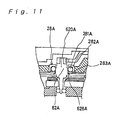
- one of the gears of the dynamo wheel train which tends to be easily subject to lateral pressure such as a dynamo rotor transmitting wheel 62A (see Fig. 1), is sometimes supported at its rotational shaft 20A by a ball bearing 28A.
- the ball bearing 28A comprises a plurality of balls 281A arranged around the rotational shaft 620A of the dynamo rotor transmitting wheel 62A, a ring-shaped frame piece 282A holding the balls 281A, and a retainer piece 283A positioned adjacent the frame piece 282A to cooperate with it to prevent the balls 281A from slipping off.
- the balls 281A are held in contact with the rotational shaft 620A to restrict a lateral inclination of the rotational shaft 620A.
- the rotational shaft 620A has a stepped portion 626A formed around it, and the stepped portion 626A abuts against the retainer piece 283A to restrict the position of the rotational shaft 620A in the axial direction.
- the bearing structure shown in Fig. 11 has a problem that large friction resistance generates between the stepped portion 626A and the retainer piece 283A when the rotational shaft 620A is rotated.
- Generation of large friction resistance means that wasteful excessive force is required to rotate the rotational shaft 620A, and that the stepped portion 626A or the retainer piece 283A is severely worn away.
- a novel bearing structure capable of solving the above-stated problems.
- even a bearing structure which has succeeded in solving the above-stated problems cannot be practically adopted if it requires a larger space, because such a bearing structure prevents a reduction in thickness of electronic watches with hands.
- an object of the present invention is to provide a construction of an electronic watch with a built-in dynamo, which can improve structures of parts themselves arranged inside the watch and layout of the parts, and can reduce a total thickness of the electronic watch.
- an electronic watch having a base on which are mounted a dynamo including a dynamo wheel train for transmitting external force to a dynamo rotor, a secondary power supply for storing electric energy generated by said dynamo, a circuit section including a driving circuit supplied with power from said secondary power supply, a stepping motor driven by said driving circuit, and a watch wheel train for transmitting torque from said stepping motor to a time indicating member, wherein:
- the part of the circuit section which is arranged in the circuit part installation holes in the rotating area of the thicker wall portion is an electronic part making up the driving circuit.
- a wheel train setting lever operatively connected to a setting lever is arranged on the base in the rotating area of the thinner wall portion, the wheel train setting lever stopping motion of the watch wheel train when the setting lever is operated upon external operation applied to an external operating member.
- a reset lever operatively connected to the setting lever and serving as a switch for temporarily stopping and restarting rotation of the stepping motor may be arranged in the circuit part installation hole.
- the base may comprise a metallic main plate and a circuit support seat made of insulating material.
- the circuit part installation hole is formed in the circuit support seat.
- a screw fastening portion of an oscillating weight support for supporting the oscillating weight and the dynamo wheel train through respective bearings may be disposed on the base in the rotating area of the thinner wall portion.
- the oscillating weight support is entirely disposed on the base in the rotating area of the thinner wall portion.
- Fig. 1 is a schematic exploded view showing the general construction of an electronic watch.
- a basic structure of the electronic watch of this embodiment is similar to that of a conventional electronic watch. Therefore, components having functions common to the electronic watch of this embodiment and the conventional electronic watch are denoted by the same reference numerals in the following description.
- an electronic watch 1 with hands of this embodiment is an analog quartz wrist watch of type indicating the time of day by the hands.
- a stepping motor 40 is driven in accordance with a signal output from a crystal oscillator 32 mounted on a circuit board 31.
- the stepping motor 40 comprises a motor rotor 42 having a permanent magnet magnetized into two poles, a motor stator 43 having a cylindrical rotor installation hole 430 in which the motor rotor 42 is disposed, and a coil block formed by winding a coil 41 over a magnetic core 44.
- a watch wheel train 50 comprised of a fifth wheel 51, a second wheel 52, a third wheel 53, a center wheel 54, a minute wheel 55 and a hour wheel 56 is operatively connected to the motor rotor 42 through respective pinions.
- a second hand 161 is fixed to the distal end of a shaft of the second wheel 52 of the watch wheel train.
- a minute hand 162 is fixed to the distal end of a cylindrical shaft of the center wheel 54.
- An hour hand 163 is fixed to the distal end of a cylindrical shaft of the hour wheel 56.
- a speed reducing ratio achieved through the gearing from the motor rotor 42 to the second wheel 52 is set to 1/30.
- the second hand 161 is constructed such that it is intermittently rotated in steps of 6° whenever the motor rotor 42 is intermittently rotated in steps of 180° for each second.
- a power supply section 10 for driving the stepping motor 40 is primarily made up of a small-sized dynamo 20 and a secondary power supply 30 (capacitor).
- the small-sized dynamo 20 comprises an eccentric oscillating weight 25 rotatable in response to the wrist movement, a dynamo rotor 21 rotated by receiving kinetic energy from the oscillating weight 25, a dynamo stator 22 disposed in surrounding relation to the dynamo rotor 21, and a dynamo coil 23 wound over a magnetic core 24 making up a magnetic circuit in cooperation with the dynamo stator 22 and the dynamo rotor 21.
- the oscillating weight 25 and the dynamo rotor 21 are operatively interconnected through a dynamo wheel train 60 for transmitting rotation of the oscillating weight 25 while speeding up the rotation.
- the dynamo wheel train 60 is made up of a oscillating weight wheel 61 formed integrally with the oscillating weight 25, and a dynamo rotor transmitting wheel 62 having a pinion held in mesh with the oscillating weight wheel 61.
- the dynamo rotor 21 has a permanent magnet magnetized to have N and S poles which are rotated when the rotation of the oscillating weight 25 is transmitted to the dynamo rotor 21. Accordingly, induced electromotive force can be taken out of the dynamo coil 23 and charged into the secondary power supply 30.
- the oscillating weight 25 has, though described later in more detail, a oscillating weight fixing screw 250 attached to its rotating central portion.
- the oscillating weight 25 is formed such that its inner peripheral portion around the oscillating weight fixing screw 250 (rotating central portion) provides a thinner wall portion 251 as a light oscillating weight, and its outer peripheral portion provides a thicker wall portion 252 as a heavy oscillating weight stretching radially outward from the light oscillating weight.
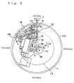
- Fig. 2 is an explanatory view showing the layout, as viewed from above, of the small-sized dynamo and other parts in the electronic watch with hands of this embodiment
- Fig. 3 is an explanatory view showing the layout, as viewed from above, of the stepping motor, the watch wheel train, the circuit board, etc. in the electronic watch with hands.
- Fig. 2 is a plan view showing a state where principal parts are mounted on a main plate constituting a base in the electronic watch with hands of this embodiment.
- a central portion of a main plate 200 serves as the center of rotation of the oscillating weight 25 and the hands.
- a dial of the watch is disposed on the rear side of the main plate 200, and the time of day is indicated on the drawing at corresponding angular positions of the main plate 200.
- a rotating area of the oscillating weight 25 is indicated by a two-dot-chain line L1 positioned slightly inward of an outer peripheral edge of the main plate 200.
- a two-dot-chain line L1 positioned slightly inward of an outer peripheral edge of the main plate 200.
- another two-dot-chain line L2 representing a boundary between a rotating area of the thinner wall portion 251 of the oscillating weight 25 and a rotating area of the thicker wall portion 252 thereof.
- the small-sized dynamo 20 is arranged in the rotating area of the oscillating weight 25 so as to extend over both the rotating area cf the thinner wall portion 251 and the rotating area of the thicker wall portion 252.
- the dynamo rotor transmitting wheel 62 is meshed with a pinion 210 of the motor rotor 21, and the oscillating weight wheel 61 fixed to the oscillating weight 25 is meshed with a pinion 620 of the dynamo rotor transmitting wheel 62.
- the dynamo rotor transmitting wheel 22, the motor rotor 21, etc., as well as the oscillating weight wheel 61, which are parts of the dynamo wheel train 60 having relatively large height, are all arranged in the rotating area of the thinner wall portion 251.
- the oscillating weight 25 and the dynamo wheel train 60 are both supported by a oscillating weight support 26 in the form of a flat plate.
- the oscillating weight support 26 is also entirely disposed in the rotating area of the thinner wall portion 251. Further, the oscillating weight support 26 is fixed to the main plate 200 by three screws 267, 268, 269 any of which is positioned in the rotating area of the thinner wall portion 251.
- the thickness of the electronic watch 1 with hands can be reduced.
- the electronic watch 1 can be easily disassembled because the oscillating weight support 26 can be removed in its entirety if the oscillating weight 25 is removed.
- the watch wheel train 50 comprised of the fifth wheel 51, the second wheel 52, the third wheel 53, the center wheel 54, the minute wheel 55 and the hour wheel 56 which have each a relatively large height.
- the thicker wall portion 252 is provided as the heavy oscillating weight in the outer peripheral portion of the oscillating weight 25 for the purpose of increasing weight unbalance of the oscillating weight 25 in the angular direction, no trouble occurs in arrangement of the train wheels. Further, an area of the thinner wall portion 251 can be enlarged corresponding to increased weight unbalance of the oscillating weight 25, thereby securing a larger space for arrangement of the other parts. Thus, the above structure is advantageous in achieving a reduction in thickness of the electronic watch 1 with hands.
- relatively thin members are arranged in the rotating area of the thicker wall portion 252 of the oscillating weight 25.
- the circuit board 31 formed of a flexible board, on which diodes 33, etc. making up a driving circuit are mounted is relatively thin, it is arranged in the rotating area of the thicker wall portion 252 of the oscillating weight 25 by utilizing a gap between the thicker wall portion 252 of the oscillating weight 25 and the main plate 200.
- circuit part installation holes formed in the circuit support seat 311.
- the circuit support seat 311 is utilized to receive the diodes 33, etc. in the through-holes 205. Therefore, more than half of electronic parts mounted on the circuit board 31 and making up the driving circuit can be arranged in the rotating area of the thicker wall portion 252 where the gap size between the oscillating weight and main plate is small. In addition, since those electronic parts are surrounded by the insulating circuit support seat 311 fitted to the inner peripheral surfaces of the through-holes 206 in the main plate 200, a trouble such as a short-circuit is surely prevented.
- Fig. 5 is an explanatory view showing the positional relationship, as viewed from above, between parts of a mechanism for adjusting the indicated time of day in the electronic watch with hands according to the embodiment.
- the electronic watch 1 with hands also includes a mechanism for adjusting the second hand, etc. by the user operating a crown 7 (external operating member) from the outside.
- This mechanism is constructed as follows.
- a setting lever 71 engages with a shaft coupled to the crown 7, and the position of the setting lever 71 is restricted by a yoke holder 76.
- a yoke 72 engages in a groove of a sliding pinion 73 which is coupled to the shaft of the crown 7. Therefore, when the crown 7 is pulled outward one step, the setting lever 71 is rotated in the direction of arrow A.
- a dowel formed on the setting lever 71 engages in a cam slot of a train wheel setting lever 74.
- the train wheel setting lever 74 is rotated in the direction of arrow B to engage with the fifth wheel 51, thereby stopping motion of the second hand 161.
- the minute wheel 55 and so forth can be rotated through a setting wheel 79.
- a reset lever 75 is also connected to the setting lever 71 through a cam mechanism.
- the reset lever 75 is rotated in the direction of arrow C.
- a contact portion 315 extending from the circuit board 31 is positioned on the side toward which the reset lever 75 is rotated. In interlock with the pulling-out of the crown 7 in one step, therefore, the contact portion 315 is pushed by the reset lever 75 to actuate a switch. In this state, output of a driving signal to the stepping motor 40 from the driving circuit (not shown) constructed on the circuit board 31 is stopped and the motor rotor 42 also stops its rotation.
- the reset lever 75 and the train wheel setting lever 74 are each formed of a relatively thin plate member. Of these two levers, the train wheel setting lever 74 acts directly on the fifth gear 51 and therefore it is required to locate in a central portion of the main plate 200. Thus, the train wheel setting lever 74 is disposed in the rotating area of the thinner wall portion 251 of the oscillating weight 25 (i.e., between the rotating level of the thinner wall portion 251 of the oscillating weight 25 and the main plate 200).
- the reset lever 75 is formed of a thin metallic plate and is just required to position in such a manner as able to contact part of the circuit board 31. Accordingly, the reset lever 75 is arranged in the rotating area of the thicker wall portion 252 of the oscillating weight 25 (i.e., between the rotating level of the thicker wall portion 252 of the oscillating weight 25 and the main plate 200).
- the reset lever 75 formed of a metallic plate also constitutes part of the circuit section. Further, the reset lever 75 is arranged close to the main plate 200 as with the diodes 33 on the circuit board 31 which have been described above in connection with Fig. 4. Specifically, in this embodiment, the reset lever 75 is arranged in a recess 207 (circuit part installation hole) of the insulating circuit support seat 311 which is fitted to a through-hole 208 of the main plate 200.
- the circuit support seat 311 is utilized to receive the reset lever 75 in the circuit part installation hole defined by the recess 207. Therefore, the reset lever 75 can be arranged in the rotating area of the thicker wall portion 252 where the gap size between the oscillating weight and main plate is small. In addition, since the reset lever 75 is surrounded by the insulating circuit support seat 311, a trouble such as a short-circuit is surely prevented.
- changeover members such as the setting lever 71 and the yoke 72 are firmly held down by the yoke holder 76 in the rotating area of the thicker wall portion 252 of the oscillating weight 25 (i.e., between the rotating level of the thicker wall portion 252 of the oscillating weight 25 and the main plate 200).
- the thickness of the electronic watch 1 with hands of this embodiment is reduced by sufficiently utilizing not only the rotating area of the thinner wall portion 251 of the oscillating weight 25, but also the narrow gap between the thicker wall portion 252 of the oscillating weight 25 and the main plate 200.
- the circuit board 31 is positioned by fitting a hole 310 formed in the circuit board 31 over a corresponding projection 312 on the circuit support seat 311, and it is simultaneously firmly held down by a circuit retainer plate 310. Also, as will be seen from Fig. 7(b), a portion of the end of the circuit board 31 is laterally extended to provide a contact 315.
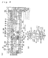
- Fig. 8 is a vertical sectional view of the watch wheel train and thereabout assembled in the electronic watch with hands of this embodiment
- Fig. 9(A) is a vertical sectional view of the dynamo wheel train and thereabout assembled in the electronic watch with hands
- Fig. 9(B) is an enlarged view of a bearing portion supporting the rotational shaft of the dynamo rotor
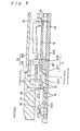
- Fig. 10 is a vertical sectional view of the small-sized dynamo and thereabout assembled in the electronic watch with hands.
- the oscillating weight 25 is fixed in place by the oscillating weight fixing screw 250 through a ball bearing 27 which is in turn fixed to the oscillating weight support 26.
- a wheel train bridge 80 is disposed between the ball bearing 27 and the main plate 200.
- One axial ends of rotational shafts 530, 510 of the third wheel 53 and the fifth wheel 51 are supported through hole jewels 531, 511 in holes 801, 802 formed in the wheel train bridge 80, respectively.
- the other axial ends of the rotational shafts 530, 510 of the third wheel 53 and the fifth wheel 51 are supported through hole jewels 532, 512 in holes 201, 202 formed in the main plate 200, respectively.
- An outer peripheral portion of the hour wheel 56 is extended outward to a position overlapping the hole jewels 532, 512 for the third wheel 53 and the fifth wheel 51.
- the hour wheel 56 has opposite end surfaces shaped such that one of the end surfaces on which the hour hand locates is cut to hollow slightly in its inner peripheral portion 561, and the other end surface is cut to hollow slightly in its outer peripheral portion 562. This structure surely defines a gap G1 between the hour wheel 56 and the hole jewels 532, 512 for holding a lubricant in place.
- a dial 3 of the watch is layered on the main plate 200. Holes 301 are formed in the dial 3 so that the rotational shaft of each train wheel can penetrate the dial 3 through the corresponding hole.
- the dial 3 is arranged to extend along one of the end surfaces of the hour wheel 56 on which the hour hand locates. Because the inner peripheral portion 561 cf the hour wheel 56 is cut to hollow slightly in the one end surface on which the hour hand locates, a conical plate spring 303 can be interposed between the inner peripheral portion 561 of the hour wheel 56 and the dial 3. Thus, by fitting one piece of conical plate spring 303 over the hour wheel 56 to position between the hour wheel 56 and the dial 3, it is possible to keep the hour wheel 56 and the dial 3 away from each other by a distance represented by a gap G2 in the inner peripheral portion 561 of the hour wheel 56.
- the burrs would not impede the rotation of the hour wheel 56.
- the gap G2 is surely maintained by the presence of the conical plate spring 303 and the hollowed inner peripheral portion 561 of the hour wheel 56, the spacing between the hour wheel 56 and the dial 3 can be set to a necessary minimum size. This also contributes to reducing the thickness of the electronic watch 1 with hands.
- the dynamo rotor transmitting wheel 62 which is one of the wheels making up the dynamo wheel train 60 and has the pinion 621 held in mesh with the oscillating weight wheel 61, is supported between the oscillating weight support 26 and the main plate 200.
- the rotational shaft 620 of the dynamo rotor transmitting wheel 62 is supported at its one axial end by a ball bearing 28 which is held in a hole 263 formed in the oscillating weight support 26.
- the ball bearing 28 comprises a plurality of balls 281 arranged around the rotational shaft 620 and a ring-shaped frame 280 for accommodating the balls 281 therein.
- the frame 280 comprises a ring-shaped frame piece 282 for holding the balls 281 from two directions, and a retainer piece 283 positioned adjacent the frame piece 282 for cooperating with it to prevent the balls 281 from slipping off.
- the rotational shaft 620 of the dynamo rotor transmitting wheel 62 has a stepped portion 626 formed in opposite relation to the retainer piece 283.
- the balls 281 are partly projecting out of a gap between an inner peripheral edge of the retainer piece 283 (inner peripheral edge of one of both end surfaces of the frame 280 on the side where the stepped portion 626 locates) and the rotational shaft 620, so that the balls come into abutment against the stepped portion 626.
- the stepped portion 626 and the balls 28 contact with each other through not sliding friction but rolling friction, and hence the load loss of the wheel train can be kept small. Accordingly, in the electronic watch 1 with hands of this embodiment, it is possible to determine fit looseness of the dynamo rotor transmitting wheel 62 with a simple structure and reduce the thickness of the electronic watch. Moreover, since the dynamo rotor transmitting wheel 62, one of the train wheels which is most easily subject to lateral pressure, undergoes relatively small friction in its bearing portion, the efficiency of power generation is increased.
- a wall 804 formed at the end of the wheel train bridge 80 is formed into a wall which locates between the watch wheel train 50 and the dynamo wheel train 60 and serves to prevent scattering of a lubricant. Even with the dynamo rotor transmitting wheel 62 rotating at a high speed, therefore, the lubricant applied to the rotational shaft 620 and the gear portion 623 is prevented from scattering to the third wheel 53, etc.
- the dynamo rotor 21 having the pinion 210 held in mesh with the gear portion 623 of the dynamo rotor transmitting wheel 62 is supported between the oscillating weight support 26 and the main plate 200.
- a hole jewel 212 is fitted over one axial end of a rotational shaft 211 of the dynamo rotor 21.
- the hole jewel 212 is held in a hole 266 formed in the oscillating weight support 26 while it is fitted into a ring-shaped cap 213.
- another hole jewel 214 is fitted over the other axial end of the rotational shaft 211 of the dynamo rotor 21.
- the hole jewel 214 is held in a hole 205 formed in the main plate 200 while it is fitted into a ring-shaped cap 215.
- the bearing portions using the hole jewels 212, 214 and the caps 213, 215 have the same structure. A description, therefore, will now be made primarily on the bearing portion using the hole jewel 214 and the cap 215 with reference to Fig. 9(B).
- the cap 215 not only covers the lateral side of the hole jewel 214, but also partly covers one end surface 216 of the hole jewel 214, which faces the dynamo rotor 21, from the outer side. Accordingly, an annular slot G3 for holding a lubricant between an inner peripheral surface of the cap 215 and an outer circumferential surface of the rotational shaft 211 is defined in a position corresponding to an inner portion of the end surface 216 of the hole jewel 214.
- the annular slot G3 has an opening width in the range of, e.g., about 40 ⁇ m to about 100 ⁇ m. Further, the annular slot G3 has a relatively large depth almost equal to the thickness of the cap 215.
- the lubricant tends to scatter most easily from the bearing portion of the dynamo rotor 21 which is rotated at a maximum speed among the train wheels.
- the rotational shaft 211 of the dynamo rotor 21 is supported by the above-stated bearing structure, scattering of the lubricant can be effectively prevented.
- the cap 215 and the hole jewel 214 are formed as separate parts and assembled such that the hole jewel 214 is fitted into the cap 215.
- this embodiment is practiced by immersing an assembly of the hole jewel 214 and the cap 215 fitted to each other in a treatment solution so that all the surfaces of the hole jewel 214 and the cap 215 are subject to surface treatment for preventing spread of the lubricant.
- a fluorine-base coating is dissolved in a fluorine-base solvent to prepare a treatment solution, and the assembly of the hole jewel 214 and the cap 215 fitted to each other is immersed in the treatment solution.
- the assembly is dried to remove the solvent.
- a thin layer of the fluorine-base coating is formed all over the surfaces of the hole jewel 214 and the cap 215. Because the thin layer of the fluorine-base coating formed by the surface treatment serves to repel the lubricant, the lubricant is prevented from permeating into the space between the hole jewel 214 and the cap 215 and spreading further from there.
- a gap 222 of predetermined size is positively maintained between the cap 215 and the end surface 216 of the hole jewel 214.
- the presence of the gap 222 enables the treatment solution to enter the space between the cap 215 and the hole jewel 214 so sufficiently that the surface treatment for preventing spread of a lubricant can be surely applied to all over the surfaces of the cap 215 and the hole jewel 214. Therefore, the lubricant maintained in the lubricant holding annular slot G3 will not spread through between the cap 215 and the hole jewel 214.
- bosses 219 are projected on the cap 215 to determine a depth of fitting resulted when the hole jewel 214 is fitted into the cap 215.
- the size of the gap 222 is about 10 ⁇ m, for example, taking into account the coating layer of about 1 ⁇ m formed by the surface treatment and the accuracy of machining.
- the rotational shaft 211 has a conical portion 217 formed in its outer circumferential surface near each of both the axial ends supported by the hole jewels 212, 214 such that the diameter of the rotational shaft 211 increases gradually in the conical portion 217 toward the portion where the lubricant holding annular slot G3 is defined. Therefore, even if the lubricant spills and adheres onto the rotational shaft 211, the lubricant adhering onto the conical portion 217 is forced to move toward a larger diameter end of the conical portion 217 (i.e., toward the lubricant holding annular slot G3) under an influence of centrifugal force when the rotational shaft 211 is rotated. As a result, the spilled lubricant is returned to the lubricant holding annular slot G3 and is surely prevented from scattering to the surroundings.
- steps 218 (looseness eliminating steps) projecting in opposite relation to the hole jewels 212, 214 are formed on the outer circumferential surface of the rotational shaft 211. Therefore, if the rotational shaft 211 is shifted in the axial direction, the step 218 comes into abutment against the inner end surface of each of the hole jewels 212, 214, thereby preventing a further shift of the rotational shaft 211.
- the position at which the step 218 is formed on the outer circumferential surface of the rotational shaft 211, and the depth of the annular slot G3 are set so that the step 218 is always located within the lubricant holding annular slot G3 even when the rotational shaft 211 is axially shifted in either direction.
- the depth of the annular slot G3 is set to about 100 ⁇ m or above. Note that since the depth of the annular slot G3 as small as possible is advantageous in reducing the thickness of the electronic watch with hands, the depth of the annular slot G3 is set to a necessary minimum value within the range enough to prevent scattering of the lubricant.
- a lubricant injection recess 220 is formed in the outer end surface of each of the hole jewels 212, 214. Accordingly, when the lubricant is injected and kept in the recess 220, the injected lubricant permeates into openings of the hole jewel 214 and then accumulates in the lubricant holding annular slot G3.
- the recess 220 has an outer diameter D larger than an outer diameter d of the lubricant holding annular slot G3, and also has an inner volume larger than that of the annular slot G3. This ensures that the amounts of the lubricant held by the annular slot G3 and the lubricant injection recess 220, respectively, are balanced.
- the dynamo rotor 21 is located in surrounded relation by the dynamo stator 22.
- the dynamo stator 22 is connected to the magnetic core 24 of the small-sized dynamo 20.
- the magnetic core 24 comprises a lower magnetic core 241 positioned on the main plate 200 and an upper magnetic core 242 placed over the lower magnetic core 241.
- the lower magnetic core 241 is connected to the dynamo stator 22 through a core connecting screw 246 and a screw seat 247.
- the lower magnetic core 241 is extended horizontally beyond the end of the outer magnetic core 242 toward the dynamo stator 22.
- the end of the dynamo stator 22 is bent to provide a joint end 220 which is positioned to lie over an extended portion 240 of the lower magnetic core 241.
- the joint end 220 is machined to have a thinner wall portion 221 in an area where it is fastened by the core connecting screw 246.
- the connecting portion between the dynamo stator 22 and the magnetic core 24 has such a sectional structure that the main plate 200, the magnetic core 24 and the dynamo stator 24 are layered one above another in the order named.
- the joint end 220 (joint portion) of the dynamo stator 22 has an upper surface 222 and a lower surface 223 which are both positioned between an upper surface 224 and a lower surface 225 of the dynamo stator 22 arranged in surrounding relation to the dynamo rotor 211.
- the upper surface 222 of the joint end 220 is positioned at a lower level than an upper surface 211 of the magnet of the dynamo rotor 21. Therefore, the electronic watch 1 with hands according to this embodiment can have a reduced thickness.
- the dynamo stator 22 is machined into the thinner wall portion 221 only in the joint portion thereof with the magnetic core 24, and the other portion of the dynamo stator 22 still remains as a thicker wall portion. Therefore, the extended portion 240 of the lower magnetic core 241 and the thicker wall portion of the dynamo stator 22 can be brought into contact with each other in an area around the joint portion of the dynamo stator 22. That structure prevents a reduction in intensity of the allowable magnetic flux in the area around the joint portion of the dynamo stator 22, and keeps the magnetic flux passing through the magnetic circuit of the small-sized dynamo 20 from leaking out from there. Also, that structure eliminates a need of partly reducing the thickness of the main plate 200 with intent to reduce the thickness of the joint portion of the dynamo stator 22. As a result, the strength of the main plate 200 can be kept high.
- the invention relating to a ball bearing for a rotational shaft of a gear has been explained in connection with the bearing structure for the dynamo rotor transmitting wheel 62 of the dynamo wheel train 60.
- the bearing structure may also be applied to the rotational shaft of any other gear or the like. While the bearing structure of the above embodiment has been applied to only one axial end of the rotational shaft 620 of the dynamo rotor transmitting wheel 62, it may also be applied to both the axial ends of the rotational shaft 620.
- the bearing portion for the rotational shaft has been explained as being made up of the hole jewel 214 and the cap 215 separate from each other.
- the hole jewel 214 and the cap 215 may be constructed respectively as a hole jewel portion and a cap portion of one unitary component.
- the hole jewel 214 and the cap 215 may be constructed integrally with the base 2 to serve as a hole jewel portion and a cap portion, respectively. This integration of the hole jewel 214 and the cap 215 into one unitary component contributes to reducing the production cost of the electronic watch with hands.
- the electronic watch according to the first aspect of the present invention is featured in using a bearing portion comprised of a hole jewel portion supporting an axial end of a rotational shaft, and a ring-shaped cap portion covering one end surface of the hole jewel portion from the outer side to define a lubricant holding annular slot between the cap portion and an outer circumferential surface of the rotational shaft.
- a lubricant applied to between the rotational shaft and the hole jewel portion is held in the lubricant holding annular slot and is prevented from scattering to the surroundings even under rotation of the rotational shaft. Consequently, gaps between adjacent parts can be narrowed and a thinner electronic watch can be provided.
- the rotational shaft since the position of the rotational shaft is restricted in two directions by balls themselves of a ball bearing, the rotational shaft can be supported through a rolling bearing in any of the two directions. This results in small friction resistance exerted on the rotational shaft during its rotation. Additionally, such a bearing structure is achieved just by partly improving a ball bearing structure, and hence has a size remaining small. As a result, a thinner electronic watch can be provided.
- the electronic watch according to the third aspect of the present invention is featured in that a oscillating weight is constructed of a thinner wall portion and a thicker wall portion to increase weight unbalance of the oscillating weight, and necessary members are arranged in an optimum state separately in respective rotating areas of the thinner wall portion and the thicker wall portion of the oscillating weight.
- a narrow gap defined in the rotating area of the thicker wall portion of the oscillating weight can also be utilized effectively and hence a thinner electronic watch can be provided.
Landscapes
- Physics & Mathematics (AREA)
- General Physics & Mathematics (AREA)
- Engineering & Computer Science (AREA)
- Power Engineering (AREA)
- Electromechanical Clocks (AREA)
Claims (9)
- Elektronische Uhr mit einer Basis, auf der ein Dynamo mit einem Dynamoräderwerk zur Übertragung einer externen Kraft auf einen Dynamorotor, eine sekundäre Energieversorgung zur Speicherung durch den Dynamo erzeugter elektrischer Energie, ein Schaltungsabschnitt mit einer Treiberschaltung, die mit Energie von der sekundären Energieversorgung versorgt wird, ein durch die Treiberschaltung angetriebener Schrittmotor sowie ein Uhrräderwerk zur Drehmomentübertragung von dem Schrittmotor auf ein Zeitanzeigeelement montiert sind, worin:wobei das Uhrräderwerk und das Dynamoräderwerk auf der Basis in einem Drehbereich des dünneren Wandabschnitts angeordnet sind, und ein Teil des Schaltungsabschnitts, der in einem Drehbereich des dickeren Wandabschnitts positioniert ist, in einem Schaltungsteilinstallationsloch angeordnet ist, das in der Basis in der Form einer Ausnehmung oder eines Durchgangslochs definiert ist.die elektronische Uhr eine Schwingmasse zur Übertragung einer extemen Kraft auf den Dynamorotor durch das Dynamoräderwerk enthält, wobei die Schwingmasse einen an der Basis gelagerten drehenden Mittelteil, einen um den drehenden Mittelteil herum ausgebildeten dünneren Wandabschnitt und einen um den dünneren Wandabschnitt herum ausgebildeten dickeren Wandabschnitt aufweist,
- Elektronische Uhr nach Anspruch 1, worin das Teil des Schaltungsabschnitts, das in den Schaltungsteilinstallationslöchern in dem Drehbereich des dickeren Wandabschnitts angeordnet ist, ein die Treiberschaltung bildendes elektronisches Teil ist.
- Elektronische Uhr nach Anspruch 1, worin ein mit einem Stellhebel betriebsmäßig verbundener Räderwerkstellhebel auf der Basis in dem Drehbereich des dünneren Wandabschnitts angeordnet ist, wobei der Räderwerkstellhebel die Bewegung des Uhrräderwerks stoppt, wenn bei externer Betätigung eines externen Betätigungselements der Stellhebel betätigt wird, und
das Teil des Schaltungsabschnitts, das in dem Schaltungsteilinstallationsloch in dem Drehbereich des dickeren Wandabschnitts angeordnet ist, ein Rückstellhebel ist, der mit dem Stellhebel betriebsmäßig verbunden ist und als Schalter zum vorübergehenden Stoppen und wieder Starten der Drehung des Schrittmotors dient. - Elektronische Uhr nach einem der Ansprüche 1 bis 3, worin die Basis eine metallische Hauptplatte und einen aus Isoliermaterial hergestellten Schaltungsträgersitz aufweist, und das Schaltungsteilinstallationsloch in dem Schaltungsträgersitz ausgebildet ist.
- Elektrische Uhr nach einem der Ansprüche 1 bis 3, worin eine Schraube, die einen Abschnitt einer Schwingmasse und das Dynamoräderwerk durch jeweilige Lager hält, an der Basis in dem Drehbereich des dünneren Wandabschnitts angeordnet ist.
- Elektronische Uhr nach Anspruch 5, worin der Schwingmassenträger vollständig auf der Basis in dem Drehbereich des dünneren Wandabschnitts angeordnet ist.
- Elektronische Uhr nach Anspruch 1, worin das Uhrenräderwerk ein mit einem Stundenzeiger gekoppeltes Stundenrad umfasst, und
wobei das Stundenrad gegenüberliegende Endflächen aufweist, welche derart bearbeitet sind, dass eine Endfläche auf der Seite, wo sich der Stundenzeiger befindet, in ihrem inneren Umfangsbereich etwas eingeschnitten ist, und die andere Endfläche auf der gegenüberliegenden Seite in ihrem äußeren Umfangsbereich etwas eingeschnitten ist. - Elektronische Uhr nach Anspruch 1, worin zwischen dem Uhrenräderwerk und dem Dynamoräderwerk von einem Teil einer das Uhrenräderwerk tragenden Räderwerkbrücke eine Wand gebildet ist, um eine Zerstreuung eines Schmiermittels zu verhindern.
- Elektronische Uhr nach Anspruch 1, worin Verbindungsbereich zwischen dem Dynamostator und einem Dynamomagnetkern des Dynamos einen derartigen Schnittaufbau besitzt, dass eine Hauptplatte, der Dynamomagnetkern und der Dynamostator in der genannten Reihenfolge übereinanderliegen, dass ein Befestigungsabschnitt des Dynamostators mit dem Dynamomagnetkern eine obere und eine untere Fläche aufweist, die beide zwischen einer oberen und einer unteren Fläche des Dynamostators liegen, welche in umgebender Beziehung zum Dynamorotor angeordnet sind, und dass die obere Fläche des Befestigungsabschnitts in einer niedrigen Ebene liegt als eine obere Fläche eines Magnets des Dynamorotors.
Applications Claiming Priority (7)
| Application Number | Priority Date | Filing Date | Title |
|---|---|---|---|
| JP30315095 | 1995-11-21 | ||
| JP30315095 | 1995-11-21 | ||
| JP303150/95 | 1995-11-21 | ||
| JP30314995 | 1995-11-21 | ||
| JP30314995 | 1995-11-21 | ||
| JP303149/95 | 1995-11-21 | ||
| EP96938523A EP0805380B1 (de) | 1995-11-21 | 1996-11-21 | Elektronische uhr |
Related Parent Applications (1)
| Application Number | Title | Priority Date | Filing Date |
|---|---|---|---|
| EP96938523A Division EP0805380B1 (de) | 1995-11-21 | 1996-11-21 | Elektronische uhr |
Publications (3)
| Publication Number | Publication Date |
|---|---|
| EP0908797A2 EP0908797A2 (de) | 1999-04-14 |
| EP0908797A3 EP0908797A3 (de) | 2000-12-13 |
| EP0908797B1 true EP0908797B1 (de) | 2004-09-15 |
Family
ID=26563416
Family Applications (3)
| Application Number | Title | Priority Date | Filing Date |
|---|---|---|---|
| EP98204248A Expired - Lifetime EP0908797B1 (de) | 1995-11-21 | 1996-11-21 | Elektronische Uhr |
| EP96938523A Expired - Lifetime EP0805380B1 (de) | 1995-11-21 | 1996-11-21 | Elektronische uhr |
| EP98204249A Expired - Lifetime EP0908798B1 (de) | 1995-11-21 | 1996-11-21 | Elektronische Uhr |
Family Applications After (2)
| Application Number | Title | Priority Date | Filing Date |
|---|---|---|---|
| EP96938523A Expired - Lifetime EP0805380B1 (de) | 1995-11-21 | 1996-11-21 | Elektronische uhr |
| EP98204249A Expired - Lifetime EP0908798B1 (de) | 1995-11-21 | 1996-11-21 | Elektronische Uhr |
Country Status (7)
| Country | Link |
|---|---|
| US (2) | US6012838A (de) |
| EP (3) | EP0908797B1 (de) |
| JP (1) | JP3196215B2 (de) |
| CN (2) | CN1124526C (de) |
| DE (3) | DE69633407T2 (de) |
| HK (3) | HK1004643A1 (de) |
| WO (1) | WO1997019391A1 (de) |
Families Citing this family (14)
| Publication number | Priority date | Publication date | Assignee | Title |
|---|---|---|---|---|
| WO1999053384A1 (en) * | 1998-04-08 | 1999-10-21 | Citizen Watch Co., Ltd. | Self-winding power generated timepiece |
| EP1079284A1 (de) * | 1999-08-24 | 2001-02-28 | Eta SA Fabriques d'Ebauches | Uhrwerk |
| WO2001016655A1 (en) | 1999-08-26 | 2001-03-08 | Seiko Epson Corporation | Timepiece device |
| DE10217285A1 (de) * | 2002-04-12 | 2003-11-06 | Coreta Gmbh | Elektromechanischer Energiewandler |
| FI124328B (fi) | 2008-12-31 | 2014-06-30 | Suunto Oy | Kaksitoiminen säätöelin rannetietokoneelle tai vastaavalle ja menetelmä rannetietokoneen tai vastaavan päätelaitteen säätämiseksi |
| US8142103B2 (en) * | 2009-02-20 | 2012-03-27 | Caterpillar Trimble Control Technologies Llc | Wireless sensor with kinetic energy power arrangement |
| JP5398601B2 (ja) * | 2010-03-15 | 2014-01-29 | シチズンホールディングス株式会社 | 電子時計 |
| EP3021173B1 (de) * | 2014-11-14 | 2017-05-24 | Blancpain S.A. | Ringförmige Schwungmasse und Uhr, die eine solche Schwungmasse umfasst |
| US9720376B2 (en) * | 2014-11-18 | 2017-08-01 | Sony Corporation | Band type electronic device and substrate arrangement method |
| CH712451B1 (fr) * | 2016-05-13 | 2020-04-15 | Schlup Walter | Mécanisme de remontage et de mise à l'heure d'un mouvement horloger. |
| CH714209B1 (fr) * | 2017-09-25 | 2023-01-13 | Rolex Sa | Roulement à billes horloger. |
| CN107957670B (zh) * | 2017-10-13 | 2020-03-24 | 烟台职业学院 | 一种大型机械表的智能上条机构 |
| EP3964897A1 (de) * | 2020-09-03 | 2022-03-09 | The Swatch Group Research and Development Ltd | Uhr, die einen generator umfasst, und verfahren zur montage eines solchen generators |
| EP4092492A1 (de) * | 2021-05-21 | 2022-11-23 | ETA SA Manufacture Horlogère Suisse | Uhrwerk, das einen generator umfasst |
Family Cites Families (22)
| Publication number | Priority date | Publication date | Assignee | Title |
|---|---|---|---|---|
| CH198460A (fr) * | 1937-08-03 | 1938-06-30 | Schild & Co S A | Mouvement d'horlogerie électrique. |
| GB543210A (en) * | 1940-11-18 | 1942-02-13 | Record Electrical Co Ltd | Improvements relating to ball bearings |
| CH279675A (fr) * | 1948-09-22 | 1951-12-15 | Rolex Montres | Masse de remontage pour montre à remontage automatique. |
| US2807133A (en) * | 1953-11-28 | 1957-09-24 | Tavannes Watch Co Sa | Self winding time-piece |
| US2981055A (en) * | 1955-05-27 | 1961-04-25 | Montres Perret Et Berthoud Sa | Self-winding time-piece |
| FR1195748A (fr) * | 1958-05-09 | 1959-11-19 | Perfectionnements aux paliers et en particulier à ceux employés dans les mouvements d'horlogerie | |
| FR1283620A (fr) * | 1961-03-13 | 1962-02-02 | Palier pour pivots de montres ou analogues et appareils pourvus dudit palier | |
| US3500632A (en) * | 1967-09-11 | 1970-03-17 | Portescap Le Porte | Bearing for a timepiece pivot |
| JPS4736125Y1 (de) * | 1971-06-24 | 1972-11-01 | ||
| CH552843A (de) * | 1971-07-22 | 1974-08-15 | ||
| JPS5010669A (de) * | 1973-05-28 | 1975-02-03 | ||
| JPS5435571B2 (de) * | 1973-11-02 | 1979-11-02 | ||
| JPS5073815U (de) * | 1973-11-08 | 1975-06-28 | ||
| JPS55150163A (en) * | 1979-05-08 | 1980-11-21 | Nec Corp | Rotary positioning mechanism of magnetic disk unit |
| JPS6269191A (ja) * | 1985-09-24 | 1987-03-30 | Seiko Epson Corp | 発電装置付電子時計 |
| CH671669B5 (de) * | 1988-03-21 | 1990-03-30 | Phare Jean D Eve Sa Le | |
| CH676185B5 (de) * | 1989-06-01 | 1991-06-28 | Piguet Frederic Sa | |
| DE59107118D1 (de) * | 1990-10-22 | 1996-02-01 | Gigandet Charles Sa | Armbanduhr |
| JP3275363B2 (ja) * | 1992-05-19 | 2002-04-15 | セイコーエプソン株式会社 | 時 計 |
| JP2646946B2 (ja) * | 1992-12-02 | 1997-08-27 | セイコーエプソン株式会社 | 時 計 |
| JP3055407B2 (ja) * | 1993-12-24 | 2000-06-26 | セイコーエプソン株式会社 | 時計用摺動部品およびその製造方法、および時計 |
| US5581519A (en) * | 1994-04-27 | 1996-12-03 | Seiko Epson Corporation | Analog indicator type electronic timepiece and charging method thereof |
-
1996
- 1996-11-21 EP EP98204248A patent/EP0908797B1/de not_active Expired - Lifetime
- 1996-11-21 WO PCT/JP1996/003419 patent/WO1997019391A1/ja active IP Right Grant
- 1996-11-21 US US08/817,995 patent/US6012838A/en not_active Expired - Lifetime
- 1996-11-21 JP JP51959897A patent/JP3196215B2/ja not_active Expired - Fee Related
- 1996-11-21 DE DE69633407T patent/DE69633407T2/de not_active Expired - Lifetime
- 1996-11-21 CN CN96192494.2A patent/CN1124526C/zh not_active Expired - Fee Related
- 1996-11-21 DE DE69610487T patent/DE69610487T2/de not_active Expired - Lifetime
- 1996-11-21 EP EP96938523A patent/EP0805380B1/de not_active Expired - Lifetime
- 1996-11-21 DE DE69633144T patent/DE69633144T2/de not_active Expired - Lifetime
- 1996-11-21 CN CNA031016154A patent/CN1515967A/zh active Pending
- 1996-11-21 EP EP98204249A patent/EP0908798B1/de not_active Expired - Lifetime
-
1998
- 1998-05-05 HK HK98103857A patent/HK1004643A1/xx not_active IP Right Cessation
- 1998-10-21 US US09/176,390 patent/US6120177A/en not_active Expired - Lifetime
-
1999
- 1999-09-22 HK HK99104121A patent/HK1019099A1/xx not_active IP Right Cessation
- 1999-09-22 HK HK99104120A patent/HK1019098A1/xx not_active IP Right Cessation
Also Published As
| Publication number | Publication date |
|---|---|
| EP0908798A2 (de) | 1999-04-14 |
| EP0805380A1 (de) | 1997-11-05 |
| WO1997019391A1 (fr) | 1997-05-29 |
| CN1178587A (zh) | 1998-04-08 |
| CN1515967A (zh) | 2004-07-28 |
| EP0908798B1 (de) | 2004-08-11 |
| DE69633407T2 (de) | 2005-03-03 |
| HK1019099A1 (en) | 2000-01-21 |
| DE69633144D1 (de) | 2004-09-16 |
| EP0908797A3 (de) | 2000-12-13 |
| EP0805380B1 (de) | 2000-09-27 |
| DE69610487D1 (de) | 2000-11-02 |
| HK1019098A1 (en) | 2000-01-21 |
| EP0908797A2 (de) | 1999-04-14 |
| HK1004643A1 (en) | 1998-11-13 |
| DE69610487T2 (de) | 2001-02-01 |
| CN1124526C (zh) | 2003-10-15 |
| EP0805380A4 (de) | 1998-09-23 |
| US6012838A (en) | 2000-01-11 |
| DE69633407D1 (de) | 2004-10-21 |
| EP0908798A3 (de) | 2000-12-13 |
| JP3196215B2 (ja) | 2001-08-06 |
| DE69633144T2 (de) | 2004-12-30 |
| US6120177A (en) | 2000-09-19 |
Similar Documents
| Publication | Publication Date | Title |
|---|---|---|
| EP0908797B1 (de) | Elektronische Uhr | |
| US6183125B1 (en) | Electronic watch | |
| EP0600399B1 (de) | Räderwerk für elektronische Uhr | |
| JPS58106486A (ja) | 時計機械部 | |
| US4177631A (en) | Small-sized quartz crystal wristwatch | |
| JPH0530235B2 (de) | ||
| US4253176A (en) | Gear train mechanism of a watch | |
| CA1280898C (en) | Stepping motor and frame plate assembly for a wristwatch | |
| EP0298189B1 (de) | Triebwerk für analoge Quarzuhr mit "Lavet" Schrittmotor und grosser Energiezelle | |
| JP3298546B2 (ja) | 電子時計 | |
| JP3358582B2 (ja) | 電子時計 | |
| US5155711A (en) | Movement subassembly for a three and two hand timepiece using common piece parts | |
| JPS6140947B2 (de) | ||
| JP3533910B2 (ja) | 電子時計 | |
| US4364671A (en) | Electronic watch with display by discs | |
| US4626109A (en) | Watch hand drive shaft structure | |
| EP0319304B1 (de) | Uhrwerk | |
| JPH0112232Y2 (de) | ||
| JPH11142548A (ja) | 発電装置 | |
| JPH11142545A (ja) | 指針式電子時計 | |
| JPH0158813B2 (de) | ||
| JPS5815745B2 (ja) | 時計装置 | |
| JPH0363035B2 (de) | ||
| JP2017223581A (ja) | 輪列機構、ムーブメントおよび時計 | |
| JPH04181195A (ja) | 時計及び時計の組込方法 |
Legal Events
| Date | Code | Title | Description |
|---|---|---|---|
| PUAI | Public reference made under article 153(3) epc to a published international application that has entered the european phase |
Free format text: ORIGINAL CODE: 0009012 |
|
| 17P | Request for examination filed |
Effective date: 19990111 |
|
| AC | Divisional application: reference to earlier application |
Ref document number: 805380 Country of ref document: EP |
|
| AK | Designated contracting states |
Kind code of ref document: A2 Designated state(s): CH DE FR GB LI |
|
| PUAL | Search report despatched |
Free format text: ORIGINAL CODE: 0009013 |
|
| AK | Designated contracting states |
Kind code of ref document: A3 Designated state(s): CH DE FR GB LI |
|
| GRAP | Despatch of communication of intention to grant a patent |
Free format text: ORIGINAL CODE: EPIDOSNIGR1 |
|
| GRAS | Grant fee paid |
Free format text: ORIGINAL CODE: EPIDOSNIGR3 |
|
| GRAA | (expected) grant |
Free format text: ORIGINAL CODE: 0009210 |
|
| AC | Divisional application: reference to earlier application |
Ref document number: 0805380 Country of ref document: EP Kind code of ref document: P |
|
| AK | Designated contracting states |
Kind code of ref document: B1 Designated state(s): CH DE FR GB LI |
|
| REG | Reference to a national code |
Ref country code: GB Ref legal event code: FG4D Ref country code: CH Ref legal event code: EP |
|
| REF | Corresponds to: |
Ref document number: 69633407 Country of ref document: DE Date of ref document: 20041021 Kind code of ref document: P |
|
| REG | Reference to a national code |
Ref country code: CH Ref legal event code: NV Representative=s name: PATENTANWAELTE SCHAAD, BALASS, MENZL & PARTNER AG |
|
| REG | Reference to a national code |
Ref country code: HK Ref legal event code: GR Ref document number: 1019098 Country of ref document: HK |
|
| ET | Fr: translation filed | ||
| PLBE | No opposition filed within time limit |
Free format text: ORIGINAL CODE: 0009261 |
|
| STAA | Information on the status of an ep patent application or granted ep patent |
Free format text: STATUS: NO OPPOSITION FILED WITHIN TIME LIMIT |
|
| 26N | No opposition filed |
Effective date: 20050616 |
|
| PGFP | Annual fee paid to national office [announced via postgrant information from national office to epo] |
Ref country code: DE Payment date: 20101117 Year of fee payment: 15 |
|
| PGFP | Annual fee paid to national office [announced via postgrant information from national office to epo] |
Ref country code: GB Payment date: 20101117 Year of fee payment: 15 |
|
| PGFP | Annual fee paid to national office [announced via postgrant information from national office to epo] |
Ref country code: FR Payment date: 20111118 Year of fee payment: 16 Ref country code: CH Payment date: 20111114 Year of fee payment: 16 |
|
| REG | Reference to a national code |
Ref country code: CH Ref legal event code: PL |
|
| GBPC | Gb: european patent ceased through non-payment of renewal fee |
Effective date: 20121121 |
|
| PG25 | Lapsed in a contracting state [announced via postgrant information from national office to epo] |
Ref country code: LI Free format text: LAPSE BECAUSE OF NON-PAYMENT OF DUE FEES Effective date: 20121130 Ref country code: CH Free format text: LAPSE BECAUSE OF NON-PAYMENT OF DUE FEES Effective date: 20121130 |
|
| REG | Reference to a national code |
Ref country code: FR Ref legal event code: ST Effective date: 20130731 |
|
| REG | Reference to a national code |
Ref country code: DE Ref legal event code: R119 Ref document number: 69633407 Country of ref document: DE Effective date: 20130601 |
|
| PG25 | Lapsed in a contracting state [announced via postgrant information from national office to epo] |
Ref country code: DE Free format text: LAPSE BECAUSE OF NON-PAYMENT OF DUE FEES Effective date: 20130601 |
|
| PG25 | Lapsed in a contracting state [announced via postgrant information from national office to epo] |
Ref country code: GB Free format text: LAPSE BECAUSE OF NON-PAYMENT OF DUE FEES Effective date: 20121121 Ref country code: FR Free format text: LAPSE BECAUSE OF NON-PAYMENT OF DUE FEES Effective date: 20121130 |