EP0908752B1 - Device for observation through the wall of a protective enclosure by means of an episcope - Google Patents
Device for observation through the wall of a protective enclosure by means of an episcope Download PDFInfo
- Publication number
- EP0908752B1 EP0908752B1 EP19980402361 EP98402361A EP0908752B1 EP 0908752 B1 EP0908752 B1 EP 0908752B1 EP 19980402361 EP19980402361 EP 19980402361 EP 98402361 A EP98402361 A EP 98402361A EP 0908752 B1 EP0908752 B1 EP 0908752B1
- Authority
- EP
- European Patent Office
- Prior art keywords
- mirror
- episcope
- observation device
- observation
- window
- Prior art date
- Legal status (The legal status is an assumption and is not a legal conclusion. Google has not performed a legal analysis and makes no representation as to the accuracy of the status listed.)
- Expired - Lifetime
Links
Images


Classifications
-
- F—MECHANICAL ENGINEERING; LIGHTING; HEATING; WEAPONS; BLASTING
- F41—WEAPONS
- F41G—WEAPON SIGHTS; AIMING
- F41G1/00—Sighting devices
- F41G1/40—Periscopic sights specially adapted for smallarms or ordnance; Supports or mountings therefor
-
- F—MECHANICAL ENGINEERING; LIGHTING; HEATING; WEAPONS; BLASTING
- F41—WEAPONS
- F41H—ARMOUR; ARMOURED TURRETS; ARMOURED OR ARMED VEHICLES; MEANS OF ATTACK OR DEFENCE, e.g. CAMOUFLAGE, IN GENERAL
- F41H5/00—Armour; Armour plates
- F41H5/26—Peepholes; Windows; Loopholes
- F41H5/266—Periscopes for fighting or armoured vehicles
-
- G—PHYSICS
- G02—OPTICS
- G02B—OPTICAL ELEMENTS, SYSTEMS OR APPARATUS
- G02B23/00—Telescopes, e.g. binoculars; Periscopes; Instruments for viewing the inside of hollow bodies; Viewfinders; Optical aiming or sighting devices
- G02B23/02—Telescopes, e.g. binoculars; Periscopes; Instruments for viewing the inside of hollow bodies; Viewfinders; Optical aiming or sighting devices involving prisms or mirrors
- G02B23/08—Periscopes
Definitions
- the invention relates to an observation device with through the wall of a protective enclosure using a episcope, that is to say an optical instrument allowing to observe through a wall behind which the observer is protected.
- patent FR-A-407,463 describes a device observation mirror equipped with two mirrors, the lower mirror being articulated to allow adjustment of its orientation compared to the eye of an observer. This mirror remains always in the observer's evolution zone.
- Patent EP-A-0 550 869 describes an episcope consisting of two mirrors each attached to two respective supports. Mon of the two mirrors is pivotable relative to its support so allow to reach the second to clean it.
- the object of the present invention is to provide a observation device installed in the wall of a vehicle and protruding only slightly inside this vehicle.
- the invention provides a device observation through the wall of an enclosure of protection, such as a military vehicle, using a episcope fixed at the level of said wall provided with a window external light beam entry and internal window outlet, comprising a mirror cooperating with the window output to ensure the transmission of light rays in a direction opposite to that of the direction of observation, characterized in that the mirror is retractable using a articulated system connecting this mirror to the episcope for him allow to occupy a retracted position in which it is applied against the exit window and a position deployed in which it allows observation.
- the transparent block comprises one or two reflection faces.
- the mirror is retractable by rotation.
- the articulated system is consisting of a base provided with a groove, a support articulated at one end of the base and an arm connected to a end to the support and at the other to a sliding axis in the groove.
- the exit window of the episcope is tilted at an acute angle to a plane passing through the entry window.
- the mirror is folds against the exit window or opposite it.
- the system articulated consists of a support whose end is articulated with respect to the episcope and has a surface semi-cylindrical cooperating with a means for maintaining the mirror in a determined angular position.
- the mirror is retractable by translation using a guidance system connecting this mirror to the episcope to allow it to occupy a retracted position in which it is applied against the exit window and a deployed position in which it allows observation.
- the device comprises means for hold the mirror in a fixed angular position by compared to the episcope.
- the mirror is of the flat or concave type.
- a very first advantage of the invention lies in the the space requirement is reduced for the observer, which facilitates access to its observation post.
- Another advantage of the invention lies in the adjustment variable of the position of the mirror according to the size of the observer.
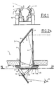
- FIG 1 there is shown schematically a vehicle 1, for example a vehicle of the military type, with which the combatants are brought to move.
- the internal enclosure conventionally constitutes protection against ballistic, nuclear, biological aggressions and chemicals.
- an episcope 3 On the upper wall 2 of the enclosure, we fixes an episcope 3 whose role is to allow a fighter 12 to observe his outside environment, following field E in a direction opposite to the gaze direction. This direction could be good heard that of the look.
- the lower part of an episcope known has been eliminated and replaced with a face retractable reflective.
- the episcope 3 is integrated in an opening 4 made in the wall 2 and comprises conventionally a cover 5 and a transparent mass 6 here equipped with two reflecting faces 6a and 6b.
- the episcope is fixed via the rim 7 of the cover 5, a seal 8 being interposed between this ledge and the wall 2.
- the episcope 3 therefore comprises a entry window 9 arranged substantially vertically at projecting outside and an exit window 10.
- the window 10 is tilted at an acute angle relative to a plane passing through the entrance window 9 to cooperate with a mirror 11 in order to cover the field of vision of the episcope on the one hand and to compensate for the variations of tilt of the mirror related to the size of the observer.
- the light rays coming from outside are therefore think twice before hitting the mirror 11.
- the mirror 11 is made retractable by rotation at using an articulated system comprising a base 13 integral with the rim 7 or the wall 2, for example by screwing or welding.
- the base 13 is provided with a slot 14 longitudinal and an axis 15, held in a position fixed, around which the support 16 of the mirror pivots.
- a connecting rod 17 is fixedly connected to the support 16 by a axis 18 distant from axis 15 and to an axis 19 sliding in the slot 14.
- the articulated system is therefore delimited by the base 13, the support 14 and the connecting rod 17 and gives the mirror 11 any angular position relative to the exit window 10.
- FIG. 2B there is shown an episcope 6 almost identical to that of FIG. 2A with the exception of the upper part projecting from the enclosure 2.
- the episcope 6 has only one reflective face 6c for transmitting rays bright in the direction of the observer's gaze. The light ray undergoes only one reflection before reaching the mirror 11.
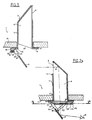
- the slot 14 is made at the base 13. It could be arranged without difficulty on the support 16 of the mirror, the connecting rod 17 being then fixed on the base. There is shown a slot 14 occupying practically the width of the base to allow the retraction of the mirror 11 either towards the base 13 as shown in Figure 3, either opposite to it in the extension of the base as shown in Figure 4.
- FIG. 3 there is shown the mirror 11 in its retracted position, that is, it was brought back against the exit window 10 by rotation, means being provided to maintain this mirror 7 in this position.
- the episcope 3 thus modified no longer constitutes embarrassment for the fighter when he wants to access his post or get out. Congestion, especially in height, is therefore reduced to a minimum.
- the combatant can observe the environment in front (fig. 2B) or behind him (fig.2A).
- the mirror 11 is folded against the base 13 towards the outlet window 10, the connecting rod 17 being applied against the base and the axis 19 being placed at the level of the free end of the slot 14 not visible on the drawing.
- the mirror 11 is folded down in the direction opposite to that of figure 2, the window of outlet 10 being completely clear.
- the axis 19 fixed to the connecting rod 17 is brought back in the vicinity of axis 15 fixed in the vicinity of the other end of the slot 14.
- Figure 5 illustrates another variant of realization of the retraction of the mirror 11 by rotation.
- This mirror is fixed to a support 20 extended by one end 21 semi-cylindrical fixed to the edge 7 of the cover 5 of the episcope 3.
- the end 21 is provided on its periphery a toothing 22 intended to cooperate with a ball 23 subjected to the action of a spring 24 engaged in a housing blind 25 practiced in a bead 26 integrated into the rim 7.
- the support 20 is rotatably mounted by relative to an axis 27 integral with the rim 7 or the wall 2.
- the ball 23 maintains the mirror 11 in the angular position desired by the user.
- the tooth upper determines the retracting position of the mirror and the lower tooth fixes the maximum spacing of the mirror 11 relative to the exit window 10 of the episcope 3.
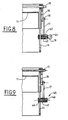
- Figures 6 and 7 illustrate the retraction of the mirror 11 by translation.
- the mirror 11 is integral a support 28 comprising an inclined bottom 29, on which the mirror is fixed, and two side walls 30, one of which only is shown in the figures.
- window 9 could be oriented as shown in Figure 2B.
- the walls 30 carry fingers 31 to slide relative to two guides 32 provided grooves 33 (only one guide is visible in the figures).
- the walls 30 and the guides 32 are arranged two to two on each side of the episcope, for example in the cover 5 thereof.
- Figure 6 shows the position lower of mirror 11 and figure 7 the position retraction to the exit window 10.
- Figures 8 and 9 illustrate sections AA according to the FIG. 2A with a device for indexing the mirror 11.
- Figure 8 shows a first embodiment according to which the connecting rod 17 is rigidly fixed on one side to the support 16 by axis 18 and connected at the other end to the base 13 by the axis 19 extended externally by a button 41.
- the axis 19 slides in a body 42 connected to the base 13, a spring 43 holding said axis in support constant in groove 14 to ensure indexing.
- FIG. 9 illustrates an indexing system 45 according to which constant support is obtained by a ball 46 submitted to the action of a spring 47, the assembly being integrated in a cover 48.
Description
L'invention concerne un dispositif d'observation à travers la paroi d'une enceinte de protection à l'aide d'un épiscope, c'est-à-dire d'un instrument optique permettant d'observer à travers une paroi derrière laquelle l'observateur est protégé.The invention relates to an observation device with through the wall of a protective enclosure using a episcope, that is to say an optical instrument allowing to observe through a wall behind which the observer is protected.
On a déjà proposé des dispositifs de levage du porte-objet pour des épiscopes en prévoyant deux leviers doubles. Ces dispositifs sont décrits dans les documents FR-A-2 056 673 et FR-A-2 234 579. Cependant, dans ces documents, aucun moyen n'est prévu pour réduire la hauteur de l'épiscope.Devices for lifting the object holder have already been proposed for episcopes by providing two double levers. These devices are described in documents FR-A-2 056 673 and FR-A-2 234 579. However, in these documents, no means are provided to reduce the height of the bishop.
On a également proposé des systèmes d'observation dans lesquels un miroir est monté pivotant par rapport à son support. Ainsi, le brevet FR-A-407 463 décrit un dispositif d'observation équipé de deux miroirs, le miroir inférieur étant articulé pour permettre le réglage de son orientation par rapport à l'oeil d'un observateur. Ce miroir demeure toujours dans la zone d'évolution de l'observateur.Observation systems have also been proposed in which a mirror is pivotally mounted relative to its support. Thus, patent FR-A-407,463 describes a device observation mirror equipped with two mirrors, the lower mirror being articulated to allow adjustment of its orientation compared to the eye of an observer. This mirror remains always in the observer's evolution zone.
Le brevet EP-A-0 550 869 décrit un épiscope constitué des deux miroirs fixés chacun à deux supports respectifs. L'un des deux miroirs est pivotant par rapport à son support afin de permettre d'atteindre le second pour le nettoyer.Patent EP-A-0 550 869 describes an episcope consisting of two mirrors each attached to two respective supports. Mon of the two mirrors is pivotable relative to its support so allow to reach the second to clean it.
Dans un véhicule militaire destiné par exemple au transport de troupes, il est nécessaire que chaque combattant puisse observer le paysage extérieur. On pourrait pour cela prévoir un épiscope au travers duquel cette observation serait possible. Mais dans ce cas, l'épiscope doit faire saillie dans l'habitacle, ce qui constitue un obstacle susceptible d'entraver les mouvements des combattants surtout lors des opérations d'évacuation.In a military vehicle intended for example for troop transport, it is necessary that each fighter can observe the outside landscape. We could for that provide an episcope through which this observation would be possible. But in this case, the episcope must do protruding into the passenger compartment, which constitutes an obstacle likely to hinder the movements of combatants especially during evacuation operations.
Le but de la présente invention est de fournir un dispositif d'observation implanté dans la paroi d'un véhicule et ne faisant saillie que faiblement à l'intérieur de ce véhicule.The object of the present invention is to provide a observation device installed in the wall of a vehicle and protruding only slightly inside this vehicle.
Pour atteindre ce but, l'invention propose un dispositif d'observation à travers la paroi d'une enceinte de protection, telle un véhicule militaire, à l'aide d'un épiscope fixé au niveau de ladite paroi muni d'une fenêtre externe d'entrée de rayons lumineux et d'une fenêtre interne de sortie, comprenant un miroir coopérant avec la fenêtre de sortie pour assurer la transmission des rayons lumineux dans une direction opposée à celle de la direction d'observation, caractérisé en ce que le miroir est escamotable à l'aide d'un système articulé reliant ce miroir à l'épiscope pour lui permettre d'occuper une position escamotée dans laquelle il est appliqué contre la fenêtre de sortie et une position déployée dans laquelle il permet l'observation.To achieve this goal, the invention provides a device observation through the wall of an enclosure of protection, such as a military vehicle, using a episcope fixed at the level of said wall provided with a window external light beam entry and internal window outlet, comprising a mirror cooperating with the window output to ensure the transmission of light rays in a direction opposite to that of the direction of observation, characterized in that the mirror is retractable using a articulated system connecting this mirror to the episcope for him allow to occupy a retracted position in which it is applied against the exit window and a position deployed in which it allows observation.
Selon une caractéristique, le bloc transparent comporte une ou deux faces de réflexion.According to one characteristic, the transparent block comprises one or two reflection faces.
Selon un mode de réalisation, le miroir est escamotable par rotation.According to one embodiment, the mirror is retractable by rotation.
Selon une caractéristique, le système articulé est constitué d'une embase munie d'une rainure, d'un support articulé à une extrémité de l'embase et d'un bras relié à une extrémité au support et à l'autre à un axe coulissant dans la rainure.According to one characteristic, the articulated system is consisting of a base provided with a groove, a support articulated at one end of the base and an arm connected to a end to the support and at the other to a sliding axis in the groove.
Selon une autre caractéristique, la fenêtre de sortie de l'épiscope est inclinée d'un angle aigü par rapport à un plan passant par la fenêtre de d'entrée.According to another characteristic, the exit window of the episcope is tilted at an acute angle to a plane passing through the entry window.
Selon encore une autre caractéristique, le miroir est rabattable contre la fenêtre de sortie ou à l'opposé de celle-ci.According to yet another characteristic, the mirror is folds against the exit window or opposite it.
Selon encore une autre caractéristique, le système articulé est constitué d'un support dont l'extrémité est articulée par rapport à l'épiscope et présente une surface semi-cylindrique coopérant avec un moyen de maintien du miroir dans une position angulaire déterminée.According to yet another characteristic, the system articulated consists of a support whose end is articulated with respect to the episcope and has a surface semi-cylindrical cooperating with a means for maintaining the mirror in a determined angular position.
Selon un autre mode de réalisation, le miroir est escamotable par translation à l'aide d'un système de guidage reliant ce miroir à l'épiscope pour lui permettre d'occuper une position escamotée dans laquelle il est appliqué contre la fenêtre de sortie et une position déployée dans laquelle il permet l'observation.According to another embodiment, the mirror is retractable by translation using a guidance system connecting this mirror to the episcope to allow it to occupy a retracted position in which it is applied against the exit window and a deployed position in which it allows observation.
Avantageusement, le dispositif comprend des moyens pour maintenir le miroir dans une position angulaire fixe par rapport à l'épiscope. Advantageously, the device comprises means for hold the mirror in a fixed angular position by compared to the episcope.
Le miroir est du type plan ou concave.The mirror is of the flat or concave type.
Un tout premier avantage de l'invention réside dans le fait que l'encombrement est réduit pour l'observateur, ce qui facilite l'accès à son poste d'observation.A very first advantage of the invention lies in the the space requirement is reduced for the observer, which facilitates access to its observation post.
Un autre avantage de l'invention réside dans l'ajustement variable de la position du miroir en fonction de la taille de l'observateur.Another advantage of the invention lies in the adjustment variable of the position of the mirror according to the size of the observer.
D'autres caractéristiques, détails et avantages de l'invention apparaítront plus clairement à la lecture du complément de description qui va suivre de modes de réalisation donnés à titre d'exemple en relation avec des dessins sur lesquels :
- la figure 1 représente une vue générale de l'implantation du dispositif selon l'invention dans un véhicule,
- les figures 2A et 2B représente des vues en coupe schématique montrant l'implantation du dispositif d'observation en position d'utilisation,
- les figures 3 et 4 représentent des vues schématiques montrant le miroir en position escamotée,
- la figure 5 montre une variante de la structure des moyens d'articulation,
- les figures 6 et 7 montrent des moyens d'escamotage en translation,
- et les figures 8 et 9 représentent des coupes AA de la figure 2 montrant notamment les moyens de blocage de la position angulaire du miroir.
- FIG. 1 represents a general view of the installation of the device according to the invention in a vehicle,
- FIGS. 2A and 2B represent diagrammatic section views showing the installation of the observation device in the position of use,
- FIGS. 3 and 4 represent schematic views showing the mirror in the retracted position,
- FIG. 5 shows a variant of the structure of the articulation means,
- FIGS. 6 and 7 show means of retraction in translation,
- and Figures 8 and 9 show sections AA of Figure 2 showing in particular the means for blocking the angular position of the mirror.
Sur la figure 1, on a représenté schématiquement un
véhicule 1, par exemple un véhicule du type militaire, avec
lequel les combattants sont amenés à se déplacer.
L'enceinte interne constitue classiquement une protection
contre les agressions balistiques, nucléaires, biologiques
et chimiques. Sur la paroi supérieure 2 de l'enceinte, on
fixe un épiscope 3 dont le rôle est de permettre à un
combattant 12 d'observer son environnement extérieur,
suivant le champ E dans une direction opposée à la
direction du regard. Cette direction pourrait être bien
entendu celle du regard.In Figure 1, there is shown schematically a
Selon l'invention, la partie basse d'un épiscope connu a été éliminée et remplacée par une face réfléchissante escamotable.According to the invention, the lower part of an episcope known has been eliminated and replaced with a face retractable reflective.
L'épiscope 3 suivant la figure 2A est intégré dans
une ouverture 4 pratiquée dans la paroi 2 et comprend
classiquement un capot 5 et une masse transparente 6
équipée ici de deux faces réfléchissantes 6a et 6b.
L'épiscope est fixé par l'intermédiaire du rebord 7 du
capot 5, un joint d'étanchéité 8 étant interposé entre ce
rebord et la paroi 2. L'épiscope 3 comprend donc une
fenêtre d'entrée 9 disposée sensiblement verticalement en
faisant saillie à l'extérieur et une fenêtre de sortie 10.
La fenêtre 10 est inclinée d'un angle aigü par rapport à un
plan passant par la fenêtre d'entrée 9 pour coopérer avec
un miroir 11 afin de couvrir le champ de vision de
l'épiscope d'une part et de compenser les variations
d'inclinaison du miroir liées à la taille de l'observateur.
Les rayons lumineux venant de l'extérieur sont donc
réfléchis deux fois avant de frapper le miroir 11.The
Le miroir 11 est rendu escamotable par rotation à
l'aide d'un système articulé comprenant une embase 13
solidaire du rebord 7 ou de la paroi 2, par exemple par
vissage ou soudage. L'embase 13 est munie d'une fente 14
longitudinale et d'un axe 15, maintenu dans une position
fixe, autour duquel pivote le support 16 du miroir. Une
bielle 17 est reliée de manière fixe au support 16 par un
axe 18 éloigné de l'axe 15 et à un axe 19 coulissant dans
la fente 14. Le système articulé est donc délimité par
l'embase 13, le support 14 et la bielle 17 et confère au
miroir 11 une position angulaire quelconque par rapport à
la fenêtre de sortie 10.The
Sur la figure 2B, on a représenté un épiscope 6
quasiment identique à celui de la figure 2A à l'exception
de la partie haute en saillie par rapport à l'enceinte 2.
Dans cette réalisation, l'épiscope 6 ne comporte qu'une
face 6c réfléchissante permettant de transmettre les rayons
lumineux dans la direction du regard de l'observateur. Le
rayon lumineux ne subit qu'une reflexion avant d'atteindre
le miroir 11.In Figure 2B, there is shown an
Comme décrit précédemment, la fente 14 est pratiquée
au niveau de l'embase 13. Elle pourrait être disposée sans
difficulté sur le support 16 du miroir, la bielle 17 étant
alors fixée sur l'embase. On a représenté une fente 14
occupant pratiquement la largeur de l'embase pour permettre
l'escamotage du miroir 11 soit vers l'embase 13 comme
montré sur la figure 3, soit à l'opposé de celle-ci dans le
prolongement de l'embase comme représenté sur la figure 4.As described above, the slot 14 is made
at the
Sur la figure 3, on a représenté le miroir 11 dans sa
position escamotée, c'est-à-dire qu'il a été ramené contre
la fenêtre de sortie 10 par rotation, des moyens étant
prévus pour maintenir ce miroir 7 dans cette position. De
cette manière, l'épiscope 3 ainsi modifié ne constitue plus
une gêne pour le combattant lorsque celui-ci veut accéder à
son poste ou en sortir. L'encombrement, notamment en
hauteur, est donc réduit au minimum. De plus, suivant
l'orientation de la fenêtre d'entrée 9, le combattant peut
observer l'environnement qui est devant (fig. 2B) ou
derrière lui (fig.2A). Le miroir 11 est rabattu contre
l'embase 13 vers la fenêtre de sortie 10, la bielle 17
étant appliquée contre l'embase et l'axe 19 étant placé au
niveau de l'extrémité libre de la fente 14 non visible sur
le dessin. Sur la figure 4, le miroir 11 est rabattu dans
la direction opposée à celle de la figure 2, la fenêtre de
sortie 10 étant complètement dégagée. Dans cette position,
l'axe 19 fixé à la bielle 17 est ramené au voisinage de
l'axe 15 fixé au voisinage de l'autre extrémité de la fente
14. On peut considérer cette configuration comme un
escamotage d'urgence utilisé par l'observateur 12 en cas de
sortie précipitée.In Figure 3, there is shown the
La figure 5 illustre une autre variante de
réalisation de l'escamotage du miroir 11 par rotation. Ce
miroir est fixé à un support 20 prolongé par une extrémité
21 semi-cylindrique fixée au rebord 7 du capot 5 de
l'épiscope 3. L'extrémité 21 est munie sur sa périphérie
d'une denture 22 destinée à coopérer avec une bille 23
soumise à l'action d'un ressort 24 engagé dans un logement
borgne 25 pratiqué dans un bourrelet 26 intégré au rebord
7. Bien entendu, le support 20 est monté rotatif par
rapport à un axe 27 solidaire du rebord 7 ou de la paroi 2.
Ainsi, la bille 23 assure le maintien du miroir 11 dans la
position angulaire souhaitée par l'utilisateur. La dent
supérieure détermine la position d'escamotage du miroir et
la dent inférieure fixe l'écartement maximum du miroir 11
par rapport à la fenêtre de sortie 10 de l'épiscope 3.Figure 5 illustrates another variant of
realization of the retraction of the
Les figures 6 et 7 illustrent l'escamotage du miroir
11 par translation. A cette fin, le miroir 11 est solidaire
d'un support 28 comprenant un fond incliné 29, sur lequel
le miroir est fixé, et deux parois latérales 30 dont une
seule est représentée sur les figures. Dans cette
réalisation, deux réflexions se produisent dans le bloc
transparent 6. Mais la fenêtre 9 pourrait être orientée
comme montré sur la figure 2B. Les parois 30 portent des
doigts 31 pour coulisser par rapport à deux guides 32 munis
de rainures 33 (un seul guide est visible sur les figures).
Bien entendu, les parois 30 et les guides 32 sont disposés
deux à deux de chaque côté de l'épiscope, par exemple dans
le capot 5 de celui-ci. La figure 6 montre la position la
plus basse du miroir 11 et la figure 7 la position
d'escamotage vers la fenêtre de sortie 10.Figures 6 and 7 illustrate the retraction of the
Les figures 8 et 9 illustrent des coupes AA selon la
figure 2A avec un dispositif d'indexation du miroir 11.Figures 8 and 9 illustrate sections AA according to the
FIG. 2A with a device for indexing the
La figure 8 montre une première réalisation selon
laquelle la bielle 17 est fixée d'un côté rigidement au
support 16 par l'axe 18 et reliée à l'autre extrémité à
l'embase 13 par l'axe 19 prolongé extérieurement par un
bouton 41. L'axe 19 coulisse dans un corps 42 relié à
l'embase 13, un ressort 43 maintenant ledit axe en appui
constant dans la rainure 14 pour assurer l'indexation.Figure 8 shows a first embodiment according to
which the connecting
La figure 9 illustre un système d'indexation 45 selon
lequel l'appui constant est obtenu par une bille 46 soumise
à l'action d'un ressort 47, l'ensemble étant intégré dans
un capot 48.FIG. 9 illustrates an
Claims (10)
- An observation device through the wall of a protective enclosure, such as a military vehicle, using an episcope (3) fastened to said wall (2) and provided with an external inlet window (9) for light rays and an internal outlet window (10), comprising a mirror (11) cooperating with the outlet window (10) to ensure the transmission of the light rays in a direction opposed to that of the observation direction, wherein the mirror (11) may be retracted using an articulated system (13, 16, 17) connecting this mirror (11) to the episcope (3) to enable it to occupy a retracted position in which it is applied against the outlet window (10) and a deployed position in which it makes observation possible.
- An observation device according to Claim 1, wherein the transparent block (6) incorporates one (9c) or two (9a, 9b) reflective surfaces.
- An observation device according to Claim 2, wherein the mirror (11) is retracted by rotation.
- An observation device according to anyone of the preccedings Claims, wherein the articulated system is constituted by a base (13) provided with a groove (14), a support (16) articulated at one end of the base and an arm (17) connected at one end to the support and at the other to a spindle (19) sliding in the groove.
- An observation device according to Claim 4, wherein the outlet window (10) of the episcope is inclined at a sharp angle with respect to a plane passing through the inlet window (9).
- An observation device according to Claim 4, wherein the mirror (11) can be pushed back against the outlet window or on the opposite side to it.
- An observation device according to Claim 1, wherein the articulated system is constituted by a support (20) whose end is articulated with respect to the episcope and which has a semi-cylindrical surface cooperating with means to retain the mirror in a predetermined angular position.
- An observation device according to Claim 1, wherein the mirror (11) is retracted by translation using a guidance system (30, 31) linking this mirror (11) to the episcope (3) to allow it to occupy a retracted position in which it is applied against the outlet window (10) and a deployed position in which observation is possible.
- An observation device according to any one of the above Claims, wherein it comprises means to retain the mirror (7) in an angular position that is fixed with respect to the episcope (3).
- An observation device according t one of the above Claims, wherein the mirror (7) is of the plane or concave type.
Applications Claiming Priority (2)
| Application Number | Priority Date | Filing Date | Title |
|---|---|---|---|
| FR9712468A FR2769378B1 (en) | 1997-10-07 | 1997-10-07 | DEVICE FOR OBSERVING THROUGH THE WALL OF A PROTECTIVE ENCLOSURE USING AN EPISCOPE |
| FR9712468 | 1997-10-07 |
Publications (2)
| Publication Number | Publication Date |
|---|---|
| EP0908752A1 EP0908752A1 (en) | 1999-04-14 |
| EP0908752B1 true EP0908752B1 (en) | 2004-07-07 |
Family
ID=9511900
Family Applications (1)
| Application Number | Title | Priority Date | Filing Date |
|---|---|---|---|
| EP19980402361 Expired - Lifetime EP0908752B1 (en) | 1997-10-07 | 1998-09-25 | Device for observation through the wall of a protective enclosure by means of an episcope |
Country Status (3)
| Country | Link |
|---|---|
| EP (1) | EP0908752B1 (en) |
| DE (1) | DE69824931T2 (en) |
| FR (1) | FR2769378B1 (en) |
Families Citing this family (5)
| Publication number | Priority date | Publication date | Assignee | Title |
|---|---|---|---|---|
| FR2882445B1 (en) | 2005-02-24 | 2007-06-01 | Giat Ind Sa | COMBINABLE EPISCOPE OBSERVATION DEVICE |
| DE102008021486B4 (en) * | 2008-04-29 | 2010-06-24 | Krauss-Maffei Wegmann Gmbh & Co. Kg | Folding angle mirror for combat vehicles |
| GB2519767B (en) * | 2013-10-29 | 2018-05-09 | Kent Periscopes Ltd | Periscope |
| FR3015697A1 (en) * | 2013-12-19 | 2015-06-26 | France Etat | EPISCOPE OF CREVEL |
| DE102015122411A1 (en) | 2015-12-21 | 2017-06-22 | Krauss-Maffei Wegmann Gmbh & Co. Kg | Folding angle mirror and viewing device |
Family Cites Families (12)
| Publication number | Priority date | Publication date | Assignee | Title |
|---|---|---|---|---|
| FR407463A (en) * | 1909-09-30 | 1910-03-01 | Marie Alexandre Leon Lefebure | Apparatus reproducing under the eyes of an observer the image of objects placed behind him |
| US1466567A (en) * | 1920-09-03 | 1923-08-28 | Raymond W Smith | Reflector for autos |
| DE661055C (en) * | 1935-02-04 | 1938-06-09 | Rudolf Gundlach | Periscope for armored caterpillars etc. |
| US2570357A (en) * | 1950-03-08 | 1951-10-09 | Tolly C Martin | Periscope for motor vehicles |
| FR1170518A (en) * | 1957-04-01 | 1959-01-15 | Device for fixing an armored vehicle periscope | |
| US3165573A (en) * | 1958-09-29 | 1965-01-12 | Charles W Moultrie | Vision device for vehicles |
| US3229576A (en) * | 1962-11-21 | 1966-01-18 | Donald W Rees | Hyperbolic ellipsoidal real time display panoramic viewing installation for vehicles |
| US3857632A (en) * | 1971-10-11 | 1974-12-31 | Ichikoh Industries Ltd | Rear vision mirror apparatus having a filter for automobile |
| GB2089519B (en) * | 1980-12-17 | 1984-06-13 | Philips Electronic Associated | Stowable sighting instrument |
| FR2496905A1 (en) * | 1980-12-24 | 1982-06-25 | France Etat | EPISCOPE WITH MULTIMODES REFLECTIONS |
| DE4015346A1 (en) * | 1990-05-12 | 1991-11-14 | Wegmann & Co | FIGHTING VEHICLE, IN PARTICULAR FIGHTING TANK, WITH A HAT ARRANGED IN THE ARMORED HOUSING OF THE VEHICLE |
| DE4200261A1 (en) * | 1992-01-08 | 1993-07-15 | Wegmann & Co Gmbh | ANGLE MIRROR ON THE EXIT HAT OF A COMBAT VEHICLE |
-
1997
- 1997-10-07 FR FR9712468A patent/FR2769378B1/en not_active Expired - Fee Related
-
1998
- 1998-09-25 DE DE69824931T patent/DE69824931T2/en not_active Expired - Lifetime
- 1998-09-25 EP EP19980402361 patent/EP0908752B1/en not_active Expired - Lifetime
Also Published As
| Publication number | Publication date |
|---|---|
| FR2769378B1 (en) | 2000-12-29 |
| DE69824931T2 (en) | 2005-07-21 |
| FR2769378A1 (en) | 1999-04-09 |
| EP0908752A1 (en) | 1999-04-14 |
| DE69824931D1 (en) | 2004-08-12 |
Similar Documents
| Publication | Publication Date | Title |
|---|---|---|
| EP1948465B1 (en) | Retractable display device for a motor vehicle and a vehicle provided therewith | |
| EP3404176B1 (en) | Device for unlocking a door latch | |
| EP1108580B1 (en) | Tailgate for motor vehicle | |
| EP0136951B1 (en) | Mixed apparatus for projecting and retro-projecting slides | |
| EP0908752B1 (en) | Device for observation through the wall of a protective enclosure by means of an episcope | |
| EP0192309B1 (en) | Day-night observation apparatus | |
| FR2942489A1 (en) | LUMINOUS CABINET WITH SPRING COMPASS OPENING | |
| EP3016821B1 (en) | Luggage cover system for motor vehicle | |
| EP0193236B1 (en) | Day-night vision device with a wide viewing angle | |
| EP0192549B1 (en) | Antivibratory device for a vehicle rear-view mirror | |
| FR3107679A1 (en) | Connection system for mounting a storage bin on a support attached to a body of a motor vehicle. | |
| EP3755966B1 (en) | Protective device for an orientable viewfinder | |
| FR2888274A1 (en) | Opening frame e.g. cover of rear boot, supporting mechanism for motor vehicle, has articulated connecting rods to moved between open and closing positions, where one rod directly connects structure element and cover | |
| FR2891505A1 (en) | Headrest for motor vehicle, has connecting rod provided to connect fixed and mobile parts, and slots comprising inclined portion in which pivots housed when mobile part is in normal position, and allowing pivots to offset | |
| FR2793754A1 (en) | Hatchback for car has inner and outer panels, and articulation system restraining interference between bumper and outer panel when hatchback is opened | |
| EP0741982B1 (en) | Eye make-up device | |
| EP0380891A1 (en) | Shield for the rear part of a vehicle passenger compartment | |
| FR3070652A1 (en) | AUTOMOTIVE VEHICLE LUGGAGE COMPARTMENT REPAIR SYSTEM | |
| EP3524476B1 (en) | Partitioning device for a vehicle | |
| EP0057154A1 (en) | Reversible rear view mirror | |
| EP3670271B1 (en) | Deployment device of a camera for a motor-propelled vehicle | |
| FR3064660A1 (en) | LOCKING DEVICE FOR STORAGE COMPARTMENT COVER, ASSOCIATED STORAGE COMPARTMENT AND VEHICLE THEREFOR | |
| EP1559609A1 (en) | Display device for motor vehicle | |
| EP1736362B1 (en) | Collapsible mechanism for partitioning the load compartment of a motor vehicle and corresponding motor vehicle | |
| FR2760611A1 (en) | STORAGE DEVICE FORMED IN A SOFA OR ARMCHAIR |
Legal Events
| Date | Code | Title | Description |
|---|---|---|---|
| PUAI | Public reference made under article 153(3) epc to a published international application that has entered the european phase |
Free format text: ORIGINAL CODE: 0009012 |
|
| AK | Designated contracting states |
Kind code of ref document: A1 Designated state(s): DE FR GB |
|
| AX | Request for extension of the european patent |
Free format text: AL;LT;LV;MK;RO;SI |
|
| 17P | Request for examination filed |
Effective date: 19990510 |
|
| AKX | Designation fees paid |
Free format text: DE FR GB |
|
| 17Q | First examination report despatched |
Effective date: 20030113 |
|
| GRAP | Despatch of communication of intention to grant a patent |
Free format text: ORIGINAL CODE: EPIDOSNIGR1 |
|
| GRAS | Grant fee paid |
Free format text: ORIGINAL CODE: EPIDOSNIGR3 |
|
| GRAA | (expected) grant |
Free format text: ORIGINAL CODE: 0009210 |
|
| AK | Designated contracting states |
Kind code of ref document: B1 Designated state(s): DE FR GB |
|
| REG | Reference to a national code |
Ref country code: GB Ref legal event code: FG4D Free format text: NOT ENGLISH |
|
| GBT | Gb: translation of ep patent filed (gb section 77(6)(a)/1977) |
Effective date: 20040707 |
|
| REF | Corresponds to: |
Ref document number: 69824931 Country of ref document: DE Date of ref document: 20040812 Kind code of ref document: P |
|
| PLBE | No opposition filed within time limit |
Free format text: ORIGINAL CODE: 0009261 |
|
| STAA | Information on the status of an ep patent application or granted ep patent |
Free format text: STATUS: NO OPPOSITION FILED WITHIN TIME LIMIT |
|
| 26N | No opposition filed |
Effective date: 20050408 |
|
| REG | Reference to a national code |
Ref country code: FR Ref legal event code: TP |
|
| REG | Reference to a national code |
Ref country code: DE Ref legal event code: R082 Ref document number: 69824931 Country of ref document: DE Representative=s name: HUBER & SCHUESSLER, DE |
|
| REG | Reference to a national code |
Ref country code: GB Ref legal event code: 732E Free format text: REGISTERED BETWEEN 20150220 AND 20150225 |
|
| REG | Reference to a national code |
Ref country code: DE Ref legal event code: R082 Ref document number: 69824931 Country of ref document: DE Representative=s name: HUBER & SCHUESSLER, DE Effective date: 20150215 Ref country code: DE Ref legal event code: R081 Ref document number: 69824931 Country of ref document: DE Owner name: OPTSYS, FR Free format text: FORMER OWNER: GIAT INDUSTRIES, VERSAILLES, FR Effective date: 20150215 |
|
| REG | Reference to a national code |
Ref country code: FR Ref legal event code: PLFP Year of fee payment: 19 |
|
| REG | Reference to a national code |
Ref country code: FR Ref legal event code: PLFP Year of fee payment: 20 |
|
| PGFP | Annual fee paid to national office [announced via postgrant information from national office to epo] |
Ref country code: DE Payment date: 20170821 Year of fee payment: 20 Ref country code: FR Payment date: 20170822 Year of fee payment: 20 Ref country code: GB Payment date: 20170821 Year of fee payment: 20 |
|
| REG | Reference to a national code |
Ref country code: DE Ref legal event code: R071 Ref document number: 69824931 Country of ref document: DE |
|
| REG | Reference to a national code |
Ref country code: GB Ref legal event code: PE20 Expiry date: 20180924 |
|
| PG25 | Lapsed in a contracting state [announced via postgrant information from national office to epo] |
Ref country code: GB Free format text: LAPSE BECAUSE OF EXPIRATION OF PROTECTION Effective date: 20180924 |